Daikin DPS Installation And Maintenance Manual
Microtech iii unit controller for rebel commercial packaged rooftop systems
Hide thumbs
Also See for DPS:
- Installation and maintenance manual (82 pages) ,
- Installation manual (6 pages) ,
- Installation and maintenance manual (20 pages)
Table of Contents
Advertisement
Quick Links
Download this manual
See also:
Installation Manual
Advertisement
Table of Contents
Troubleshooting

Related Manuals for Daikin DPS


Summary of Contents for Daikin DPS
- Page 1 Installation and Maintenance Manual OM 1141-3 Group: Applied Air Systems Part Number: OM 1141 Date: October 2014 MicroTech III Unit Controller for ® Rebel Commercial Packaged Rooftop Systems ® Model DPS...
-
Page 2: Table Of Contents
Introduction . . . . . . . . . . . . . . . . . . . . . . . . . . . . . . . . . . . . . . . . . . . . . 4 Service Menus . - Page 3 Operator’s Guide . . . . . . . . . . . . . . . . . . . . . . . . . . . . . . . . . . . . . . . 82 Heat Pump .
-
Page 4: Introduction
IM 919 Figure 1: Projected Error Timeline MicroTech III Remote Unit IM 1005 Interface DPS 03 – 12 IM 1125 NOTICE This equipment generates, uses, and can radiate radio frequency energy and, if not installed and used in accordance with this instruction manual, may cause interference to radio communications . -
Page 5: Introduction
ntroductIon ntroductIon Getting Started CAUTION Extreme temperature hazard . Can cause damage to This manual contains information designed to assist the field system components . technician with unit setup . The technician will need to be familiar with the following topics at a minimum to successfully The MicroTech III controller is designed to operate in ambient set up unit operation . -
Page 6: Ifb Board
The IFB board is used to translate between the MicroTech III interconnected forming the ACS1 communication loop . On controller Modbus and the Daikin inverter compressor/outdoor 208/230V units the A4P board controls both INV and OF1 . On fan boards’ proprietary protocol . -
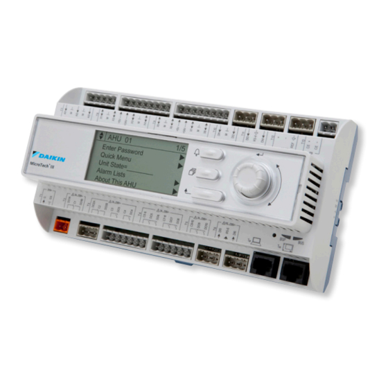
Page 7: Using The Keypad/Display
sIng the eypad Isplay sIng the eypad Isplay The keypad/display consists of a 5-line by 22 character display, Passwords three keys and a “push and roll” navigation wheel . There is an Alarm Button, Menu (Home) Button, and a Back Button . The Various menu functions are accessible or inaccessible, wheel is used to navigate between lines on a screen (page) depending on the access level of the user, and the password... -
Page 8: Navigation Mode
sIng the eypad Isplay Navigation Mode Edit Mode In the Navigation Mode, when a line on a page contains no The Editing Mode is entered by pressing the navigation wheel editable fields all but the value field of that line is highlighted while the cursor is pointing to a line containing an editable field. -
Page 9: Manual Control
sIng the eypad Isplay Manual Control A user may manually control outputs to check operation of All alarms except those listed below are overridden during components when Manual Control is set to ManCtrl . When Manual Control . Manual Control is set to ManCtrl, the unit is disabled and During manual control, the unit will respond in the normal the unit is shut down in the normal manner if it is operating . -
Page 10: Keypad/Display Menu Structure
eypad Isplay tructure eypad Isplay tructure The following is a description of the MicroTech III menu structure . These menus and items can all be displayed with the keypad/ display. Menu items displayed will change based on the selected unit configuration. Figure 7: Main Menu –... - Page 11 eypad Isplay tructure See page 34 — 58 See page 60 — 61 See page 62 — 67 See page 70 — See page 62 Commission Unit Manual Control Service Menus Unit Maintenance ► ► Trending Unit Set-Up Manual Control= Normal CFan Outpt 1= Off Timer Settings Operating Hours...
- Page 12 eypad Isplay tructure Figure 8: View/Set Unit – Keypad/Display Menu Structure See page 25 — 33 View/Set Unit ► Unit Status/Settings ► Occupancy ► Temperatures ► Flow Status ► SAF Spd Control ► RF/EF Control ► Cooling ► Economizer ► Min OA Damper ►...
- Page 13 eypad Isplay tructure See page 31 See page 32 See page 30 See page 30 See page 30 See page 30 Dehumidification Date/Time/Schedules Cooling Economizer Min OA Damper Heating Dehum Status= ________ Time= hh:mm:ss Occ Clg Spt= 72 .0°F OAD/Econo Pos= XXX% Min OA Pos= XXX% Occ Htg Spt= 68 .0°F Rel Humidity= XXX%...
- Page 14 Clg Stage Time= 5min 55°F (RTU/SCU) 0°F (MPS) INV Cmp Spd= XXX .X% Comp 1= _____________ Chgover Temp= 55 .0°F 25°F (DPS) INV Spd Cmd= XXX .X% Comp 3= _____________ Clg DB= 2 .0°F Comp 5= _____________ Econo Period= Comp 3=_____________ Htg Lo OAT Lk= ►...
- Page 15 Max Clg Chg= 5 .0°F 0°F (MPS) RF @ SF Max= 95% Exh Stg 2 On= 55% Occ Htg DB= 2 .0°F 25°F (DPS or RTU w/ Sup Fan Min= 30% Exh Stg 2 Off= 40% Htg Period= 60s VFD Cmps)
- Page 16 eypad Isplay tructure Figure 9 continued: Commission Unit – Keypad/Display Menu Structure See page 34 — 58 Commission Unit ► Unit Set-Up ► Timer Settings ► SAF Set-Up ► See page 51 — See page 53 — 54 See page 49 — RF/EF Set-Up ►...
- Page 17 ER Whl Gain= 1 .0 Rht Min Pos= 10% (RPS) ER Whl PAT= 30s 15% (MPS) ER Max Chg= 10% 5% (DPS, DPH) LoERLATCmpLk= 45 .0°F RH Dec Rate= 1 RHOutMaxV= 10 www .DaikinApplied .com OM 1141-3 • MICROTECH UNIT CONTROLLER...
- Page 18 eypad Isplay tructure Figure 10: Service Menu – Keypad/Display Menu Structure See page 62 — 67 Service Menus ► Timer Settings ► Operating Hours ► Save/Restore Settings ► Active Alarms ► Alarm Log ► Alarm Configuration ► Analog Input Status ►...
- Page 19 eypad Isplay tructure See page 63 See page 59 Alarm Log Alarm Configuration ► Log Count: xx Clr Log= No ALARM LIMITS page 21 ► 3, 4 See connection on +/-Alarm 1: Alarm Type Hi Disch Temp= 170°F ► +/-Alarm 2: Alarm Type Lo Disch Temp= 40°F ●...
- Page 20 eypad Isplay tructure Figure 10 continued: Service Menu – Keypad/Display Menu Structure See page 62 — 67 Service Menus ► Timer Settings ► Operating Hours ► Save/Restore Settings ► Active Alarms ► Alarm Log ► Alarm Configuration ► Analog Input Status ►...
- Page 21 eypad Isplay tructure See page 63 See page 63 See page 63 Alarm Lists Active Alarms Alarm Log Alarm Details ► ► Active Alarms Alm Count: xx Clr Alms= No Log Count: xx Clr Log= No +/-Alarm 1: Alarm Type ►...
- Page 22 eypad Isplay tructure Figure 11: BMS Communications – Keypad/Display Menu Structure See page 68 BMS Communications ► LON Set-Up ► BACnet MSTP Set-Up ► BACnet IP Set-Up ► D-Net Set-Up ► Network Unit Set-Up IM 918 IM 917 IM 916 LON Set-Up BACnet MSTP Set-Up BACnet IP Set-Up...
-
Page 23: Quick Menu
uIcK uIcK Items in the Quick Menu (see Table 2) contain basic unit operating status and control set point parameters . The items shown in the Quick Menu are Read Only if a valid password has not been entered . The following are brief descriptions of the Quick Menu items . No password is required to view the Quick Menu . - Page 24 uIcK Unit State is a status only item which indicates the state of DAT Htg Spt is a status only item which indicates the operation in which the unit is currently operating . The unit can temperature that the DAT should be maintained at when in the be in any of the operating states shown .
-
Page 25: View/Set Menu
Unit Status Settings The “Unit Status Settings” menu provides a summary of basic unit status and control items . This menu summarizes the current operating state of the unit, giving the operating state the unit is in, along with the current capacity level of that operating state . Table 3: Unit Status Settings For more detail Item Display Name... - Page 26 Unit State is a status only item which indicates the state of Supl Htg Cap (Heat Pump only) is a status only item which operation in which the unit is currently operating . The unit can indicates the percentage of the unit maximum supplemental heating be in any of the operating states shown .
-
Page 27: Occupancy Menu
Occupancy Menu Menus in the Occupancy menu contain status and control items that relate to unit occupied/unoccupied operation . Table 4: Occupancy Menu For more detail Item Display Name Default Setting Range Password Level See page 94 Occupancy= — Unocc Tnt Ovrd Unocc See page 95... -
Page 28: Temperature Menu
Temperature Menu Menus in the Temperatures menu contain unit temperature status information . Table 5: Temperature Menu Item Display Name Default Setting Range Password Level Control Temp= — -50 .0–200 .0°F Disch Air= — -50 .0–250 .0°F Return Air= — -20 .0–200 .0°F Space Temp= —... -
Page 29: Flow Status Menu
Flow Status Menu SAF Spd Control Menu Table 6: Flow Status Menu Table 8: Supply Fan Speed Menu Item Display Default Password Item Display Default Password Range Range Name Setting Level Name Setting Level No Flow SAF Speed= — 0–100% Airflow= —... -
Page 30: Cooling Menu
Cooling Menu Min OA Damper Menu Table 9: Cooling Menu Table 11: Min OA Damper Menu Item Display Default Password Item Display Default Password Range Range Name Setting Level Name Setting Level Occ Clg Spt= 72 .0°F 0 .0-100 .0°F Min OA Pos= —... -
Page 31: Heating Menu
Heating Menu Dehumidification Menu The Heating menu provides a summary of the control Table 13: Dehumidification Menu parameters for units with heating . The unit’s heating mode Item Display Default Password Range of operation is controlled by the control temperature and the Name Setting Level... -
Page 32: Date, Time And Schedules Menu
Date, Time and Schedules Menu Time/Date Holiday Schedule Menu The Holiday Schedule is used to set the start and stop times Table 14: Time/Date for up to 10 different holidays . Item Display Default Password Range Name Setting Level Table 16: Holiday Schedule Menu Time= —... - Page 33 Optimal Start Menu Daylight Savings Menu The Optimal Start menu is used to set up the unit so it starts at Table 19: Daylight Savings Menu the most efficient time before building occupancy. Item Display Default Password Range Name Setting Level Table 18: Optimal Start Menu DLS Strt...
-
Page 34: Commission Unit
oMMIssIon oMMIssIon Unit Setup Timer Settings Menu Table 20: Unit Setup Menu Table 21: Timer Settings Menu Item Display Default Password Item Display Default Password Range Range Name Setting Level Name Setting Level None, Anlog/Net, Service Time 0 min 0–240min Space Sensor= Digtl/Net Digtl/Net... - Page 35 oMMIssIon Low DAT is an adjustable item that sets the duration of a time MinExStopTime is an adjustable item that sets the minimum period upon unit start up during which the Low Discharge exhaust fan stop time (Default = 120 seconds) . Temperature fault is ignored .
-
Page 36: Saf Set-Up
oMMIssIon SAF Set-up (See page 111 for more information) Table 22: Supply Fan Speed Menu Item Display Password Item Display Password Default Setting Range Default Setting Range Name Level Name Level CFM CONTROL Spd/Net Min CFM= 0CFM 0–60000CFM 1ZnVAV Max CFM= 10000CFM 0–60000CFM SAF Ctrl=... - Page 37 oMMIssIon SAF Ctrl is an adjustable parameter used to select how the Min Period is an adjustable item that sets the duration of the supply fan is to be controlled . The supply fan can normally be sample time between speed changes . The sample time must controlled by duct pressure, space temperature (single zone be long enough to allow the static pressure to get very close to VAV or 1ZnVAV) or by a percentage of supply air fan speed...
- Page 38 oMMIssIon Min PPM is an adjustable item that sets the minimum PPM BSP Period is an adjustable item that sets the “sample time” value of the field supplied CO input signal . used in the PI control function to vary the supply fan speed when building static pressure (BSP) supply fan control is Max PPM is an adjustable item that sets the maximum PPM selected .
-
Page 39: Rf/Ef Set-Up
. NoComm MaxVentSpd is an adjustable item that sets the exhaust fan speed * Not applicable on DPS Units when an external ventilation override input to the exhaust fan is present. -
Page 40: Heating/Cooling Changeover Set-Up
oMMIssIon Heating/Cooling Changeover Set-Up (See page 92 for more information) Occ Htg DB is an adjustable item which sets a dead band around the Occ Heating Set Point parameter . For example, if the Occ Heating Set Point parameter is set to 70ºF and the Htg Table 24: Htg/Clg ChgOvr Setup Menu Deadband parameter is set to 2ºF the dead band around the Item Display... -
Page 41: Cooling Set-Up
oMMIssIon Cooling Set-Up (See page 106 for more information) OATDiff is an adjustable item which sets a differential above the OAT Clg Lock parameter . Mechanical cooling operation is re-enabled when the outdoor air temperature sensor input rises Table 25: Cooling Set-up Menu above the OAT Clg Lock value by more than this differential . -
Page 42: Inverter Compressor Set-Up
oMMIssIon Inverter Compressor Set-Up (See page 87 — 90 for more information) Table 26: Inverter Compressor Set Up Menu Item Default Item Default Setting Range Password Level Range Password Level Display Name Display Name Setting Compressor Status Compressor Limiting None Start Init Clg State=... - Page 43 oMMIssIon Clg State is a status only item which displays the current Clg Lo OAT Lk is an adjustable item which sets the low compressor operating state when the unit is in the Cooling outdoor air temperature mechanical cooling lockout point . operating state or when dehumidification operation is active.
- Page 44 oMMIssIon INV Brd Lmtg is a status only item which displays the reason MM/DD/YYYY HH:MM:SS is a status only item which displays that the inverter compressor board is requesting limited inverter the time stamp of the previous outdoor fan 1 fault code . compressor operation [See page 81] .
-
Page 45: Economizer Set-Up
oMMIssIon Economizer Set-up (See page 106 for more information) Clg Stage Time is an adjustable item used to set a minimum time period between compressor stage changes . Table 27: Economizer Setup Menu Chgover Temp is an adjustable item which sets the OA dry bulb temperature at which the units changes over to the Item Display Default... -
Page 46: Min Oa Set-Up Menu
oMMIssIon Min OA Set-Up Menu (See page 104 for more information) Table 28: Min OA Damper Menu Item Display Default Password Item Display Default Password Range Range Name Setting Level Name Setting Level AplyMinOAChg= No, Yes CFM Reset None OA Flow= —... - Page 47 oMMIssIon AplyMinOAChg this flag must be changed from No to Yes in V/mA @ Min PPM is an adjustable item that sets the minimum order for the controller to recognize the changes to the MinOA PPM value at the minimum DC voltage or mA value of the CO Reset parameter.
- Page 48 oMMIssIon OA CFM Max Chg is an adjustable item which sets the ResetTLmt is an adjustable item which sets a temperature low “maximum step” used in the control function that modulates limit which overrides functions that reset the outside air damper the Min OA Pos parameter to maintain the OA Flow parameter position if the temperature gets too cold .
-
Page 49: Heating Set-Up
oMMIssIon Heating Set-Up (See page 83 and 108 for more information) Table 29: Heating Set-Up Menu Default Password The Heating Set-Up menu provides a summary of the control Item Display Name Range Setting Level parameters for non-heat pump units with heating or heat pump Htg Stage Time= 5min 2–60min... - Page 50 oMMIssIon Htg Stage Time is an adjustable item used to set a minimum Max Htg Spt is an adjustable item which sets the maximum time period between heating stage changes . heating discharge set point for use with a heating discharge air temperature set point reset schedule .
-
Page 51: Outdoor Air Fan Set-Up
oMMIssIon Outdoor Air Fan Set-Up Table 30: Outdoor Air Fan Set Up Menu OA Fan1 Spd is a status only item that displays the current speed of outdoor fan 1 in percent of maximum speed . Default Password Item Display Name Range Setting Level... - Page 52 oMMIssIon OA Fan Period is an adjustable item that sets the sample PrvINVAlmCode is a status only item which displays the most period for the PI loop used to control the outdoor fans in the recent inverter fault code that was active . cooling mode of operation to maintain the EffDshSatTSpt .
-
Page 53: Expansion Valve Set-Up
oMMIssIon Expansion Valve Set-Up Table 31: Expansion Valve Set Up Menu EVO Pos (Heat Pump only) is a status only item which displays the current position of the outdoor expansion valve . Password Item Display Name Default Setting Range Level EVI Pos is a status only item which displays the current Expansion Valve Status position of the indoor expansion valve . - Page 54 oMMIssIon IRT (Heat Pump only) is a status only item which displays the OC SC Spt is an adjustable item that sets a base value for the current indoor refrigerant temperature sensor reading . Eff SC Spt during cooling operation . ORT (Heat Pump only) is a status only item which displays the OC SC DB is an adjustable item that sets a deadband around current outdoor refrigerant temperature sensor reading .
-
Page 55: Defrost Set-Up
oMMIssIon Defrost Set-Up (See page 120 for more information) Defrost State (Heat Pump only) is a status only item which displays the current state of defrost operation . The states are Off, Initialization, Execute and Terminate . Table 32: Defrost Set Up Menu Manual DF (Heat Pump only) is an adjustable item that allows Item Display Default... -
Page 56: Dehumidification Set-Up
oMMIssIon Dehumidification Set-Up (See page 100 for more information) RH Period is an adjustable item which sets the “sampling time” used in the PI control function for controlling the reheat valve . Table 33: Dehumidification Menu RH Gain is an adjustable item which sets the “Gain” used in the PI control function for controlling the reheat valve . -
Page 57: Energy Recovery Set-Up
oMMIssIon Energy Recovery Set-up (See page 101 for more information) Max Exh T Diff is an adjustable item that sets a differential above the calculated potential energy recovery exhaust air The Energy Recovery Set-up menu contains parameters that frosting point . Once the wheel is driven to minimum speed, relate to or are used to control the enthalpy wheel and exhaust or turned off, to prevent frosting, it is driven back to maximum fan when a unit is equipped with an optional energy recovery... -
Page 58: D3 Set-Up Menu
oMMIssIon D3 Set-Up Menu The D3 Set-Up menu is provided for setting up an interface with the unit via a D3 gateway . Refer to IM 1133 – DIII-Net Communication Gateway for detailed information . Table 35: D3 Setup Menu Item Display Default Password... -
Page 59: Alarm Menus
larM enus larM enus Alarm Configuration Menu Alarm Limits Menu The default values for the three groups of alarms are: • Warnings – Off The Alarm Limits menu is used to set the limits of the discharge • Problems – Slow Blink air temperature sensor and the return air temperature sensor . -
Page 60: Manual Control Menu
anual ontrol anual ontrol Manual Control The manual control of operation is a function that is used for Manual Ctrl is an adjustable item that puts the unit into manual operating the unit during a service call only . The unit must not control . - Page 61 anual ontrol RF/EF Spd Cmd is an adjustable item for units with variable ERBP Dmpr Cl is an adjustable item which is used to close the speed supply air fan on the return/exhaust fans that sets the energy recovery bypass damper . speed of the return/exhaust fan .
-
Page 62: Service Menus
erVIce enus erVIce enus Operating Hours Timer Settings Menu The Operating Hours menu gives a summary of the hours of The Timer Settings Menu is also available from the operation for each of the supply fans, return/exhaust fans, Commission Unit Menu, and is described on page 34 . compressors, heating and economizer operation . -
Page 63: Active Alarms Menu
erVIce enus Active Alarms Menu Alarm Configuration Menu All active alarms as well as the date and time that they were The Alarm Configuration menu is also available under the detected are displayed on the Active Alarm menu . These Commission Unit menu . -
Page 64: Universal I/O Status Menu
erVIce enus Universal I/O Status Menu Digital Input Status Menu The Universal I/O Status Menu provides diagnostic information The Digital Input Status Menu provides diagnostic information to qualified service personnel. The items listed in this menu to qualified service personnel. The items listed in this menu will provide current status information of the Universal inputs will provide current status information of the controller’s digital &... -
Page 65: Digital Output Status Menu
erVIce enus Digital Output Status Menu The Digital Output Status Menu provides diagnostic information to qualified service personnel. The items listed in this menu will provide current status information of the controller’s digital outputs . Table 47: Digital Output Status Menu Item Display Default Password... -
Page 66: Modbus Status Menu
erVIce enus Modbus Status Menu D3 Status Menu The Modbus Status Menu provides diagnostic information The D3 Status menu is provided for viewing the status of an to qualified service personnel. The items listed provide the interface with the unit via a D3 gateway . Refer to IM 1133 –... -
Page 67: Sensor Offsets Menu
erVIce enus Sensor Offsets Menu The Sensor Offsets Menu provides a means of calibrating the various temperature sensor inputs to the unit . Each sensor can be “biased” by as much as +/- 10 .0°F . Table 51: Sensor Offset Menu Item Display Default Password... -
Page 68: Bms Communication
BMs c oMMunIcatIon BMs c oMMunIcatIon LON/BACnetIP/BACnetMSTP Setup Menu See the Installation & Maintenance Manuals for detailed instructions • 916–MicroTech III Rooftop unit controller - BACnet IP • 918–MicroTech III Rooftop unit controller - L communications communications • 917–MicroTech III Rooftop unit controller - BACnet MSTP communications Network Unit Set-up Menu The Network Unit Set-up menu provides one location for the Set-up of items that can be controlled via a network BMS system . -
Page 69: Unit Configuration Setup
Configuration Configuration Code Description Values (Default in Bold) Code Description Values (Default in Bold) Applicability Applicability Position Position 3=Rebel Cool Only (DPS) ● 0=None ● Unit Type 4=Rebel Heat Pump (DPH) ● 1=Tracking Return/Exhaust 0=Zone Control Fan Capacity 2=Building Pressure ●... -
Page 70: Trending
rendIng rendIng Trending Menus The Trending Menus allow for setting up and managing Points 1-8 (Fixed) onboard trending of up to 30 data points within the controller . This data can then be exported to an SD card . The trending The first 8 trending points are fixed and will automatically be memory will begin over-writing the oldest existing data in the trended when ever the trending function is activated . -
Page 71: Points 25-27 (With Ids)
rendIng Points 25-27 (With IDs) Points 28-30 (With IDs) Trending Points 25 through 27 can be freely selected all Trending Points 28 through 30 can be freely selected all the available points and point members that exist within the the available points and point members that exist within the controller . -
Page 72: Alarms
larMs larMs About this Unit Alarms Alarms provide the user with information about abnormal Table 59: About this Unit Menu conditions that affect unit operation . The cause of the alarm should be investigated and eliminated before the unit or any Menu Display Name Item Display Name disabled equipment in it is placed back into service . -
Page 73: Alarm Clearing
larMs Alarm Clearing Problems Active alarms can be cleared through the keypad/display or a Entering Fan Temperature/Leaving Coil BAS network . Alarms are automatically cleared when power Temperature Sensor Problem - (EFT/LCT is cycled . Alarms are cleared only if the conditions required to initiate the alarm do not exist . - Page 74 larMs OAT Temperature Sensor Problem - (OAT Fixed Speed Compressor Discharge Sensor: Problem) Line Refrigerant Temperature Sensor Problem – (DRT3 Sensor: Problem) If the outside air temperature sensor (OAT) is present, a valid OAT value is not provided via the network and the local OAT This alarm occurs when the DRT3 sensor input is shorted or open sensor is either shorted or open circuited for longer than the circuited for the Sensor Alarm Delay (default 30 seconds) .
- Page 75 larMs Suction Line Refrigerant Temperature Low Refrigerant Charge Problem – (Lo Sensor Problem – (SRT Sensor: Problem) Charge: Problem) This alarm occurs when the SRT sensor input is shorted or open During compressor cooling operation this alarm occurs when the circuited for the Sensor Alarm Delay (default 30 seconds) .
-
Page 76: Faults
larMs Interface Board Communication High Inverter Compressor Body Problem – (IFB Comm: Problem) Temperature – (HiINVCmpT: Problem) This alarm occurs when a communication problem is detected If the inverter compressor body temperature rises above at any of the communication connections to the IFB board . 245°F continuously for 5 seconds or 230°F for 10 minutes, the inverter compressor is shut down . - Page 77 larMs Duct High Limit Fault – (Duct Hi Limit: The Fan Fail alarm is initiated if these conditions are encountered three times between 2:00 am of one day and 2:00 Fault) am the following day . If the Fan Fail alarm is then cleared, the process may be repeated so that the unit may be shut down up If the unit is variable air volume, the contacts of the duct high to three more times .
- Page 78 larMs Control Temperature Fault – (Control Freeze Fault – (Freeze: Fault) Temp: Fault) When a unit is equipped with a hot water coil, the Freeze Fault occurs when the optional freezestat contacts open as a result If the temperature sensor (ZNT1, RAT, OAT) selected as of detecting an abnormally low water or steam coil temperature the control temperature source is not reliable for longer than while the fans are running .
-
Page 79: Compressor Protection
oMpressor rotectIon oMpressor rotectIon Compressor Protection Unloading Cooling Low Pressure Unloading Control Control There are a number unloading control functions that limit Normal compressor operation is limited during cooling the staging and speed control of the compressors to protect operation when low suction pressure conditions occur . When them from damage under abnormal operating conditions . - Page 80 oMpressor rotectIon Heating High Pressure Protection Fixed Speed Compressor High Control Discharge Line Temperature Unloading Control Normal compressor operation is limited during heating operation when high discharge pressure or high inverter compressor Normal fixed speed compressor operation is limited when high discharge line temperature conditions occur while the inverter discharge line temperature (DRT3) conditions occur .
- Page 81 oMpressor rotectIon Inverter Compressor High Board Low Differential Pressure Protection Temperature Unloading Control Control Normal compressor operation is limited when inverter Normal compressor operation is overridden when the compressor control board indicates an abnormally high board differential pressure between the high and low side of the (fin) temperature value.
-
Page 82: Operator's Guide
’ perator uIde ’ perator uIde The following “Operator’s Guide” sections provide information Determining Unit State regarding the day-to-day operation of the MicroTech III Unit Controller . Topics covered are such common tasks as (See page 97 for more information) scheduling, displaying and clearing alarms, and setting the controller for manual operation . -
Page 83: Start Up Operating State
’ perator uIde Start Up Operating State NOTE: On VAV or CAV discharge control units, the DAT cooling set point parameter in the Cooling menu acts When a unit is commanded to start it will always enter the as the minimum discharge temperature limit . On CAV zone control units the Min DAT Limit parameter in Startup operating state from the Off operating state . -
Page 84: Mechanical Cooling
’ perator uIde Mechanical Cooling Figure 15: Cooling State Diagram (See page 106 for more information) The unit enters the mechanical cooling operating state when cooling is required and the economizer is disabled, not present, or already fully open . If the unit is configured for Zone Temperature Control the transition to Mechanical cooling will occur if all the following are true:... -
Page 85: Inverter Compressor Cooling Operation
Compressor Control The Compressor Cooling State transitions from Normal to Standby for Restart if one of the Compressor Protection DPS units will utilize one of the following Compressor Cooling functions force a transition to Standby for Restart, the inverter Configurations:... -
Page 86: Compressor Control Pi_Loop
’ perator uIde Compressor Control PI_Loop Fixed Speed Compressor Step Transitions When normal inverter compressor operation is active, the inverter compressor is controlled via a PI_Loop to maintain the Under normal compressor control, when the unit is equipped discharge air temperature at the applicable set point . with a fixed speed compressor, special transition steps are taken when starting and stopping the fixed speed compressor. -
Page 87: Inverter Compressor Cooling State Descriptions
’ perator uIde Inverter Compressor Cooling State Pre Start Pressure Equalization Descriptions In the Pre Start Pressure Equalization state the SVB valve is opened to divert hot gas leaving the compressor directly The Inverter Compressor Cooling State determines the to the suction line to equalize the pressures in the system operation of the following devices: before beginning compressor operation . - Page 88 ’ perator uIde Table 62: Alternate Initialization Sequence Device Step 1 Step 2 Step 3 Inverter Compressor Speed=Minimum Inverter Compressor Speed=Smaller of Step 12 or Maximum Inverter Compressor & Comp 3 Comp3=Off Comp3=Off If OAT≥50°F or RAT≥73°F, Inverter Compressor Speed=Smaller of Step Inverter Compressor Only Inverter Compressor Speed= Minimum 12 or Maximum...
-
Page 89: Normal Cooling
’ perator uIde Normal Cooling In the Normal Cooling state the following are accomplished: • Indoor coil expansion value is modulated to maintain the suction superheat at the suction superheat set point • Outdoor coil expansion valve is controlled to maintain outdoor coil subcooling at the outdoor coil subcooling set point (heat pump) •... - Page 90 ’ perator uIde Pumpdown When compressor operation is no longer needed, the compressor enters the Pumpdown state before entering the Standby for Restart state from either the Initialization or Normal Cooling state . The following describes the operation of the cooling control devices in the Pumpdown state: Table 64: Pumpdown State Step 1 Step 2...
-
Page 91: Determining Unit Status
’ perator uIde Determining Unit Status Determining Control Mode Unit Status is a status only item which indicates whether or not The unit cooling and heating can be set up for automatic the unit is enabled and if not why . heat/cool, cool only, heat only, fan only, or network cool/heat operation by setting the Control Mode . -
Page 92: Determining Cooling Status
’ perator uIde Determining Cooling Status Enabled If the unit is a heat pump, compressor heating is enabled if all of Clg Status is a status item which indicates whether or not the following are true: mechanical cooling is currently allowed . If cooling is disabled, the reason is indicated . -
Page 93: Determining Supplemental Heat Status (Heat Pump Only)
’ perator uIde Determining Supplemental Heat Off Ambient Status (Heat Pump only) Economizer status is Off Ambient if any of the following conditions exist: SuplHtgStatus is a status item which indicates whether or not • The unit is configured for airside economizer and the the secondary or supplemental unit heat source is currently outdoor air temperature (OAT) is too high for operation . -
Page 94: Determining Outside Air Damper Position
’ perator uIde Determining Outside Air Damper Determining Occupancy Status Position Occupancy is a status item which indicates whether the unit is in an occupied, unoccupied or tenant override mode of OAD/Econo Cap is a status only item which indicates the operation . -
Page 95: Determining Occupancy Mode
’ perator uIde Determining Occupancy Source • The Occ Mode entry on the keypad is set to Tenant Override . After the Tenant Override Timer is set, the When the Occupancy parameter indicates Occ, the occupancy Occ Mode entry on the keypad reverts to auto after a 2 source is set to one of the following values to indicate the second time delay function responsible for placing the unit into the occupied mode... -
Page 96: Unoccupied Operation
’ perator uIde Unoccupied Operation The next four sections: “Setting Controller Date and Time,” “Internal Daily Scheduling,” “Holiday Scheduling,” and “One During unoccupied operation the unit operates normally except Event Scheduling” describe functions related to the internal that Min OA Pos is set to zero so that the damper is closed to unit scheduling functions . -
Page 97: Heat/Cool Changeover
’ perator uIde Heat/Cool Changeover Optimal Start When Optimal Start is active (Optimal Start= Yes), an early (See page 82 for State Diagram flowchart) start time is determined before each scheduled start . The schedule must be based on an internal schedule or a signal In general, a unit configured for discharge air temperature via a connected network that indicates time to occupancy . -
Page 98: Control Temperature
’ perator uIde Control Temperature The “Control Temperature” is defined as the unit temperature Occupied Temperature Set Points input used to make the heat/cool changeover decision . This determines whether or not cooling or heating is enabled . (See page 41 for more information) The user may select Space Temperature, Return Temperature, When the Use Tstat set point parameter is set to No, the Outdoor Air Temperature or None for DAT units . - Page 99 ’ perator uIde Tenant Override Post Heat Operation After leaving the Recirc or Heating operating state and entering (See page 94 for more detail) either the Fan Only or Min DAT operating state, the unit The tenant-override button provided with the optional zone performs “post heat”...
-
Page 100: Dehumidification
’ perator uIde Dehumidification Dehumidification Cooling Control During dehumidification, control of cooling is based on the (See page 56 for more information) Minimum Leaving Coil Temperature set point Mn Lvg Coil T (Default = 45°F) . In the dehumidification mode, mechanical cooling is used to cool air low enough to wring moisture out of it . -
Page 101: Modulating Hgrh Control
’ perator uIde The one exception is when the Control Temperature Source Enthalpy Wheel Frost Prevention is set to None . In this case, the effective Reheat Setpoint is A unit equipped with a return or space humidity sensor includes always set equal the current Discharge Air Cooling Setpoint a wheel frost prevention function that can be enabled by setting the Fst Mgmt Meth= parameter to ExhAir . - Page 102 ’ perator uIde Constant Speed Wheel When the wheel is stopped due to defrost operation, it must be slowly rotated so that both halve of the wheel are allowed The enthalpy wheel is stopped to prevent frosting whenever to defrost by the relatively warm exhaust air leaving the wheel . an Intersection Point exists and the exhaust air leaving the This is accomplished by alternately turning the wheel control enthalpy wheel (ER EAT) is below the Intersection Point by...
- Page 103 Exhaust Fan Control Outdoor Damper Position Control A DPS unit equipped with an energy recovery wheel is always equipped with an exhaust fan . This fan is shipped from the When the RF/EF Ctrl= parameter is set for outdoor damper...
-
Page 104: Outside Air Damper Control
’ perator uIde Outside Air Damper Control Cold Start Operation A special “cold start” sequence will slow the opening of the (See page 46 for more information) dampers when it is cold outdoors . This is to try to prevent nuisance freezestat trips associated with dampers opening up Minimum Outside Air Damper Control rapidly to minimum position before the heat has a chance to... - Page 105 ’ perator uIde Minimum Outside Air Reset -IAQ Examples of typical Min OA reset schedules. If EXT VDC is selected as the Min OA Type, the Minimum OA If either IAQV or IAQ mA is selected as the Min OA Type, Position is calculated based on an external 0-10 VDC signal .
-
Page 106: Airside Economizer
’ perator uIde Minimum Position Control - Field Building Static Pressure Override Supplied Outdoor Airflow Station Input The minimum position determined by the various available reset methods may be overridden for a variable exhaust fan When the OA Flow Station parameter in the Software controlled by building static pressure when the exhaust fan has Configuration Code is set to Field Station or Flow Station with been stopped due to low building static pressure if the building... -
Page 107: Cooling
’ perator uIde Cooling (See page 41 for more information) Discharge Air Temperature Setpoint Reset - Cooling Entering the Cooling Operating State The Cooling DAT Setpoint may be reset for units with DAT The unit enters the Cooling operating state from the Fan Only Cooling Control . -
Page 108: Heating Control
’ perator uIde When Airflow is selected, the values “Min Clg Spt @” and “Max The number of heating stages decreases when the time Clg Spt @” are entered as percentage values . When Ext mA is since the last stage change exceeds the stage time, and the selected, the values “Min Clg Spt @”... -
Page 109: Gas Heating
’ perator uIde Gas Heating When a unit is equipped with modulating gas heating and is Sequence of Operation (Modulating in the Heating operating state, the gas valve is modulated Burner) to maintain the discharge air temperature at the Discharge Heating Set Point . -
Page 110: Discharge Air Temperature Setpoint Reset - Heating
’ perator uIde Discharge Air Temperature When ever the Clg Reset Type or Engineering Units is changed, the Min Clg Spt @ and Max Clg Spt @ values revert Setpoint Reset - Heating to default values as follows: • None: Min Clg Spt @=0NA, Max Clg Spt @=100NA The Heating DAT Setpoint may be reset for units with DAT Heating Control . -
Page 111: Fan Control
Exhaust Fan On/Off Control (Default=40%) for longer than the MinExStartTime= period A DPS unit can be equipped with either a CAV or VAV exhaust (Default=120 seconds) . fan . This fan is shipped from the factory set up for VAV The exhaust fan is turned off when the outdoor damper operation controlled based on building static pressure . - Page 112 Duct Static Pressure Control The control parameter for the fan speed is the duct static A DPS unit can be equipped with either a CAV or VAV exhaust pressure setpoint . If the duct static pressure is below the duct fan .
-
Page 113: Heat Pump Control
’ perator uIde Heat Pump Control A heat pump unit transitions between the Cooling, MinDAT and Heating operating states as described above . If compressor heating is available it is used first to provide the heating source during the MinDAT and Heating states . If compressor heating is unavailable (as during defrost operation for example) or inadequate to meet the heating requirements during these states, supplemental heating will be used to add to or in lieu of... - Page 114 ’ perator uIde Supplemental Heating/Compressor Heating Transitions Special action is required when the unit transitions from using In the cases where compressor heating becomes available compressor (heat pump) heating to supplemental heating and while the supplemental heating is operating it is desirable vise versa .
-
Page 115: Heat Pump Operating State
’ perator uIde Heat Pump Operating State Prestart Pressure Equalization to Initialization Compressor Heating Operation State The Compressor Heating State transitions from Prestart Machine – Heat Pump Units Only Pressure Equalization to initialization after ninety seconds . This section applies to heat pump units only . When a unit is Initialization to Normal configured for heat pump operation the primary source of heating is provided by operating the compressors in a heating... -
Page 116: Heat Pump
Inverter Compressor Heating State Descriptions Pre Start Pressure Equalization The Inverter Compressor Heating State determines the operation of the following devices: In the Pre Start Pressure Equalization state the SVB valve is opened to divert hot gas leaving the compressor directly to •... - Page 117 Table 67: Alternate Initialization Sequence See page 86 for more information about what is a compressor “step”. Step 1 Step 2 Step 3 Inverter Compressor Speed=Smaller of Step 12 or Inverter Compressor Speed=minimum Inverter Compressor & Comp 3 Maximum Comp 3=Off Comp 3=Off If OAT≤59°F, Inverter Compressor Speed= Inverter Compressor Only...
-
Page 118: Normal Heat Pump Control
Normal Heat Pump Control Normal Heating In the Normal Heating state the following are accomplished: • Compressor capacity (INV and Comp 3) is regulated to maintain the DAT at either the Discharge Air Temperature Heating Setpoint (Unit State=Heating) or the Minimum Discharge Air Temperature Spt (Unit State=MinDAT) •... -
Page 119: Pumpdown
Pumpdown Compressor heating operation enters the Pumpdown state before entering the Standby for Restart state from either the Initialization or Normal Heating state . The following describes the operation of the compressor heating control devices in the Pumpdown state: Table 69: Pumpdown State Step 1 Inverter Compressor Speed = Smaller of Step 12 or maximum Compressors... -
Page 120: Defrost Control
Defrost Control Defrost Initiation (Heat Pump) DPS heat pump units require a defrost cycle to remove frost (See page 55 for more information) build-up that can accumulate on the outdoor coil during certain heating operating conditions . The controller assumes there is a potential for frost build-up on the coil when the Defrost Defrost Operation–... -
Page 121: Way Reversing Valve Control (4Wv) - Heat Pump Units Only
. (SVR) Defrost Inactive DPS heat pump units include a receiver solenoid valve that is used to direct the refrigerant to the receiver while switching the When defrost operation is in the inactive state, action of the valve during the defrost cycle . -
Page 122: Troubleshooting
rouBleshootIng rouBleshootIng Inverter Board Fault Codes MicroTech III communicates with the fan and compressor Detailed description and diagnostic instructions are shown on inverter boards via Modbus . If the inverter boards detect an the following pages . unsafe condition they issue the appropriate control commands and an error code can be read at the MicroTech III display as Figure 23: Inverter Board Fault Codes follows:... -
Page 123: Troubleshooting Module-To-Module Communication
rouBleshootIng Troubleshooting Module-to-Module Communication INVErr: Communication between the A4P board controlling There are three status parameters on the HMI that are designed to aid in diagnosing communication problems inverter compressor (INV) and the ACS1 communication loop related to the IFB board . These are IFBCommStatus=, ACS1 has been interrupted for 20 seconds after communication had DataRcvd= and ACS3 DataRcvd= and are described below . - Page 124 rouBleshootIng ACS1 DataRcvd ACS3 DataRcvd Upon power up the IFB board receives initial confirmation Upon power up the IFB board receives confirmation data data from all the devices that are connected to the ACS1 from all the devices that are connected to the ACS3 channel . channel.
- Page 125 rouBleshootIng Figure 24: Unit will not Start with Compressor Cooling ...
- Page 126 rouBleshootIng Figure 25: Unit wil not Heat with Compressor Heating ...
- Page 127 rouBleshootIng Figure 26: Unit will not heat with Non-Compressor Heating ...
- Page 128 rouBleshootIng The Check 1, Check 2 and Check 3 procedures on page 128 and 129 are used to troubleshoot many error codes . CHECK 1 Check on connector of fan motor (Power supply cable) 1 . Turn off the power supply . Measure the resistance between phases of U,V,W at the motor side connectors (three-core wire) to check that the values are balanced and there is no short circuiting,...
- Page 129 rouBleshootIng CHECK 3 – Power Resistor Check www .DaikinApplied .com OM 1141-3 • MICROTECH UNIT CONTROLLER...
-
Page 130: Error Code: E5 - Inverter Compressor Motor Lock
rouBleshootIng ERROR CODE: E5 – Inverter Compressor Motor Lock Remote Controller Display Inverter PC board takes the position signal from UVW line connected between the inverter Method of and compressor, and the malfunction is detected when any abnormality is observed in the Malfunction Detection phase-current waveform . - Page 131 rouBleshootIng Figure 27: E5 – Inverter Compressor Motor Lock Check 3 See page 129 www .DaikinApplied .com OM 1141-3 • MICROTECH UNIT CONTROLLER...
-
Page 132: Error Code: E7 - Malfunction Of Outdoor Unit Fan Motor
rouBleshootIng ERROR CODE: E7 – Malfunction of Outdoor Unit Fan Motor Remote Controller Display Detect a malfunction based on the current value in the INVERTER PC board (as for motor Method of 2 current value in the fan PC board) . Malfunction Detect a malfunction for the fan motor circuit based on the number of rotation detected by Detection... - Page 133 rouBleshootIng Figure 28: E7 – Malfunction of Outdoor Unit Fan Motor (Referring to the information on page 128 (Referring to the information on page 128 www .DaikinApplied .com OM 1141-3 • MICROTECH UNIT CONTROLLER...
-
Page 134: Error Code: H7 - Abnormal Outdoor Fan Motor Signal
rouBleshootIng ERROR CODE: H7 – Abnormal Outdoor Fan Motor Signal Remote Controller Display Method of Detection of abnormal signal from fan motor . Malfunction Detection Malfunction In case of detection of abnormal signal at starting fan motor . Decision Condition ●... -
Page 135: Error Code: L1 - Defective Inverter Pc Board
rouBleshootIng ERROR CODE: L1 – Defective Inverter PC Board Remote Controller Display Malfunction is detected based on the current value during waveform output before starting Method of compressor . Malfunction Malfunction is detected based on the value from current sensor during synchronous Detection operation when starting the unit . - Page 136 rouBleshootIng Figure 29: L1 – Defective Inverter PC Board Check 3 Check 3 Check 3 for Check 3 information See page 129 OM 1141-3 • MICROTECH UNIT CONTROLLER www .DaikinApplied .com...
-
Page 137: Error Code: L4 - Malfunction Of Inverter Radiating Fin Temperature Rise
rouBleshootIng ERROR CODE: L4 – Malfunction of Inverter Radiating Fin Temperature Rise Remote Controller Display Method of Fin temperature is detected by the thermistor of the radiation fin. Malfunction Detection Malfunction When the temperature of the inverter radiation fin increases above 188.6°F. Decision Condition ●... - Page 138 rouBleshootIng Figure 30: L4 – Malfunction of Inverter Radiating Fin Temperature Rise OM 1141-3 • MICROTECH UNIT CONTROLLER www .DaikinApplied .com...
- Page 139 rouBleshootIng Figure 31: L4 – Malfunction of Inverter Radiating Fin Temperature Rise Thermistor Resistance/Temperature Characteristics www .DaikinApplied .com OM 1141-3 • MICROTECH UNIT CONTROLLER...
-
Page 140: Error Code: L5 - Momentary Overcurrent Of Inverter Compressor
rouBleshootIng ERROR CODE: L5 – Momentary Overcurrent of Inverter Compressor Remote Controller Display Method of Malfunction is detected from current flowing in the power transistor. Malfunction Detection Malfunction When an excessive current flows in the power transistor. Decision (Instantaneous overcurrent also causes activation . ) Condition ●... - Page 141 rouBleshootIng Figure 32: L5 – Momentary Overcurrent of Inverter Compressor Check 3 Check 3 See page 129 www .DaikinApplied .com OM 1141-3 • MICROTECH UNIT CONTROLLER...
-
Page 142: Error Code: L8 - Momentary Overcurrent Of Inverter Compressor
rouBleshootIng ERROR CODE: L8 – Momentary Overcurrent of Inverter Compressor Remote Controller Display Method of Malfunction is detected from current flowing in the power transistor. Malfunction Detection When overload in the compressor is detected . (Inverter secondary current 16 . 1 A) For 460V units (1) 19 .0A and over continues for 5 seconds . - Page 143 rouBleshootIng Figure 33: L8 – Momentary Overcurrent of Inverter Compressor Check 3 Check 3 See page 129 www .DaikinApplied .com OM 1141-3 • MICROTECH UNIT CONTROLLER...
-
Page 144: Error Code: L9 - Inverter Compressor Starting Failure
rouBleshootIng ERROR CODE: L9 – Inverter Compressor Starting Failure Remote Controller Display Method of Detect the failure based on the signal waveform of the compressor . Malfunction Detection Malfunction Starting the compressor does not complete . Decision Condition ● Defective compressor ●... - Page 145 rouBleshootIng Figure 34: L9 – Inverter Compressor Starting Failure Caution: Be sure to turn off power switch before connecting or disconnecting connectors to prevent parts damage . Check if the compressor lead wires are Fix the compressor lead wire disconnected Correct the wiring;...
-
Page 146: Error Code: P1 - Inverter Over-Ripple Protection
rouBleshootIng ERROR CODE: P1 – Inverter Over-Ripple Protection Remote Controller Display Imbalance in supply voltage is detected in PC board . Method of Malfunction Imbalance in the power supply voltage causes increased ripple of voltage of the main Detection circuit capacitor in the inverter . Consequently, the increased ripple is detected . “P1”... - Page 147 rouBleshootIng Figure 35: P1 – Inverter Over-Ripple Protection www .DaikinApplied .com OM 1141-3 • MICROTECH UNIT CONTROLLER...
-
Page 148: Error Code: P4 - Malfunction Of Inverter Radiating Fin Temperature Rise Sensor
rouBleshootIng ERROR CODE: P4 – Malfunction of Inverter Radiating Fin Temperature Rise Sensor Remote Controller Display Method of Resistance of radiation fin thermistor is detected when the compressor is not operating. Malfunction “P4” will be displayed by pressing the inspection button . Detection ●... - Page 149 rouBleshootIng Figure 36: P4 – Malfunction of Inverter Radiating Fin Temperature Rise Sensor Figure 37 on page 150 www .DaikinApplied .com OM 1141-3 • MICROTECH UNIT CONTROLLER...
- Page 150 rouBleshootIng Figure 37: P4 – Malfunction of Inverter Radiating Fin Temperature Rise Sensor Thermistor Resistance/Temperature Characteristics OM 1141-3 • MICROTECH UNIT CONTROLLER www .DaikinApplied .com...
-
Page 151: Error Code: Pj - Faulty Field Setting After Replacing Main Pc Board Or Faulty Combination Of Pc Board
rouBleshootIng ERROR CODE: PJ – Faulty Field Setting after Replacing Main PC Board or Faulty Combination of PC Board Remote Controller Display Method of This malfunction is detected according to communications with the inverter . Malfunction Detection Malfunction Make judgment according to communication data on whether or not the type of the inverter Decision PC board is correct . -
Page 152: Error Code: U2 - Power Supply Insufficient Or Instantaneous Failure
rouBleshootIng ERROR CODE: U2 – Power Supply Insufficient or Instantaneous Failure Remote Controller Display Method of Detection of voltage of main circuit capacitor built in the inverter and power supply voltage . Malfunction Detection When the voltage aforementioned is not less than 780V or not more than 320V, or when Malfunction the current-limiting voltage does not reach 200V or more or exceeds 740V . - Page 153 rouBleshootIng Figure 38: U2 – Power Supply Insufficient or Instantaneous Failure See CHECK3 page 129 See CHECK3 page 129 www .DaikinApplied .com OM 1141-3 • MICROTECH UNIT CONTROLLER...
-
Page 154: Appendix
ppendIx ppendIx Supply Fan Failure Codes HLL = Hall Sensor Error First occurrence: Power fluctuations may be responsible. Corrective: Reset the failure; re-start the motor and observe it. If applicable, filter out the source of the disturbing voltage. Repeated occurrence: Question: Do other fans show the same failure? Yes: Systematically search for voltage peaks . - Page 155 ppendIx TFE = Power Mod Overheated First occurrence: Excessive ambient temperature may be responsible. Question: • Do other fans (temporarily) show the same failure within the arrangement? Could ambient temperature have been too high? Or is the motor overloaded? • Is it possible to connect the fan to EC Control in order to display the temperature? •...
- Page 156 ppendIx PHA = Phase failure UzLow = DC-Link Undervoltage UzHigh = DC-Link Overvoltage UeHigh = Mains Overvoltage UeLow = Mains Undervoltage Question: • Can the main voltage be measured at any spot; a data logger may be helpful . No: Measure the voltage at the power supply input of the concerned fan . Corrective: •...
-
Page 157: Trending Selection Lists
ppendIx Trending Selection Lists Table 73: Primary Trending Select List HMI Name Select Abbreviation Type Bldg Press= 2203 F0AFC4BB Clg State= ClgSt 230B F0AF3991 Clg Status= ClgSts 230B F0AFF6A6 Clg Press Lmtg= ClPLmtg 230B F0AF3B4E Cmp Ratio Lmtg= CpRLmtg 230B F0AF7BA2 DAT Clg Spt= DAClgSp... - Page 158 ppendIx Table 74: Secondary Trending Select List HMI Name Select Abbreviation Type Alarm Enumeration 230A F0AFCF76 IAQ PPM= 2203 F0AF7F77 Cmp Ratio Lmtg= CpRLmtg 230B F0AF7BA2 DAT Htg Spt= DAHtgSp 2300 F0AF6054 Dewpoint= Dewpt 230A F0AF532C Dewpoint Spt= DewptSp 2300 F0AF75C1 Defrost State= DFSt...
- Page 160 Daikin Applied Training and Development Now that you have made an investment in modern, efficient Daikin equipment, its care should be a high priority. For training information on all Daikin HVAC products, please visit us at www.DaikinApplied.com and click on Training, or call 540-248-9646 and ask for the Training Department.
Need help?
Do you have a question about the DPS and is the answer not in the manual?
Questions and answers