Table of Contents
Advertisement
Quick Links
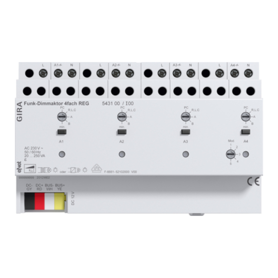
Wireless dimming actuator, 4-gang
Wireless dimming actuator, 4-gang
Order no.: 5431 00
Operating instructions
1
Safety instructions
Electrical devices may only be mounted and connected by electrically skilled persons.
Serious injuries, fire or property damage possible. Please read and follow manual fully.
Danger of electric shock. Always disconnect before carrying out work on the device or load. In
so doing, take all the circuit breakers into account, which support dangerous voltages to the
device and or load.
Danger of electric shock. Device is not suitable for disconnection from supply voltage. The load
is not electrically isolated from the mains even when the device is switched off.
Danger of electric shock. During installation and cable routing, comply with the regulations and
standards which apply for SELV circuits.
Risk of destruction if the set operating mode and load type do not match. Set correct operating
mode when connecting or exchanging the load.
Fire hazard. For operation with inductive transformers, each transformer must be fused on the
primary side in accordance with the manufacturer's instructions. Only safety transformers ac-
cording to EN 61558-2-6 may be used.
Fire hazard! Operation exclusively with the power supplies listed under accessories
These instructions are an integral part of the product, and must remain with the end customer.
2
Intended use
–
Switching and dimming of lighting
–
Operation with power supply RMD and receiver module RMD cover or eNet server (see
accessories)Operation with power supply RMD and receiver module RMD cover or eNet
server (see accessories)
–
Operation with suitable radio transmitters
–
Installation in small distributors on DIN rail according to EN 60715
Product characteristics
–
Switch-on via bulb-preserving soft start
–
Switch-on brightness for each output can be saved permanently
–
Minimum brightness for each output can be saved permanently
–
Scene operation possible
–
Status indicator of the outputs via LED
–
Status feedback to radio transmitter
–
Outputs switchable with Prog button
–
Increase in output power possible through parallel switching of multiple outputs
–
Electronic short-circuit protection with permanent switch-off after 7 seconds at the latest
–
Electronic over-temperature protection
–
Automatic or manual setting of the dimming principle suitable for the load
–
Power extension possible by means of power boosters
Can be set with eNet server:
–
Maximum brightness
–
Dimming speed
–
Switch-on delay / switch-off delay
–
Dim up/dim down ramp
32578622
10867484
01.10.2019
1 / 19
Advertisement
Table of Contents

Related Manuals for Gira 5431 00


Summary of Contents for Gira 5431 00
- Page 1 Wireless dimming actuator, 4-gang Wireless dimming actuator, 4-gang Order no.: 5431 00 Operating instructions Safety instructions Electrical devices may only be mounted and connected by electrically skilled persons. Serious injuries, fire or property damage possible. Please read and follow manual fully.
-
Page 2: Operation
Wireless dimming actuator, 4-gang – Switch-off warning – Operation locks – Continuous on, Continuous off – Hotel function – Run-on time – Light control Supplementary functions with eNet Server: – Fully encrypted radio transmission (AES-CCM) from eNet Server software version 2.0 –... - Page 3 Wireless dimming actuator, 4-gang Fitting the device Observe the temperature range. Ensure adequate cooling. Maintain a distance of 18 mm (1 module) between the devices when operating multiple dimmers or power units within a sub-division. ■ Mount device on DIN rail. Output terminals must be at the top. Connect bus line Figure 1: Connection diagram of bus line Labelling / Colour...
- Page 4 Wireless dimming actuator, 4-gang Connecting loads to outputs Figure 2: Connection example of outputs Load connection A1...A4 Operating mode switch A1...A4 Button Prog A1...A4 Status LED A1...A4 Switch Mod. Bus line connection Set Mod. switch (5) to position 1. ■ All load outputs work independently of each other. Connect 600 Watt LED lamps or compact fluorescent lamps at most per 16 ampere circuit breaker.
- Page 5 Wireless dimming actuator, 4-gang Switching outputs in parallel Two to four load outputs can be switched in parallel for the power booster. The output with the lowest number is the master output, the allocated outputs work as slave. The operation, setting of the operating mode, basic brightness, switch-on brightness and parameters takes place only on the master output.
- Page 6 Wireless dimming actuator, 4-gang Figure 4: Connection example with two parallel outputs each Do not connect any LED lamps or compact fluorescent lamps to outputs switched in par- allel. Do not connect electronic and inductive Transformers together to outputs switched in par- allel.
- Page 7 Wireless dimming actuator, 4-gang Switch position Function/connectable loads ciple, dimmable HV-LED or compact fluorescent lamps that can be dimmed according to the trailing edge phase control principle. The connection of inductive transformers is not per- mitted. min. Setting of the minimum brightness If the operating mode switch is turned from the position PC, the operating mode and parameters are set to the default setting.
-
Page 8: Technical Data
Wireless dimming actuator, 4-gang The status LED (4) flashes quickly for 5 seconds. The output is disconnected from the ra- dio transmitter. The output and radio transmitter exit the programming mode automatic- ally. If there several connections or scene buttons for a radio transmitter, all connections must be disconnected individually. -
Page 9: Parameter List
Wireless dimming actuator, 4-gang For ohmic-inductive mixed load, maximum 50% proportion of ohmic load. Otherwise in- correct calibration of the dimmer may result. Only subject load outputs switched in parallel to up to 95%. The minimum load of parallel switching of load outputs is 250 VA. Figure 6: Connected load If the operating mode is set to HV { LED trailing edge phase control, the maximum connected load for LED lamps increases to typ. - Page 10 Wireless dimming actuator, 4-gang Parameters Setting options, Basic setting Explanations Operating mode Normal operation Normal operation Continuous on The output can be operated Continuous off with radio transmitters and the Basic setting: Normal Opera- Prog button. tion Continuous on The output switches to con- tinuously "On".
- Page 11 Wireless dimming actuator, 4-gang Parameters Setting options, Basic setting Explanations Maximum brightness 75...100 % Specifies the maximum set- Basic setting: 100 % table brightness. Note: If parameters or scene values are set to a level higher than the maximum brightness, then the system will dim to maximum brightness.
- Page 12 Wireless dimming actuator, 4-gang Parameters Setting options, Basic setting Explanations transmitters (short operation). If scenes are recalled or switching uses logic modules, the system switches off dir- ectly. Run-on time 0 s … 24 h As soon as a run-on time has Basic setting: 0 s been entered, the actuator will no longer remain on perman-...
- Page 13 Wireless dimming actuator, 4-gang Parameters Setting options, Basic setting Explanations Dimming principle Universal Specifies the dimming prin- LED leading edge phase con- ciple for the selected output. trol LED trailing edge phase con- Universal trol Automatic calibration to the Leading edge phase control load, dimming principle, lead- Trailing edge phase control ing edge phase control or trail-...
- Page 14 Wireless dimming actuator, 4-gang Parameters Setting options, Basic setting Explanations Brightness on voltage return 0...100 % Brightness value, set by the Basic setting: 100 % output after voltage return (mains voltage). The para- meter "Behaviour after voltage return" must be set to "Con- figured position".
- Page 15 Wireless dimming actuator, 4-gang Parameters Setting options, Basic setting Explanations Deactivate lock-out protection 0…100 % Defines the behaviour of the brightness value Basic setting: 0 % output on deactivating the lock-out protection. Only vis- ible when the priority for the lock-out protection is 0.
- Page 16 Wireless dimming actuator, 4-gang Parameters Setting options, Basic setting Explanations Switch off brightness over- On, Off Allows automatic switch-off shoot Basic setting: On according to the brightness. If the parameter is On, then the light controller switches off automatically when the bright- ness setpoint is greatly ex- ceeded.
-
Page 17: Troubleshooting
Wireless dimming actuator, 4-gang Troubleshooting Connected LED lamps or compact fluorescent lamps switch off in the lowest dimming position or flicker Cause: The set minimum brightness is too low. Increase minimum brightness. Connected LED lamps or compact fluorescent lamps flicker Cause 1: Lamps are not dimmable. -
Page 18: Warranty
The warranty is provided in accordance with statutory requirements via the specialist trade. Please submit or send faulty devices postage paid together with an error description to your re- sponsible salesperson (specialist trade/installation company/electrical specialist trade). They will forward the devices to the Gira Service Center. 32578622 10867484 01.10.2019... - Page 19 Wireless dimming actuator, 4-gang Gira Giersiepen GmbH & Co. KG Elektro-Installations- Systeme Industriegebiet Mermbach Dahlienstraße 42477 Radevormwald Postfach 12 20 42461 Radevormwald Deutschland Tel +49(0)21 95 - 602-0 Fax +49(0)21 95 - 602-191 www.gira.de info@gira.de 32578622 10867484 01.10.2019 19 / 19...
Need help?
Do you have a question about the 5431 00 and is the answer not in the manual?
Questions and answers