
Related Manuals for Hach Met One 6000 Series


Summary of Contents for Hach Met One 6000 Series
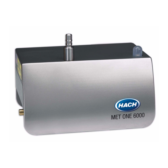
- Page 1 701246 Met One 6000 Series Particle Counter USER MANUAL March 2009, Edition 2 © HACH Company, 2009. All rights reserved. Printed in the U.S.A. jk/kt...
-
Page 3: Table Of Contents
Table of Contents Section 1 Specifications ........................3 Section 2 General information ......................5 2.1 Safety information ........................5 2.1.1 Use of hazard information....................5 2.1.2 Precautionary labels ......................5 2.1.3 Class 1 LASER ........................6 2.2 Configuration options ........................6 2.3 General product information ...................... - Page 4 Table of Contents 4.3.1.4 Network configuration....................40 4.3.1.5 Wireless LED indicators ...................40 4.4 Firmware update ........................41 Section 5 Maintenance ........................43 5.1 Maintenance schedule .......................43 5.2 Cleaning the instrument ......................43 5.2.1 Wipe down.........................43 5.2.2 Zero counting........................43 5.2.3 Purging ..........................44 5.3 Tubing replacement........................44 5.4 Calibration ..........................44 Section 6 Troubleshooting ......................45...
-
Page 5: Section 1 Specifications
Section 1 Specifications Specifications are subject to change without notice. Instrument Light source Long Life Laser™ diode Weight 0.82 kg (1.8 lb) Dimensions (W x D x H) 13.56 cm x 8.93 cm x 12.06 cm (5.34 in. x 3.52 in. x 4.75 in.) (refer to Figure Enclosure 304 stainless steel... - Page 6 Specifications Model 6003: 50% (± 20%) for 0.3 µm, (100% ± 10% at 1.5 times the minimum sensitivity). Fully complies with ISO21501-4. Model 6005: 50% (± 20%) for 0.5 µm, (100% ± 10% at 1.5 times the minimum Counting efficiency sensitivity).
-
Page 7: Section 2 General Information
Section 2 General information The contents of this manual is thought to be accurate. The manufacturer is not liable for direct, indirect, special, incidental or consequential damages resulting from any defect or omission in this manual, even if advised of the possibility of such damages. In the interest of continued product development, the manufacturer reserves the right to make improvements in this manual and the products it describes at any time, without notice or obligation. -
Page 8: Class 1 Laser
Specify the type of serial I/O configuration with an additional part number. RS232 = 20888600-232; RS485 = 20888600-485; Pulse = 20888600-PLS. This additional part number must be ordered for each counter (at no additional cost). Contact a Hach customer service representative for wireless availability in the country where the counter is located. -
Page 9: General Product Information
General information 2.3 General product information Figure 3 shows a diagram of the Met One 6000 particle counter. The remote airborne particle counters use a laser diode light source and collection optics for particle detection. The air quality of a clean room can be monitored by placing multiple particle counters at specific locations in the room. -
Page 10: Theory Of Operation
General information Table 1 LED indicator description LED color Indication System status Green Flashing (3 second) Normal operation sampling Green Steady Normal operation not sampling Solid or flashing Count alarm Blue Steady Sensor failure Blue Flashing Communication failure Blue One short flash, one long flash Flow failure Important Note: A yellow LED can be activated from the central monitoring software with ModBus protocol to flash for count alert. -
Page 11: Country-Specific Approval For Wi-Fi Device
Hach Company and its vendors will not be liable for any indirect, special, incidental or consequential damages caused by the breach in network security even if Hach Company or its vendors has been given advanced notice of the possibility of such damages. - Page 12 General information Harmonized countries approved for operation - ISO country codes Country ISO31662 letter code Austria Belgium Denmark Finland France Germany Greece Hungary Ireland Italy Mexico Poland Portugal Spain Sweden United Kingdom Iceland Norway Switzerland Turkey Netherlands Regulatory RF Device Approvals: FCC: Approved as a Modular Device under a TCB Grant of Authorization.
-
Page 13: Section 3 Installation
Section 3 Installation Important Note: Approved personnel only must install or commission the equipment. 3.1 Component list Compare each item in Figure 5 to the items in the shipment. Keep the packaging materials to use when the counter is sent to the factory for calibration. If an item is missing or damaged, contact the manufacturer. -
Page 14: Installation Overview
Installation 3.2 Installation overview The tasks that follow are necessary to install the particle counter (refer to Figure 1. Install the counter on a flat surface or a wall (section 3.4.1 on page 2. Install the vacuum tubing (section 3.4.2 on page 3. -
Page 15: Installation Guidelines
Installation 3.3 Installation guidelines Important Note: Stop the vacuum pump and put a cover on the sample inlet connection before a cleaning or disinfecting cycle is started. Refer to the following general guidelines during installation. • If the room is washed down at regular intervals, install the counter outside of the room. Only the intake and vacuum tubes will go into the clean room. -
Page 16: Tubing Installation
Installation Prerequisites: DIN rail kit (refer to Parts and accessories on page 47). Kit contents: • DIN rail section, approximately 6 in. length • 2 clips • 2 clip screws Installation procedure: Complete the following steps to install the particle counter with the DIN rail kit. 1. - Page 17 Installation Prerequisites: ® ® • Sample tubing—Hytrel Bevaline, Tygon or equivalent • Vacuum tubing—Hytrel Bevaline, Tygon or equivalent • Tubing hooks or cable ties Installation procedure: Important Note: Do not connect the vacuum tube to the vacuum source until the room is ready for sampling.
-
Page 18: Sample Probe Installation
Installation 3.4.3 Sample probe installation The sample probe must be installed correctly to prevent contamination of the counter and to get a representative sample of the area. 3.4.3.1 Sample probe kits The following optional kits are available for installing the sampling probe. Refer to Figure 9 Parts and accessories on page 47 for order information. -
Page 19: Sample Probe Guidelines
Installation 3.4.3.2 Sample probe guidelines The position of an isokinetic probe is very important for count accuracy. Refer to the sampling guidelines and Figure 4 on page 9 before installation. Sampling guidelines • Keep the sample probe a minimum of 12 inches from loose materials, dust, liquids and sprays. -
Page 20: Electrical Installation
Installation 3.6 Electrical installation Refer to the following sections for the communication option that is used: • RS485 (section 3.6.3 on page • RS232 (section 3.6.4 on page • Pulse (section 3.6.5 on page • Ethernet (section 3.6.6 on page •... - Page 21 Installation Table 2 Terminal assignments—RS485 output Terminal Assignment RS485 A RS485 B RS485 A RS485 B Pump TD Pump RD Common (shield ground) Power source (9–28 VDC, 1 A maximum) Common Network wiring RS485 (EIA-485) supports up to 32 instruments (12 K load each). Use a high grade wire for serial communications such as Belden 9841.
-
Page 22: Rs232 Wiring
Installation 3.6.4 RS232 wiring Refer to Figure 12 Table 3 to install a particle counter with RS232 communication. Figure 12 Terminal assignments—RS232 communication Table 3 Terminal assignments—RS232 output Terminal Assignment (not used) (not used) RS232 TX RS232 RX Pump TD Pump RD Common (shield ground) Power source (9–28 VDC, 1 A maximum) -
Page 23: Ethernet Wiring
Installation Figure 13 Wiring for pulse output Table 4 Terminal assignments—pulse output Terminal Assignment Ch 1+ Ch 1– Ch 2+ Ch 2– Status + Status – Common (shield ground) Power source (9–28 VDC, 1 A maximum) Common 3.6.6 Ethernet wiring Ethernet standard 10Base-T or 100Base-T can be used, however the facility wiring must be appropriate for the speed of the network to prevent intermittent problems from occurring. -
Page 24: Wireless Installation
Note: Changes or modifications to this device not explicitly approved by Hach Company will void the user's authority to operate this device. No extra wiring is required for Wireless installation beyond the instrument power connection. -
Page 25: Analog Wiring
Installation devices that can cause RF interference to the instrument such as microwave ovens, arc welders, motors, and other industrial machinery. Use lower data rates when necessary to increase the operating range. For good margin, the instrument should be able to communicate at twice the required distance. - Page 26 Installation Table 6 Terminal assignments—analog output (continued) Terminal Assignment Channel 4 loop out Pump TD Pump RD Common (shield ground) Power source (9–28 VDC, 1 A maximum) Common When using a +24 V power supply as shown in Figure 16, the power supply can also be used as the 4–20 mA loop power source if there is enough operating overhead to drive the loop.
-
Page 27: Setting The Analog Scaling
Installation Figure 17 Maximum limit for current loop operation 3.6.9 Setting the analog scaling 1. Go to the Local Setup tab of the Setup Utility and click READ INSTRUMENT (Figure 18). Figure 18 Setup Utility, Local Setup tab—analog unit... -
Page 28: Testing Analog Output
Installation 2. Set the full-scale counts in the Analog section. The instrument default is 1000 for all four channels. Each channel can be individually set and is independent of the other. The analog outputs are updated at the end of each sample period. When an instrument is first powered on, all outputs are set to 4 milliamps. - Page 29 Installation 3. Allow a tiny amount of particles to flow through the instrument enough to get a count in the test channel. Note: One method to generate counts is to use a zero count filter, and put a pin-hole in the tubing that is between the filter and the instrument.
-
Page 30: Flow Alarm Test
Installation 3.6.10.2 Flow alarm test For units with a flow monitor, temporarily remove the central vacuum from the unit. The measured voltage can be found from equation (2): × Voltage < 0.002 RL where: RL = value of the load resistor in ohms Example: for a 100-ohm resistor, this voltage should be less than 0.20 volts. -
Page 31: Section 4 Operation
Section 4 Operation Each particle counter must be configured before operation for parameters such as sample time and count alarm thresholds. 4.1 Configure the particle counter A setup utility program is used to configure parameters that are stored in the particle counter. -
Page 32: Utility Program Operation
Operation 4.1.2 Utility program operation Complete the following steps to configure the particle counter. 1. Open the SetupUtility.exe file. The utility program will open (refer to Figure 21). 2. Find the Comport field. If necessary, change the COM port to match the port on the PC that the particle counter is connected to. - Page 33 Operation Figure 21 Setup utility program—non wireless units...
-
Page 34: Particle Counter Communication
Operation Figure 22 Setup utility program—wireless units 4.2 Particle counter communication Each Met One 6000 particle counter is assembled with one of the following communications formats: • RS485 communications—Modbus RTU (section 4.2.1 on page 32) or FXB protocol (Appendix B on page •... - Page 35 Operation Met One 6000 counters with the RS485 Modbus communication option use industry-standard Modbus RTU protocol. In this communication mode, a series of registers hold data about measurement results and operation parameters. The parameters are preset by the user through a utility setup program or through the central monitoring software.
-
Page 36: Ethernet With Modbustcp Protocol
Operation Address 0 can only be used with FX B protocol. If address 0 is set with Modbus protocol, the instrument will use address 1. 4.2.2 Ethernet with ModbusTCP protocol Important Note: The network should be set up by a network professional. After the network is set up, the counter can be configured through the network (operational) settings. -
Page 37: Lan Setup
Operation 4.2.2.1 LAN setup For configuration through a network, only the LAN settings can be changed. All other settings must be changed through local setup by direct connection to the service port on the counter or through a ModbusTCP connection. 1. -
Page 38: Ethernet Led Indicators
Operation 4.2.2.2 Ethernet LED indicators Refer to Table 10 for a description of the Ethernet connection LED indicators. Table 10 LED indicators for Ethernet LED color On/Off Indicator Yellow Connected Green 10Base-T Green 100Base-T 4.2.3 Pulse output modes The pulse unit sends an 8-µs signal each time a particle is detected. A data acquisition system installed by the user and connected to an output channel counts the pulses. -
Page 39: Analog Output
Network and access point security is the sole responsibility of the customer using the wireless particle counters. Hach Company and its vendors will not be liable for any indirect, special, incidental or consequential damages caused by the breach in network security even if Hach Company or its vendors has been given advanced notice of the possibility of such damages. -
Page 40: Wireless Setup
Operation Table 11 Ethernet field description Field Description Default MAC Media access control: unique permanent hardware address Read only (read-only) Enables or disables static or dynamic IP addressing by connection to a DHCP server. When enabled, the counter will get an IP address and subnet mask automatically on power up. - Page 41 Operation Table 12 Wireless field description (continued) Field Description Default Service Set Identifier name used to identify the Wireless LAN to be used. The SSID should use standard alpha numeric characters and SSID 6000WIFI avoid punctuation, spaces, or other special characters. The SSID should be a minimum of 8 characters in length.
-
Page 42: Network Configuration
Operation 4.3.1.4 Network configuration Figure 28 LAN setup for Ethernet units Error messages If an error message such as "Invalid IP setting" is shown, refer to Table 11 to find the values that can be used. Enter a value in the range for the setting. 4.3.1.5 Wireless LED indicators Refer to Table 13... -
Page 43: Firmware Update
4.4 Firmware update The instrument can be updated with a newer version of firmware using the utility program. However, it is recommended that firmware is updated by a trained Hach Company service representative. Important note: Power loss during a firmware update can cause serious problems with the instrument. - Page 44 Operation Firmware update error If an error message is shown during the update, make sure that the instrument has power and that the instrument is connected to the correct port on the PC. Power failure during update If a power failure occurred during the update, complete the following procedure. 1.
-
Page 45: Section 5 Maintenance
Section 5 Maintenance Important Note: Do not disassemble the particle counter for maintenance. If the internal components require cleaning, contact the nearest Hach Company authorized service representative. 5.1 Maintenance schedule Complete the maintenance tasks according to the schedule in Table 14 to keep the particle counter operating efficiently. -
Page 46: Purging
The Met One 6000 particle counter must be returned to the service center for calibration (refer to Return procedures on page 49). Long-term instrument service contracts are available from Hach Company. Contact the nearest Hach Company sales or service representative for more information. -
Page 47: Section 6 Troubleshooting
Section 6 Troubleshooting 6.1 Troubleshooting table Table 15 for help with problems that may occur with the system. Table 15 Troubleshooting table Problem Possible causes Solution Examine the system for loose or incorrect Incorrect wiring connections Configure the counter using the setup utility Unit not configured Communication failure program... - Page 48 Troubleshooting...
-
Page 49: Section 7 Replacement Parts And Accessories
Section 7 Replacement parts and accessories 7.1 Parts and accessories Description Catalog Number Antenna for Wi-Fi counter 490-200-0001 Bracket, to mount RH/temperature probe 2088517 Bracket, to mount external LED light stack with isokinetic probe 2088480 Bracket, wall, for external LED light stack 2088482 Bracket, wall, for isokinetic probe 2082644-3... - Page 50 Replacement parts and accessories...
-
Page 51: Section 8 Contact Information
To return the Met One 6000 series Particle Counters for repair or calibration, first obtain a returned material authorization number (RA#). The RA# number is necessary for any instrument that requires repair or calibration by an authorized service center. - Page 52 Contact information...
-
Page 53: Section 9 Limited Warranty
Hach Company warrants the Long Life Laser™ diode to be free of defects in materials and workmanship for a period of three (3) years from the shipping date. If any diode... - Page 54 Limited warranty...
-
Page 55: Appendix A Modbus Register Maps
Appendix A Modbus register maps Important Note: The Modbus register tables in this section may become updated. Contact Hach Company for updated tables. This section describes the Modbus registers that are used to communicate with Met One 6000 series particle counters. These registers are applicable to units that have RS485 serial output with Modbus RTU protocol or Ethernet output with ModbusTCP protocol. -
Page 56: Counter Configuration
Modbus register maps A.2 Counter configuration The configuration data block (Table 17) has parameters that directly affect the sampling characteristics of the instrument. If a sample is active, any modifications to these registers will restart the current sample. Table 17 Configuration information Address Register description Access... -
Page 57: Data Label
Modbus register maps A.3 Data label Table 18 provides a register for sample and analog data labels. Table 18 Count bin data labels Address Register description Access Size (bytes) Data format Size 1 label 0.2–10.0 microns Size 2 label 0.2–10.0 microns Size 3 label 0.2–10.0 microns Size 4 label... -
Page 58: Buffered Sample Data
Modbus register maps Table 19 Sample data (continued) Address Register description Access Size (bytes) Notes 385–399 Expansion Sample alarm status Registers 309 and 509, sample status and buffered sample status, contain the sample alarm status (refer to Table 20 for an example). These alarms are bit-wise mapped. Table 20 Register 309 sample alarm status Address Status... -
Page 59: Buffered Record Block
Modbus register maps A.6 Buffered record block The buffered record block (Table 22) gives a remote application the ability to access data that is stored in the instrument. The block is continuously updated with new sample data. Table 22 Buffered record Address Register description Access... -
Page 60: Sample Mode Parameters
Modbus register maps A.7 Sample mode parameters The sample mode parameters register (Table 23) defines basic counting characteristics of a sample. Any updates to these registers will restart any active sample sequences. Table 23 Sample mode parameters Address Register description Access Size (bytes) Data format Number of count bins... -
Page 61: Sensor Calibration Information
Modbus register maps A.9 Sensor calibration information The sensor calibration information register is used for instruments that can electronically adjust the calibration circuitry or algorithm. The sensor information can be read from a plug and play sensor or can be loaded at the factory or by qualified field personnel. Table 25 Sensor calibration information Address Register description... -
Page 62: Ethernet Configuration
Modbus register maps A.12 Ethernet configuration Table 28 shows the register blocks for counters that have an Ethernet module. These settings will take affect when the settings have been saved and when the counter has been reset (refer to registers 1101 1103 section... -
Page 63: Last Sample Data
Modbus register maps Table 29 Wireless configuration (continued) Address Register description Access Size Notes 0-48 WPA/WPA2 or 1463 Key/Passphrase length 2 bytes 0-63 WEP 1464 Roaming 2 bytes Disabled, Enabled 1465-1472 Radio firmware version 16 bytes ASCII String 1473-1499 Expansion A.14 Last sample data Table 30 shows the register block mirrors of the real-time and buffered data register... - Page 64 Modbus register maps...
-
Page 65: Appendix B Fxb Communication
“00” and so on to 191 (BFh) equal to location “63”. Note: The valid range for most Hach Company software is from location “00” to “31.” Note: When using FX protocol, the serial record always reports counts in raw cumulative particles and flow in cfm. - Page 66 FXB communication Table 31 Request for data commands (continued) Command Description The counter will send an alphanumeric data string name label terminated by a "T" Identify Model carriage return and line feed. The "Name Label" field can vary in length. The counter will be placed in the "remote"...
-
Page 67: Command Responses
FXB communication Table 33 Universal action commands (continued) Command Description The counter(s) will start counting in either of the two preselected counting "ud" Universal Start Count modes (Auto or Manual). This command is not echoed. The counter(s) will stop counting and will build a data record. This command is "ue"... - Page 68 FXB communication Figure 29 Data record format examples of a 2 channel counter without flow sensor and a 4 channel sensor with flow and RH/Temp sensor Status ($ = count alarm) 12 Value Date 13 Tag Time 14 Count Period 15 Size Channel 1 16 Flow rate...
- Page 69 FXB communication Table 34 Data record element descriptions Information Description When translated to a binary byte, the status character indicates the status of the counter. As shown below, ASCII character "$" has a decimal value of 36, which when converted to a binary byte, sets the third and sixth (always 1) bits.
-
Page 70: Data Record Format Examples
FXB communication Table 34 Data record element descriptions (continued) Information Description Flow rate value shown in CFM. A value of 000100 equals .100 CFM. A value of 001000 Flow rate equals 1.000 CFM. Calibration value of the sensor. A value of 000100 equals a calibration voltage of 1.00 VDC. Calibration value Valid ranges are 0.80 to 1.20 VDC.
Need help?
Do you have a question about the Met One 6000 Series and is the answer not in the manual?
Questions and answers