
Related Manuals for Printronix P6000 Series


Summary of Contents for Printronix P6000 Series
- Page 1 All manuals and user guides at all-guides.com Maintenance Manual Volume 1 of 2 P6000 Series Pedestal Model...
- Page 2 All manuals and user guides at all-guides.com...
- Page 3 All manuals and user guides at all-guides.com P6000 Series Pedestal Model Maintenance Manual, Vol. 1 P/N 108692–001, Rev B Volume 1 of 2...
- Page 4 Printronix, Inc. makes no representations or warranties of any kind regarding this material, including, but not limited to, implied warranties of merchantability and fitness for a particular purpose. Printronix, Inc. shall not...
-
Page 5: Table Of Contents
All manuals and user guides at all-guides.com Table of Contents VOLUME 1 Paragraph Title Page CHAPTER 1. MAINTENANCE OVERVIEW Introduction ........... . Printer Description . -
Page 6: Title Page
All manuals and user guides at all-guides.com Table of Contents Paragraph Title Page CHAPTER 5. CORRECTIVE MAINTENANCE Section I. GENERAL Introduction ........... . Tools, Test Equipment, and Supplies . - Page 7 All manuals and user guides at all-guides.com 5-38 Paper Out Optical Sensor ......... 5-69 5-39 Platen Open Switch...
- Page 8 All manuals and user guides at all-guides.com List of Illustrations Figure Title Page Printer with Pedestal ..........External Controls and Indicators .
- Page 9 All manuals and user guides at all-guides.com List of Illustrations Figure Title Page Confidence Check ..........New Printer Does Not Operate .
- Page 10 All manuals and user guides at all-guides.com List of Illustrations Figure Title Page 5-10 Paper Feed Belt Tension Check and Adjustment ..... . 5-20 5-11 Paper Motion Sensor Check and Adjustment...
- Page 11 All manuals and user guides at all-guides.com ABOUT THIS MANUAL This manual has been organized and written to make it easy to use. The following information will help you use this P6040/P6080 Maintenance Manual. What This Manual Contains This manual contains the following information. Consult your table of contents to locate this infor mation.
- Page 12 All manuals and user guides at all-guides.com viii P6040/P6080 Maintenance...
-
Page 13: Chapter 1. Maintenance Overview
1-1. Introduction This manual contains information required to maintain and repair the Printronix P6040 and P6080 Printers (hereafter referred to as P6000 Series or simply, the printer). Print speed is the basic difference between printers. The following documents provide detailed information which supplements this manual: P6000 Series Multifunction Line Printer Pedestal Models Operator's Guide, P/N 108525-001 - Contains instructions for unpacking, installing, and operating the printer. -
Page 14: Printer Description
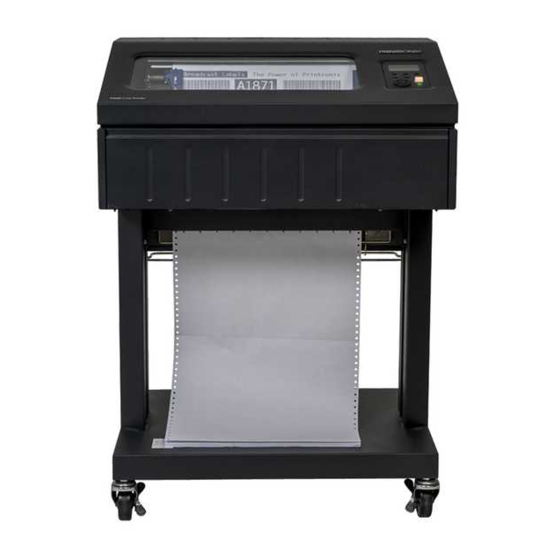
All manuals and user guides at all-guides.com 1-2. Printer Description -continued b. Standard Features -continued 9. Configuration Printout 10. Datastream Hex Code Printout 11. Resident Serial and Parallel Interfaces c. Optional Features. tbd P6040/P6080 Maintenance Overview... - Page 15 All manuals and user guides at all-guides.com Figure 1-1. Printer with Pedestal P6040/P6080 Maintenance Overview...
-
Page 16: Specifications
All manuals and user guides at all-guides.com 1-3. Specifications For a detailed list of printer specifications refer to the User's Reference Manual, P/N 108534-001. 1-4. Operation a. Operating Procedures For detailed operating procedures, refer to Operator's Guide, P/N 108525-001. b. Controls and Indicators External Controls and Indicators. - Page 17 All manuals and user guides at all-guides.com Table 1-1. External Controls and Indicators -continued CONTROL OR FUNCTION (FIG 1-2) INDICATOR CONFIG Cycles through configuration menus. MENU LINE Selects and causes display of current line spacing SPACING in lines per inch. FORMS Selects and causes display of current forms length LENGTH...
- Page 18 All manuals and user guides at all-guides.com Table 1-2. Internal Controls and Indicators CONTROL OR FUNCTION (FIG 1-3) INDICATOR Forms Thickness Sets platen for different thickness forms or paper. Adjustment Lever Opened (raised) fully for loading paper. Forms Thickness Indicates relative thickness of forms or paper. Scale and Pointer Tractors Used to set left margin and paper width.
- Page 19 All manuals and user guides at all-guides.com Figure 1-3. Internal Controls and Indicators P6040/P6080 Maintenance Overview...
- Page 20 All manuals and user guides at all-guides.com P6040/P6080 Maintenance Overview...
-
Page 21: Chapter 2. Principles Of Operation
Appendix B. Mnemonics are defined in Appendix A. 2-2. Purpose The P6000 Series printer is a computer output device. It receives data from a host computer and provides hard copy text or graphics. The hard copy is composed of an array of dots. In the case of text, these dots are arranged in a matrix to produce characters. - Page 22 All manuals and user guides at all-guides.com Figure 2-1. Defining the Dot Matrix UPPERCASE LOWERCASE UNDERLINE (REFERENCE) WITH DESCENDER Figure 2-2. Typical Characters WITH UNDERLINES WITHOUT UNDERLINES DOT COLUMN DOT COLUMN 1 3 5 7 9 1 3 5 7 9 DOT ROW DOT ROW ’...
- Page 23 The Hammer Bank In order to use matrix printing, you have to have a method to print the required dots. Printronix uses the hammer bank. The hammer bank contains a number of print hammers (44 for P6040; 66 for P6080) mounted on a shuttle that can move back and forth horizontally.
-
Page 24: Positioning And Release Of Odd And Even Hammers
All manuals and user guides at all-guides.com Figure 2-4. Positioning and Release of Odd and Even Hammers, P6080 P6040/P6080 Principles of Operation... -
Page 25: Hammer And Shuttle Arrangement (Typical)
All manuals and user guides at all-guides.com P6040 P6080 Figure 2-5. Hammer and Shuttle Arrangement (Typical) P6040/P6080 Principles of Operation... -
Page 26: Print Hammer Action
All manuals and user guides at all-guides.com P6040 P6080 Figure 2-6. Print Hammer Action P6040/P6080 Principles of Operation... - Page 27 All manuals and user guides at all-guides.com P6040 P6080 Figure 2-7. Standard Character Formation P6040/P6080 Principles of Operation...
- Page 28 All manuals and user guides at all-guides.com Figure 2-8. Character Formation by One Hammer P6040/P6080 Principles of Operation...
-
Page 29: Section Ii. Printer Function Elements
All manuals and user guides at all-guides.com Section II. PRINTER FUNCTIONAL ELEMENTS 2-4. General (Figures 2-9 and 2-10) The printer is made up of the following functional elements: n Control Panel n Logic C3 PCBA n Hammer Driver PCBA n Hammer Bank and Shuttle Mechanics/Magnetic Pickup (MPU) n Power Supply n Ribbon Drive n Paper Transport... - Page 30 All manuals and user guides at all-guides.com Figure 2-9. Printer Functional Elements 2-10 P6040/P6080 Principles of Operation...
- Page 31 All manuals and user guides at all-guides.com Figure 2-10. System Block Diagram P6040/P6080 Principles of Operation 2-11...
-
Page 32: Control Panel
All manuals and user guides at all-guides.com 2-5. Control Panel (Figures 2-11 and 2-12) The control panel consists of a power-on indicator, eleven momentary contact switches, an LCD alphanumeric display and an optional key-operated switch. The electrical interface to the logic C3 PCBA uses a communication scheme that does not require the direct use of the data or address bus. - Page 33 All manuals and user guides at all-guides.com Figure 2-11. Control Panel P6040/P6080 Principles of Operation 2-13...
- Page 34 All manuals and user guides at all-guides.com Figure 2-12. Control Panel Block Diagram 2-14 P6040/P6080 Principles of Operation...
- Page 35 All manuals and user guides at all-guides.com 2-6. Logic C3 PCBA (Figures 2-13 and 2-14) The logic C3 PCBA is the heart of the printer. It receives input data from the host computer, tem porarily stores it in DRAM, determines which hammers shall print and when, then outputs control and print signals to the hammer driver PCBA.
- Page 36 All manuals and user guides at all-guides.com Figure 2-13. Logic C3 PCBA 2-16 P6040/P6080 Principles of Operation...
- Page 37 All manuals and user guides at all-guides.com Figure 2-14. Logic C3 PCBA Block Diagram P6040/P6080 Principles of Operation 2-17...
- Page 38 All manuals and user guides at all-guides.com Table 2-1. Host Interface Connector Pin Assignments Mnemonic (Par/Serial) Description IBD1/RXDATA PARALLEL - Input Data Bit 1 SERIAL - Received data IBD2/DCD PARALLEL - Input Data Bit 2 SERIAL - Data carrier detect IBD3/DSR PARALLEL - Input Data Bit 3 SERIAL - Data set ready...
-
Page 39: Logic C3 Pcba
All manuals and user guides at all-guides.com 2-6. Logic C3 PCBA continued c. Power Supply Connector (J2) Refer to Table 2-2. Table 2-2. Power Supply Connector Pin Assignments Mnemonic Description Power, +5V Ground Shuttle Drive Enable +30V Power +30V Magnetic Pickup from Codewheel NPDE Paper Drive Enable Paper Motion Detect... - Page 40 All manuals and user guides at all-guides.com 2-6. Logic C3 PCBA continued d. Front Panel/Color Connector (J3) Presently, only the front panel interface of this connector is used. As such, only a 20-pin ribbon cable is connected to the 40-pin connector; however, Table 2-3 describes all of the connections. Table 2-3.
- Page 41 All manuals and user guides at all-guides.com 2-6. Logic C3 PCBA continued f. Expansion Connector (J5) Access is provided to the MC68000 microprocessor bus via an expansion connector located on the logic circuit card. The bus expansion mating connector is a 64-pin Cannon Part Number G06M64P3BLBL or equivalent with signals assigned as shown in Table 2-5.
- Page 42 All manuals and user guides at all-guides.com Table 2-5. Microprocessor Bus Expansion Connector Pin Assignment -continued Mnemonic Description Supply Voltage NADRDIS CPU Address Disable IPL1(O) Interrupt Priority Level 1 to CPU IPL0(O) Interrupt Priority Level 0 to CPU BR/NW Buffered Read/Not Write BSN5 Segment Line #5 BSN1...
- Page 43 All manuals and user guides at all-guides.com 2-6. Logic C3 PCBA continued g. Host Interfaces All three of the popular interfacing formats are available on the Logic C3. Only one can be active at a time, and different cables must be installed in order to activate each particular interface. There is one header associated with the host interface, located at 6A on the logic C3, the header must be installed per the logic C3 configuration drawing (108078).
- Page 44 All manuals and user guides at all-guides.com 2-6. Logic C3 PCBA continued i. Parallel Interfaces -continued The DMA must be set up for the transfer of data through channel 0. See table 2-6 for the DMA setup parameters. Table 2-6. DMA Parallel I/O Setup Parameters Register Hex Address Hex Data...
- Page 45 All manuals and user guides at all-guides.com 2-6. Logic C3 PCBA continued i. Parallel Interfaces -continued RDY - Ready 04014C RDY RESET 04014ERDY SET Active high signal indicates that the interface is ready to be placed online, should be sent during normal operation, and reset during check conditions.
- Page 46 All manuals and user guides at all-guides.com 2-6. Logic C3 PCBA continued i. Parallel Interfaces -continued The parallel port interrupt is input to the 68901 at GPIB4. DMA End (DEND) causes ICBUSY to go active, preventing further host data transfers. The DMA will only interrupt the processor when the byte count is zero, provided that the DEND/ IRQ enable bit is set (Interrupt Control Register Bit 0).
- Page 47 All manuals and user guides at all-guides.com 2-6. Logic C3 PCBA continued j. Mechanism Interface -continued Many signals from the printer are received by the logic C3 card through the J2 connector. The most important signal is MPU, since this is the signal which the software uses to synchronize the data to be printed with the mechanism.
- Page 48 All manuals and user guides at all-guides.com 2-6. Logic C3 PCBA continued n. Power Circuits The power supply generates +5V, GND, +30 V and -30V. Two other voltages are required that the power supply does not generate, +12V and -12V. These voltages are derived from the +30V and -30V available at J2 and are required for serial interface circuitry.
- Page 49 All manuals and user guides at all-guides.com 2-6. Logic C3 PCBA continued p. Front Panel Interface -continued ENABLE SET (PDATA input), to HI on front panel RESET NPLOAD RESET PCLK and write to NFDATAW port ($40084) eight times, then read from NFPDATA ($40084) for the high byte.
- Page 50 The power-on reset circuit, found on the page of the schematic with the CPU, has a reset time about 350ms. The P6000 Series power supply stabilizes +5V within 70ms after power-on. The 68000 requires that the reset line held low at least 170ms after +5V is stable.
- Page 51 All manuals and user guides at all-guides.com 2-6. Logic C3 PCBA continued s. Control Signals The control signals to and from the processor control the bus activity on the card. Several of the control signals on the 68000 are unused. The unused signals include: VPA, VMA, BERR, and E (1 MHz clock).
- Page 52 All manuals and user guides at all-guides.com 2-6. Logic C3 PCBA continued t. Address Bus Three address busses exist on the C3 card: the unbuffered address bus, A1-A23, the buffered ad dress bus BA1-BA23, and the memory address bus, MA0-MA7. Devices on the unbuffered address bus include: the 68000 MPU the 68B44 DMA, the 12L10 PAL and the 74ALS244 buffers.
- Page 53 All manuals and user guides at all-guides.com Table 2-8. Logic C3 Memory Map Address (A23-A0) Function Comments 00000 EPROM0 32Kx16 (27256) 00FFF 010000 EPROM1 32Kx16 (27256) 01FFFF 020000 EPROM2 32Kx16 (27256 02FFFF 030000 NO DECODE Not Implemented 03FFFF 040000 I/O SPACE See I/O Map for Details 04FFFF 050000...
- Page 54 All manuals and user guides at all-guides.com Table 2-9. Logic C3 I/O Address Map Address (A23-A0) Function Comments 040000 NMFPE 68901 Address Range 04003E 040040 NDMACS 68B44 Address Range 04007E UNLATCHED DECODE SIGNALS 040080 NHSTCNFW Match Char. Address 040082 NSTSOE Status Port 040084 NFPDATA...
- Page 55 All manuals and user guides at all-guides.com 2-6. Logic C3 PCBA continued Table 2-9. Logic C3 I/O Address Map -continued Address (A23-A0) Function Comments 04011C NHMRBLK RES Hammer Blank 04011E NHMRBLK SET Hammer Blank 040140 MCHACK RES Char Acknowledge 040142 MCHACK SET Char Acknowledge 040144...
- Page 56 All manuals and user guides at all-guides.com 2-6. Logic C3 PCBA continued z. DRAM There are 32K words (32K x 16) of DRAM on the logic C3. The 32K is divided up into two 16K blocks decoded as RAM0 and RAM1. Each 16K word block is built by using four 16K x 4 DRAM devices.
- Page 57 All manuals and user guides at all-guides.com Not all of the available 68901 MFP vectors are used. Table 2-11 defines unused vectors. Table 2-11. Logic C3 Unused Interrupt Vectors Vector (Hex) Definition Function Timer B Timer C Timer D GPIB1 GPIB 1 is configured as an I/O output port, DTR (Data Terminal Ready) to the Host.
- Page 58 2, 4 and 8 by a 74HC161. CLK2 is derived from the 20MHz signal and has the high est loading since this signal is used for many functions, it also drives circuits on the power supply in present P6000 Series printers. ac. Hardware Jumpers Table 2-12 briefly describes these jumpers.
- Page 59 All manuals and user guides at all-guides.com Table 2-12. Logic C3 Hardware Jumpers Software Jumper Description Readable Signal E1-E2 EPROM wait state jumper E3-E6 NTXCLK input E4-E7 NRXCLK input E5-E8 NEXT CLK input E6-E9 Clock to 68901 TC input E7-E10 Clock to 68901 RC input E8-E11 Timer C output to clock...
-
Page 60: Hammer Driver Pcba
All manuals and user guides at all-guides.com 2-7. Hammer Driver PCBA (Figure 2-15 through 2-17) Each of the print hammers (44 for P6040; 66 for P6080) is controlled by an electromagnetic coil, a driver, and a logic circuit which, among other functions, controls the energizing of the coil. The hammer logic circuits perform the following functions: Convert serial data bits (44 for P6040;... - Page 61 All manuals and user guides at all-guides.com Figure 2-15. Hammer Driver PCBA P6040/P6080 Principles of Operation 2-41...
- Page 62 All manuals and user guides at all-guides.com P6040 P6080 Figure 2-16. Hammer Driver Block Diagram 2-42 P6040/P6080 Principles of Operation...
- Page 63 All manuals and user guides at all-guides.com P6040 P6080 Figure 2-17. Hammer Driver Circuit Timing P6040/P6080 Principles of Operation 2-43...
-
Page 64: Hammer Bank And Shuttle Mechanism/Mpu
All manuals and user guides at all-guides.com 2-8. Hammer Bank and Shuttle Mechanics/MPU a. Hammer Bank Assembly/Shuttle Operation of the hammer bank is as described in paragraphs 2-3b and c. b. Magnetic Pickup (MPU) (Figures 2-18 and 2-19). Printing is synchronized with shuttle movement by the magnetic pickup (MPU) signal. The mag netic pickup, located next to the flywheel timing disk, is so oriented that timing signals relate pre cisely to the shuttle position. - Page 65 All manuals and user guides at all-guides.com P6040 P6080 Figure 2-18. Dot Row Timing vs Timing Disk and Cam Position P6040/P6080 Principles of Operation 2-45...
- Page 66 All manuals and user guides at all-guides.com Figure 2-19. Operation of MPU Circuit 2-46 P6040/P6080 Principles of Operation...
-
Page 67: Power Supply
All manuals and user guides at all-guides.com 2-9. Power Supply (Figure 2-20) a. P6040 The power supply assembly consists of chassis mounted transformer/rectifier/filter circuits and the power supply PCBA. AC line voltage is connected to the transformer at primary winding taps se lected for the line voltage in use. - Page 68 All manuals and user guides at all-guides.com P6080 Shown Figure 2-20. Power Supply 2-48 P6040/P6080 Principles of Operation...
-
Page 69: Power Supply
All manuals and user guides at all-guides.com 2-9. Power Supply -continued b. P6080 (Figures 2-20 and 2-21) The power supply assembly consists of chassis mounted transformer/rectifier/filter circuits and the power supply PCBA. The ac line voltage passes through one or both sides of a dual circuit breaker and appears at the transformer primary winding taps selected for the line voltage. - Page 70 All manuals and user guides at all-guides.com Figure 2-21. Power Supply Assembly, P6080 2-50 P6040/P6080 Principles of Operation...
-
Page 71: Power Supply
All manuals and user guides at all-guides.com 2-9. Power Supply -continued c. +36 V Supply, P6080 Only (Figure 2-22) A full wave rectifier consisting of half of the +70 Volt bridge and two SCRs rectifies the voltage from the +36 V winding. Each SCR controls the duration of current flow during one half cycle. A feedback circuit maintains a relatively constant pulsating dc voltage at the SCR cathodes. - Page 72 All manuals and user guides at all-guides.com Figure 2-22. +36 V and +70 V Supplies, P6080 2-52 P6040/P6080 Principles of Operation...
- Page 73 All manuals and user guides at all-guides.com Figure 2-23. Reference Voltage Circuit, P6080 P6040/P6080 Principles of Operation 2-53...
- Page 74 All manuals and user guides at all-guides.com Figure 2-24. +5 V and MOS Supplies, P6080 2-54 P6040/P6080 Principles of Operation...
- Page 75 All manuals and user guides at all-guides.com 2-9. Power Supply -continued j. Motor Relay Trigger, P6080 Only (Figures 2-25 and 2-26) The motor relay trigger is used to apply a high starting torque to the shuttle motor at rest and later disconnect the starting torque once the motor is running at the proper speed.
- Page 76 All manuals and user guides at all-guides.com Figure 2-25. Relay Switching Details, P6080 2-56 P6040/P6080 Principles of Operation...
- Page 77 All manuals and user guides at all-guides.com Figure 2-26. Motor Relay Trigger Circuit, P6080 P6040/P6080 Principles of Operation 2-57...
-
Page 78: Ribbon Drive
All manuals and user guides at all-guides.com 2-10. Ribbon Drive (Figures 2-27 through 2-29) The ribbon drive assembly contains two dc servomotors that move the ribbon continuously while there is shuttle action. One motor acts as the driver, drawing the ribbon against opposing torque exerted by the other motor. - Page 79 All manuals and user guides at all-guides.com Figure 2-28. Ribbon Drive P6040/P6080 Principles of Operation 2-59...
- Page 80 All manuals and user guides at all-guides.com Figure 2-29. Ribbon Control PCBA Simplified Schematic 2-60 P6040/P6080 Principles of Operation...
-
Page 81: Paper Feed Control Circuits
All manuals and user guides at all-guides.com 2-11. Paper Feed Control Circuits (Figures 2-30 and 2-31) The paper feed motor contains two pairs of coils, driven in sequence. As the electromagnetic detent locking the rotor is released, the rotor is advanced one increment, and the detent is set again. - Page 82 All manuals and user guides at all-guides.com Figure 2-31. Paper Feed Components 2-62 P6040/P6080 Principles of Operation...
-
Page 83: Platen Open/Paper Out Switches
All manuals and user guides at all-guides.com 2-12. Platen Open/Paper Out Switches (Figures 2-32 and 2-33) These switches signal the control panel that the printer is out of paper or the platen has been left open. When either signal is detected, paper transport is disabled. The signal faults are reported to the logic C3 through the control panel NFPFAULT switch. - Page 84 All manuals and user guides at all-guides.com Figure 2-32. Platen Open Switch 2-64 P6040/P6080 Principles of Operation...
- Page 85 All manuals and user guides at all-guides.com Figure 2-33. Paper Out Switch P6040/P6080 Principles of Operation 2-65...
-
Page 86: Safety Circuits, P6080 Only
All manuals and user guides at all-guides.com 2-13. Safety Circuits, P6080 Only (Figure 2-34) Excessive current and overheating can damage coils and hammer drivers in either of the following situations: Current turned on when not needed to release hammer springs. Current left on after hammer spring release. - Page 87 All manuals and user guides at all-guides.com 2-13. Safety Circuits -continued A fourth safety circuit halts hammer firing in the event of a hammer master clear, HMC, or the loss of the hammer reset pulse, HRS. When HMC is low, the output of the one millisecond one-shot, U16, is normally kept high while being triggered by HRS pulses.
-
Page 88: Section Iii. Operation
All manuals and user guides at all-guides.com Section III. Operation 2-14. Normal Operation (Figure 2-35) a. Character Printing During one cycle of normal operation, the printer is setup and put online by the operator, using the control panel. Host computer data is then read into the data input buffer. ASCII data from the input buffer is compared to tables stored in memory to determine the matrix locations to be printed for each character and build the dot image buffer. - Page 89 All manuals and user guides at all-guides.com Figure 2-35. Operation Flow Diagram P6040/P6080 Principles of Operation 2-69...
- Page 90 All manuals and user guides at all-guides.com 2-70 P6040/P6080 Principles of Operation...
-
Page 91: Chapter 3. Preventive Maintenance
All manuals and user guides at all-guides.com CHAPTER 3 PREVENTIVE MAINTENANCE 3-1. General This chapter provides instructions necessary to maintain the printer in operating condition. 3-2. Preventive Maintenance Checks and Service (PMCS) Printer PMCS are listed in Table 3-1. WARNING Remove power before performing PMCS. -
Page 92: Cleaning
All manuals and user guides at all-guides.com 3-4. Cleaning CAUTION Do not use abrasive cleaners, particularly on window. Do not drip water into printer. Damage to equipment will result. a. Exterior of Cabinet Wipe cabinet with clean, lint free cloth dampened (not wet) with water and mild deter gent. - Page 93 All manuals and user guides at all-guides.com Figure 3-1. Cleaning Interior of Cabinet P6040/P6080 Preventive Maintenance...
- Page 94 All manuals and user guides at all-guides.com 3-4. Cleaning -continued b. Interior of Cabinet -continued 5. Dislodge paper dust and ribbon lint with a soft brush. Vacuum up residue. Pay particular attention to tractor (7), hammer bank (8), and base pan (9). 6.
- Page 95 All manuals and user guides at all-guides.com 3-4. Cleaning -continued c. Hammer Bank Assembly -continued P6080 Only (a) Rotate hammer bank assembly (5) to operating position. (b) Place antirotation arm (4) in position. (c) Install two screws (3). Torque to 12 in-lbs. (d) Install comb bracket (2).
- Page 96 All manuals and user guides at all-guides.com 1. POWER CORD 2. FRONT COVER 3. FORMS THICKNESS LEVER 4. RIBBON LOCKS 5. RIBBON SPOOLS 6. RIBBON HUBS 7. SCREW, SOCKET HD (2) 8. RIBBON DRIVE ASSEMBLY 9. RETAINNG CLIP (2) 10. SUPPORT PIN, VERTICAL COVER 11.
- Page 97 All manuals and user guides at all-guides.com 1. SCREW 2. COMB BRACKET 3. SCREW (2) 4. ANTIROTATION ARM 5. HAMMER BANK 6. RIGHT TRACTOR 7. HAMMER BANK COVER 8. ROLL PINS 9. HAMMER SPRINGS 10. HAMMER TIPS 11. FILTER 12. BEARING BLOCK SCREW (2) P6080 Figure 3-3.
- Page 98 All manuals and user guides at all-guides.com NOTE: See Sheet 1 for Legend. P6040 Figure 3-3. Cleaning Hammer Bank Assembly - Hammer Bank to Service Position (2 of 2) P6040/P6080 Preventive Maintenance...
-
Page 99: Lubrication
All manuals and user guides at all-guides.com 3-5. Lubrication a. Counterweight and Cam Wick (Figure 3-4) 1. Gain access to counterweight and cam wick by performing steps 1 through 4 of paragraph 5-26. 2. Lubricate counterweight. (a) Using serrated, long nose pliers, pull out two oil port plugs (1). (b) Add one drop of SAE 20 oil to each port. - Page 100 All manuals and user guides at all-guides.com 1. OIL PORT PLUG (2) 2. CAM WICK 3. LEAF SPRING 4. CAM Figure 3-4. Lubrication, Counterweight and Cam Wick 3-10 P6040/P6080 Preventive Maintenance...
- Page 101 All manuals and user guides at all-guides.com 1. CAM 2. MAGNET BLOCK 3. RIGHT BEARING BLOCK 4. CAM FOLLOWER YOKE 5. PIN Figure 3-5. Lubrication, Self Aligning Cam Followers, P6080 Only P6040/P6080 Preventive Maintenance 3-11...
- Page 102 All manuals and user guides at all-guides.com 3-5. Lubrication -continued c. Antirotation Arm, P6040 Only (Figure 3-6) 1. Remove power cord (1). Open cover (2). Put ribbon drive to service position per para graph 3-4c4. 2. Remove two screws (3). 3.
- Page 103 All manuals and user guides at all-guides.com 1. POWER CORD 2. COVER 3. SCREW (2) 4. ANTIROTATION ARM 5. SPRING Figure 3-6. Lubrication, Antirotation Arm, P6040 Only P6040/P6080 Preventive Maintenance 3-13...
- Page 104 All manuals and user guides at all-guides.com 3-14 P6040/P6080 Preventive Maintenance...
-
Page 105: Chapter 4. Troubleshooting
4-1. General This chapter provides procedures to fault isolate to field replaceable units. A working knowledge of the P6000 Series Operator's Guide and the User's Reference Manual is required to perform fault isolation procedures contained in this chapter. 4-2. Common Causes of Malfunctions Improper printer operation may be caused by electronic failures, mechanical failures, or interface problems. -
Page 106: Confidence Check
All manuals and user guides at all-guides.com Table 4-1. Malfunction Symptom Index Flow Chart Malfunction Symptom Figure No I. UNSURE OF SYMPTOMS Confidence Check II. INITIAL INSTALLATION New Printer Does Not Operate III. CONTROL PANEL INDICATORS, SWITCHES, AND DISPLAYS OPERATE IMPROPERLY POWER Indicator Not Illuminated Error Indication on Display Stays On Online Not Indicated on Display... - Page 107 All manuals and user guides at all-guides.com Figure 4-1. Confidence Check (1 of 5) P6040/P6080 Troubleshooting...
- Page 108 All manuals and user guides at all-guides.com Figure 4-1. Confidence Check (2 of 5) P6040/P6080 Troubleshooting...
- Page 109 All manuals and user guides at all-guides.com Figure 4-1. Confidence Check (3 of 5) P6040/P6080 Troubleshooting...
- Page 110 All manuals and user guides at all-guides.com Figure 4-1. Confidence Check (4 of 5) P6040/P6080 Troubleshooting...
- Page 111 All manuals and user guides at all-guides.com Figure 4-1. Confidence Check (5 of 5) P6040/P6080 Troubleshooting...
- Page 112 All manuals and user guides at all-guides.com Figure 4-2. New Printer Does Not Operate P6040/P6080 Troubleshooting...
- Page 113 All manuals and user guides at all-guides.com Figure 4-3. POWER Indicator Not Illuminated (1 of 2) P6040/P6080 Troubleshooting...
- Page 114 All manuals and user guides at all-guides.com Figure 4-3. POWER Indicator Not Illuminated (2 of 2) 4-10 P6040/P6080 Troubleshooting...
- Page 115 All manuals and user guides at all-guides.com Figure 4-4. Error Indication on Display Stays On (1 of 2) P6040/P6080 Troubleshooting 4-11...
- Page 116 All manuals and user guides at all-guides.com Figure 4-4. Error Indication on Display Stays On (2 of 2) 4-12 P6040/P6080 Troubleshooting...
- Page 117 All manuals and user guides at all-guides.com Figure 4-5. Online Not Indicated on Display (1 of 2) P6040/P6080 Troubleshooting 4-13...
- Page 118 All manuals and user guides at all-guides.com Figure 4-5. Online Not Indicated on Display (2 of 2) 4-14 P6040/P6080 Troubleshooting...
- Page 119 All manuals and user guides at all-guides.com Figure 4-6. Shuttle Does Not Accelerate to Speed When ON LINE Switch is Pressed P6040/P6080 Troubleshooting 4-15...
- Page 120 All manuals and user guides at all-guides.com Figure 4-7. Ribbon Does Not Advance (1 of 2) 4-16 P6040/P6080 Troubleshooting...
- Page 121 All manuals and user guides at all-guides.com Figure 4-7. Ribbon Does Not Advance (2 of 2) P6040/P6080 Troubleshooting 4-17...
- Page 122 All manuals and user guides at all-guides.com Figure 4-8. Ribbon Folds Over 4-18 P6040/P6080 Troubleshooting...
- Page 123 All manuals and user guides at all-guides.com Figure 4-9. Ribbon Not Feeding Smoothly (1 of 2) P6040/P6080 Troubleshooting 4-19...
- Page 124 All manuals and user guides at all-guides.com Figure 4-9. Ribbon Not Feeding Smoothly (2 of 2) 4-20 P6040/P6080 Troubleshooting...
- Page 125 All manuals and user guides at all-guides.com Figure 4-10. End of Ribbon Not Detected P6040/P6080 Troubleshooting 4-21...
- Page 126 All manuals and user guides at all-guides.com Figure 4-11. Not Printing (1 of 3) 4-22 P6040/P6080 Troubleshooting...
- Page 127 All manuals and user guides at all-guides.com Figure 4-11. Not Printing (2 of 3) P6040/P6080 Troubleshooting 4-23...
- Page 128 All manuals and user guides at all-guides.com Figure 4-11. Not Printing (3 of 3) 4-24 P6040/P6080 Troubleshooting...
- Page 129 All manuals and user guides at all-guides.com Figure 4-12. Missing Characters (1 of 4) P6040/P6080 Troubleshooting 4-25...
- Page 130 All manuals and user guides at all-guides.com Figure 4-12. Missing Characters (2 of 4) 4-26 P6040/P6080 Troubleshooting...
- Page 131 All manuals and user guides at all-guides.com Figure 4-12. Missing Characters (3 of 4) P6040/P6080 Troubleshooting 4-27...
- Page 132 All manuals and user guides at all-guides.com Figure 4-12. Missing Characters (4 of 4) 4-28 P6040/P6080 Troubleshooting...
- Page 133 All manuals and user guides at all-guides.com Figure 4-13. Missing Characters, Example of P6040/P6080 Troubleshooting 4-29...
- Page 134 All manuals and user guides at all-guides.com Figure 4-14. Missing Dots (1 of 6) 4-30 P6040/P6080 Troubleshooting...
- Page 135 All manuals and user guides at all-guides.com Figure 4-14. Missing Dots (2 of 6) P6040/P6080 Troubleshooting 4-31...
- Page 136 All manuals and user guides at all-guides.com Figure 4-14. Missing Dots (3 of 6) 4-32 P6040/P6080 Troubleshooting...
- Page 137 All manuals and user guides at all-guides.com Figure 4-14. Missing Dots (4 of 6) P6040/P6080 Troubleshooting 4-33...
- Page 138 All manuals and user guides at all-guides.com Figure 4-14. Missing Dots (5 of 6) 4-34 P6040/P6080 Troubleshooting...
- Page 139 All manuals and user guides at all-guides.com Figure 4-14. Missing Dots (6 of 6) P6040/P6080 Troubleshooting 4-35...
- Page 140 All manuals and user guides at all-guides.com Figure 4-15. Missing Dots, Example of 4-36 P6040/P6080 Troubleshooting...
- Page 141 All manuals and user guides at all-guides.com Figure 4-16. Light and/or Smeared Characters (1 of 2) P6040/P6080 Troubleshooting 4-37...
- Page 142 All manuals and user guides at all-guides.com Figure 4-16. Light and/or Smeared Characters (2 of 2) 4-38 P6040/P6080 Troubleshooting...
- Page 143 All manuals and user guides at all-guides.com Figure 4-17. Light and/or Smeared Characters, Example of P6040/P6080 Troubleshooting 4-39...
- Page 144 All manuals and user guides at all-guides.com Figure 4-18. Misplaced Dots (1 of 4) 4-40 P6040/P6080 Troubleshooting...
- Page 145 All manuals and user guides at all-guides.com Figure 4-18. Misplaced Dots (2 of 4) P6040/P6080 Troubleshooting 4-41...
- Page 146 All manuals and user guides at all-guides.com Figure 4-18. Misplaced Dots (3 of 4) 4-42 P6040/P6080 Troubleshooting...
- Page 147 All manuals and user guides at all-guides.com Figure 4-18. Misplaced Dots (4 of 4) P6040/P6080 Troubleshooting 4-43...
- Page 148 All manuals and user guides at all-guides.com Figure 4-19. Print Too Light or Dark (1 of 2) 4-44 P6040/P6080 Troubleshooting...
- Page 149 All manuals and user guides at all-guides.com Figure 4-19. Print Too Light or Dark (2 of 2) P6040/P6080 Troubleshooting 4-45...
- Page 150 All manuals and user guides at all-guides.com Figure 4-20. Print Too Light or Dark, Example of 4-46 P6040/P6080 Troubleshooting...
- Page 151 All manuals and user guides at all-guides.com Figure 4-21. Horizontal Misalignment P6040/P6080 Troubleshooting 4-47...
- Page 152 All manuals and user guides at all-guides.com Figure 4-22. Horizontal Misalignment, Example of 4-48 P6040/P6080 Troubleshooting...
- Page 153 All manuals and user guides at all-guides.com Figure 4-23. Vertical Misalignment (1 of 4) P6040/P6080 Troubleshooting 4-49...
- Page 154 All manuals and user guides at all-guides.com Figure 4-23. Vertical Misalignment (2 of 4) 4-50 P6040/P6080 Troubleshooting...
- Page 155 All manuals and user guides at all-guides.com Figure 4-23. Vertical Misalignment (3 of 4) P6040/P6080 Troubleshooting 4-51...
- Page 156 All manuals and user guides at all-guides.com Figure 4-23. Vertical Misalignment (4 of 4) 4-52 P6040/P6080 Troubleshooting...
- Page 157 All manuals and user guides at all-guides.com Figure 4-24. Vertically Misaligned Character Position, Example of P6040/P6080 Troubleshooting 4-53...
- Page 158 All manuals and user guides at all-guides.com Figure 4-25. Vertically Deformed Characters, Example of 4-54 P6040/P6080 Troubleshooting...
- Page 159 All manuals and user guides at all-guides.com Figure 4-26. Vertical Compression of Print P6040/P6080 Troubleshooting 4-55...
- Page 160 All manuals and user guides at all-guides.com Figure 4-27. Garbled Letters and/or Wrong Font (1 of 2) 4-56 P6040/P6080 Troubleshooting...
- Page 161 All manuals and user guides at all-guides.com Figure 4-27. Garbled Letters and/or Wrong Font (2 of 2) P6040/P6080 Troubleshooting 4-57...
- Page 162 All manuals and user guides at all-guides.com Figure 4-28. No Paper Feed (1 of 4) 4-58 P6040/P6080 Troubleshooting...
- Page 163 All manuals and user guides at all-guides.com Figure 4-28. No Paper Feed (2 of 4) P6040/P6080 Troubleshooting 4-59...
- Page 164 All manuals and user guides at all-guides.com Figure 4-28. No Paper Feed (3 of 4) 4-60 P6040/P6080 Troubleshooting...
- Page 165 All manuals and user guides at all-guides.com Figure 4-28. No Paper Feed (4 of 4) P6040/P6080 Troubleshooting 4-61...
- Page 166 All manuals and user guides at all-guides.com Figure 4-29. Paper Feeds Erratically (1 of 5) 4-62 P6040/P6080 Troubleshooting...
- Page 167 All manuals and user guides at all-guides.com Figure 4-29. Paper Feeds Erratically (2 of 5) P6040/P6080 Troubleshooting 4-63...
- Page 168 All manuals and user guides at all-guides.com Figure 4-29. Paper Feeds Erratically (3 of 5) 4-64 P6040/P6080 Troubleshooting...
- Page 169 All manuals and user guides at all-guides.com Figure 4-29. Paper Feeds Erratically (4 of 5) P6040/P6080 Troubleshooting 4-65...
- Page 170 All manuals and user guides at all-guides.com Figure 4-29. Paper Feeds Erratically (5 of 5) 4-66 P6040/P6080 Troubleshooting...
- Page 171 All manuals and user guides at all-guides.com Figure 4-30. Paper Drags (1 of 3) P6040/P6080 Troubleshooting 4-67...
- Page 172 All manuals and user guides at all-guides.com Figure 4-30. Paper Drags (2 of 3) 4-68 P6040/P6080 Troubleshooting...
- Page 173 All manuals and user guides at all-guides.com Figure 4-30. Paper Drags (3 of 3) P6040/P6080 Troubleshooting 4-69...
- Page 174 All manuals and user guides at all-guides.com Figure 4-31. Top-of-Form Does Not Operate (1 of 2) 4-70 P6040/P6080 Troubleshooting...
- Page 175 All manuals and user guides at all-guides.com Figure 4-31. Top-of-Form Does Not Operate (2 of 2) P6040/P6080 Troubleshooting 4-71...
-
Page 176: Shift Recycle Test - Sliding Pattern
All manuals and user guides at all-guides.com 4-5. Performance Tests The following procedures describe tests to be performed with the Exerciser. Performance tests may also be performed using internal logic (see User's Reference Manual) or the host computer. These tests are helpful for checking print quality and verifying repairs. a. -
Page 177: Plot Pattern Test
All manuals and user guides at all-guides.com 4-5. Performance Tests -continued b. Plot Pattern Test (Figure 4-33) 1. Load printer with full-width, single-part paper. 2. Set Exerciser controls as follows: LINE LENGTH = 132 CHARACTER = DELETE SPECIAL = PLOT MODE FUNCTION = LINE FEED 3. -
Page 178: Mpu Phasing Test - All H's
All manuals and user guides at all-guides.com 4-5. Performance Tests -continued c. MPU Phasing Test - All Hs (Figure 4-34) 1. Load printer with full width single part paper. 2. Set Exerciser controls as follows: LINE LENGTH = 132 CHARACTER = H SPECIAL = NONE FUNCTION = LINE FEED 3. - Page 179 All manuals and user guides at all-guides.com 4-5. Performance Tests -continued d. Row Increment Test (Figure 4-35) 1. Load printer with full-width, single-part paper. 2. Set Exerciser controls as follows: LINE LENGTH = 132 CHARACTER = SR0-64 SPECIAL = ROW INC FUNCTION = LINE FEED 3.
-
Page 180: Underline/Vertical Hammer Alignment Test
All manuals and user guides at all-guides.com 4-5. Performance Tests -continued e. Underline/Vertical Hammer Alignment Test (Figure 4-36) 1. Load printer with full-width, single-part paper. 2. Set Exerciser controls as follows: LINE LENGTH = 132 CHARACTER = SPACE or DELETE SPECIAL = UNDERLINE FUNCTION - LINE FEED 3. - Page 181 All manuals and user guides at all-guides.com CHAPTER 5 CORRECTIVE MAINTENANCE Section I. GENERAL 5-1. Introduction Corrective maintenance at field level consists of mechanical alignments, adjustments, and re placement of printer subassemblies. a. Alignments and Adjustments Those items that may require field alignment or adjustment are listed below. 1.
- Page 182 All manuals and user guides at all-guides.com Table 5-1. Tools, Test Equipment, and Supplies PRINTRONIX RECOMMENDED ITEM PART NO. ITEM Adhesive 101537-001 Eastman 910 Oil, SAE 20 Adjustable Wrench Utica 91-4C Diagonal Cutters Erem 91EH Digital Voltmeter Exerciser, Pet Exerciser Cable, Centronics...
-
Page 183: Ribbon Height Adjustment
All manuals and user guides at all-guides.com Section II. ALIGNMENTS AND ADJUSTMENTS 5-3. Ribbon Height Adjustment (Figure 5-1) 1. Open front cover (1). 2. Remove ribbon spools (2) from hubs (3). 3. Check distance between bottom of hub (3) and gearbox (4). Hub should just clear gear box. - Page 184 All manuals and user guides at all-guides.com Figure 5-1. Ribbon Height Adjustment P6040/P6080 Corrective Maintenance...
- Page 185 All manuals and user guides at all-guides.com Figure 5-2. Ribbon Tracking Check and Adjustment P6040/P6080 Corrective Maintenance...
-
Page 186: Ribbon Tracking Check And Adjustment
All manuals and user guides at all-guides.com 5-4. Ribbon Tracking Check and Adjustment -continued 9. Allow all the ribbon to accumulate on left spool. On right ribbon guide (12) momentarily short across skids (13). 10. Perform step 8 for right ribbon guide. Allow all ribbon to run through guide and accumu late on right spool. - Page 187 All manuals and user guides at all-guides.com Figure 5-3. Shuttle Spring Force Adjustment P6040/P6080 Corrective Maintenance...
-
Page 188: Shuttle Spring Force Adjustment
All manuals and user guides at all-guides.com 5-5. Shuttle Spring Force Adjustment -continued 8. Install counterweight spring shim as follows: (a) Loosen screw (10) about three turns. (b) Press in on loosened screw (10) to create space for shim (11). (c) Install shim (11) between spring (6) and casting (12). - Page 189 All manuals and user guides at all-guides.com Figure 5-4. Setting Shuttle and Counterweight Preload P6040/P6080 Corrective Maintenance...
-
Page 190: Setting Shuttle And Counterweight Preload
All manuals and user guides at all-guides.com 5-6. Setting Shuttle and Counterweight Preload -continued b. Setting Preload Using Force Gauge -continued 7. Pull force gauge (1) horizontally to left. Note gauge indication when feeler gauge (3) comes loose. (a) If indication is between 10 and 16 pounds, go to step 8. (b) If indication is less than 10 pounds, install shuttle spring shim per paragraph 5-5 step 7 and repeat steps 5 through 7 above. - Page 191 All manuals and user guides at all-guides.com Figure 5-5. Hammer Spring Retensioning P6040/P6080 Corrective Maintenance 5-11...
-
Page 192: Hammer Tip Alignment
All manuals and user guides at all-guides.com 5-8. Hammer Tip Alignment (Figure 5-6) 1. Place ribbon drive in service position per paragraph 3-4c4. 2. Place hammer bank in service position per paragraph 3-4c5. 3. Loosen screw (1) of hammer (2) to be aligned. 4. - Page 193 All manuals and user guides at all-guides.com Figure 5-6. Hammer Tip Alignment P6040/P6080 Corrective Maintenance 5-13...
- Page 194 All manuals and user guides at all-guides.com Figure 5-7. Platen Gap Adjustment 5-14 P6040/P6080 Corrective Maintenance...
- Page 195 All manuals and user guides at all-guides.com 5-9. Platen Gap -continued 7. If platen (7) gap is incorrect: (a) Adjust two support bolts (9) as required. Note that 1/4 turn equals about 0.007 inch. (b) Repeat steps 5 through 7. 8.
-
Page 196: Magnetic Pickup Gap And Phasing Adjustment
All manuals and user guides at all-guides.com Figure 5-8. Magnetic Pickup Gap and Phasing Adjustment 5-16 P6040/P6080 Corrective Maintenance... - Page 197 All manuals and user guides at all-guides.com 5-11. Magnetic Pickup Phasing Adjustment (Figure 5-8) NOTE: Unless otherwise directed, perform gap adjustment, paragraph 5-10, before proceeding. 1. Loosen screw (6) until MPU arm (7) can be pivoted, but only with some effort. 2.
- Page 198 All manuals and user guides at all-guides.com 5-13. Shuttle Belt (Figure 5-9) a. Tension Check 1. Gain access to belt by performing steps 1-4 of paragraph 5-26a. 2. Observe belt (1) and press down in middle. 3. If belt deflection is significantly more or less than 0.25 inches, perform b below. b.
-
Page 199: Shuttle Belt Tension Check And Adjustment
All manuals and user guides at all-guides.com Figure 5-9. Shuttle Belt Tension Check and Adjustment P6040/P6080 Corrective Maintenance 5-19... - Page 200 All manuals and user guides at all-guides.com Figure 5-10. Paper Feed Belt Tension Check and Adjustment 5-20 P6040/P6080 Corrective Maintenance...
- Page 201 All manuals and user guides at all-guides.com 5-15. Paper Motion Sensor (Figure 5-11) a. Test 1. Verify that jumper enabling paper motion sensor is installed (see User's Reference Man ual). 2. Load paper and run several top-of-form operations. 3. Connect exerciser. Set exerciser to self-test and run several pages. Look for error mes sages.
- Page 202 All manuals and user guides at all-guides.com Figure 5-11. Paper Motion Sensor Check and Adjustment 5-22 P6040/P6080 Corrective Maintenance...
- Page 203 All manuals and user guides at all-guides.com 5-16. Paper Out Detectors (Figure 5-12) a. Mechanical Switch Check 1. With paper loaded and printer running, move Forms Thickness Lever to open. Paper mo tion should stop within two seconds. 2. With paper loaded and printer running, allow paper to run out. Paper motion should stop within two seconds.
- Page 204 All manuals and user guides at all-guides.com Figure 5-12. Paper Out Detector Adjustment 5-24 P6040/P6080 Corrective Maintenance...
- Page 205 All manuals and user guides at all-guides.com Section III. REPLACEMENT 5-17. Printer Cover (Figure 5-13) a. Removal 1. Disconnect power cord (1) and I/O cable (2). 2. Remove six screws (3). CAUTION Support rear door when opening. If allowed to fall unsupported, damage to printer may result.
-
Page 206: Cover Removal/Installation
All manuals and user guides at all-guides.com Figure 5-13. Cover Removal/Installation 5-26 P6040/P6080 Corrective Maintenance... - Page 207 All manuals and user guides at all-guides.com 5-18. Control Panel (Figure 5-14) a. Removal 1. Remove power cord (1). 2. Open front cover (2). 3. Remove four nuts (3) and washers (4). 4. Separate cover (5) from control panel (6). 5.
-
Page 208: Control Panel Removal/Installation
All manuals and user guides at all-guides.com Figure 5-14. Control Panel Removal/Installation 5-28 P6040/P6080 Corrective Maintenance... -
Page 209: Ribbon Drive
All manuals and user guides at all-guides.com 5-19. Ribbon Drive (Figure 5-15) a. Removal 1. Place ribbon drive assembly in service position per paragraph 3-4c4. 2. Check for labels on connectors at J1 (1), J2 (2), and J3 (3) and at ground wire (4). If not already labeled, install labels during removal (step 3 below). -
Page 210: Ribbon Drive Removal/Installation
All manuals and user guides at all-guides.com Figure 5-15. Ribbon Drive Removal/Installation 5-30 P6040/P6080 Corrective Maintenance... -
Page 211: Ribbon Control Pcba Removal/Installation
All manuals and user guides at all-guides.com Figure 5-16. Ribbon Control PCBA Removal/Installation P6040/P6080 Corrective Maintenance 5-31... - Page 212 All manuals and user guides at all-guides.com 5-21. Ribbon Drive Motor (Figure 5-17) a. Removal 1. Remove ribbon drive per paragraph 5-19a. 2. Loosen hub screw (1) and remove hub (2) from shaft of motor (3). 3. Disconnect motor cable connector (4) from ribbon control PCBA (5). Cut tie wraps as necessary to free cable.
-
Page 213: Ribbon Drive Motor Removal/Installation
All manuals and user guides at all-guides.com Figure 5-17. Ribbon Drive Motor Removal/Installation P6040/P6080 Corrective Maintenance 5-33... -
Page 214: Ribbon Drive Blower Removal/Installation
All manuals and user guides at all-guides.com Figure 5-18. Ribbon Drive Blower Removal/Installation 5-34 P6040/P6080 Corrective Maintenance... - Page 215 All manuals and user guides at all-guides.com 5-22. Ribbon Drive Blower -continued b. Installation 1. Install connector (5) in chassis (4). 2. Press blower (7) into place in chassis (4). 3. Connect short cable (6) to blower cable connector (5). 4.
-
Page 216: Shuttle Assembly Removal/Installation
All manuals and user guides at all-guides.com P6080 Figure 5-19. Shuttle Assembly Removal/Installation (1 of 2) 5-36 P6040/P6080 Corrective Maintenance... - Page 217 All manuals and user guides at all-guides.com P6040 Figure 5-19. Shuttle Assembly Removal/Installation (2 of 2) P6040/P6080 Corrective Maintenance 5-37...
- Page 218 All manuals and user guides at all-guides.com 5-23. Shuttle Assembly -continued b. Installation, P6080 NOTE: Before continuing, clean mating surfaces of casting and bearing blocks. 1. Set shuttle assembly (15) in position on printer (17) with antirotation arm (18) behind spring clip (19).
- Page 219 All manuals and user guides at all-guides.com 5-23. Shuttle Assembly -continued c. Removal, P6040 -continued 4. Remove screw (3), terminal lug (4), and star washer (5). 5. Loosen two screws (6) until shuttle (7) is free of base support (8). 6.
- Page 220 All manuals and user guides at all-guides.com 5-24. Hammer Spring (Figure 5-20) a. Removal 1. Place ribbon drive in service position per paragraph 3-4c4. 2. Place hammer bank assembly in service position per paragraph 3-4c5. 3. Clean hammer bank cover (1) with soft cloth moistened with isopropyl alcohol. 4.
-
Page 221: Hammer Spring Removal/Installation
All manuals and user guides at all-guides.com Figure 5-20. Hammer Spring Removal/Installation P6040/P6080 Corrective Maintenance 5-41... - Page 222 All manuals and user guides at all-guides.com 5-25. Hammer Coil (Figure 5-21) a. Removal, P6080 1. Place ribbon drive in service position per paragraph 3-4c4. 2. Loosen two comb bracket screws (1). Raise comb bracket (2) free of screws (1). 3.
- Page 223 All manuals and user guides at all-guides.com 5-25. Hammer Coil -continued b. Installation, P6080 -continued CAUTION Make sure leads lie at least 3/16 inch from clamp screws before tightening screws. Damage to leads, coils, or hammer drivers is possible. 7. Install wire clamp (7) and four screws (6). 8.
-
Page 224: Hammer Coil Removal/Installation
All manuals and user guides at all-guides.com P6080 Figure 5-21. Hammer Coil Removal/Installation (1 of 2) 5-44 P6040/P6080 Corrective Maintenance... - Page 225 All manuals and user guides at all-guides.com P6040 Figure 5-21. Hammer Coil Removal/Installation (2 of 2) P6040/P6080 Corrective Maintenance 5-45...
- Page 226 All manuals and user guides at all-guides.com 5-26. Counterweight Assembly (Figure 5-22) a. Removal 1. Remove power cord (1). 2. Open front cover (2). 3. Loosen two captive screws (3). 4. Remove cam cover (4) and attached gasket (5). 5. Remove five screws (6) and one shoulder screw (7). 6.
-
Page 227: Counterweight Assembly Removal/Installation
All manuals and user guides at all-guides.com Figure 5-22. Counterweight Assembly Removal/Installation (1 of 2) P6040/P6080 Corrective Maintenance 5-47... - Page 228 All manuals and user guides at all-guides.com Figure 5-22. Counterweight Assembly Removal/Installation (2 of 2) 5-48 P6040/P6080 Corrective Maintenance...
- Page 229 All manuals and user guides at all-guides.com 5-27. Flywheel Assembly (Figure 5-23) a. Removal 1. Remove counterweight assembly per paragraph 5-16a. CAUTION Do not adjust MPU clamp screw - it affects MPU gap. 2. Back out screw (1) about .25 inch. 3.
-
Page 230: Flywheel Assembly Removal/Installation
All manuals and user guides at all-guides.com Figure 5-23. Flywheel Assembly Removal/Installation 5-50 P6040/P6080 Corrective Maintenance... - Page 231 All manuals and user guides at all-guides.com 5-28. Cam Wick (Figure 5-24) a. Removal 1. Remove flywheel assembly per paragraph 5-27a. 2. Remove screw (1) and clip (2). 3. Remove wick (3) and inspect. Discard if necessary. b. Installation 1. Using a heavy cloth moistened with isopropyl alcohol, remove all metal shavings from fly wheel assembly (4) and housing (5).
-
Page 232: Cam Wick Removal/Installation
All manuals and user guides at all-guides.com Figure 5-24. Cam Wick Removal/Installation 5-52 P6040/P6080 Corrective Maintenance... -
Page 233: Magnetic Pickup Removal/Installation
All manuals and user guides at all-guides.com Figure 5-25. Magnetic Pickup Removal/Installation P6040/P6080 Corrective Maintenance 5-53... - Page 234 All manuals and user guides at all-guides.com 5-30. Shuttle Motor (Figure 5-26) a. Removal 1. Remove printer cover per paragraph 5-17a. 2. Loosen two screws (1). 3. Separate cam cover (2) and attached gasket (3) from housing (4). 4. Loosen four nuts (5). Allow motor (6) to slip down. 5.
-
Page 235: Shuttle Motor Removal/Installation
All manuals and user guides at all-guides.com Figure 5-26. Shuttle Motor Removal/Installation P6040/P6080 Corrective Maintenance 5-55... - Page 236 All manuals and user guides at all-guides.com 5-30. Shuttle Motor -continued b. Installation 1. Install pulley if required. (a) Position pulley (8) on adapter (23). (b) Install three screws (21) and washers (22). 2. Position motor (6) in printer (20). 3.
-
Page 237: Shuttle Belt Removal/Installation
All manuals and user guides at all-guides.com Figure 5-27. Shuttle Belt Removal/Installation P6040/P6080 Corrective Maintenance 5-57... - Page 238 All manuals and user guides at all-guides.com 5-32. Paper Ironer (Figure 5-28) a. Removal 1. Place ribbon drive assembly in service position per paragraph 3-4c4. 2. On P6080 only, loosen two comb clamp screws (1) and lift up comb clamp (2) to gain access to ironer mounting screws (3).
-
Page 239: Paper Ironer Removal/Installation
All manuals and user guides at all-guides.com Figure 5-28. Paper Ironer Removal/Installation P6040/P6080 Corrective Maintenance 5-59... -
Page 240: Paper Feed Belt Removal/Installation
All manuals and user guides at all-guides.com Figure 5-29. Paper Feed Belt Removal/Installation 5-60 P6040/P6080 Corrective Maintenance... - Page 241 All manuals and user guides at all-guides.com 5-33. Paper Feed Belt -continued b. Installation 1. Press bearing (6) against right side plate (7), but do not seat it. 2. Slip belt (10) onto spline shaft (5) by passing it over forms adjustment disk (12). 3.
-
Page 242: Paper Feed Motor Removal/Installation
All manuals and user guides at all-guides.com Figure 5-30. Paper Feed Motor Removal/Installation 5-62 P6040/P6080 Corrective Maintenance... - Page 243 All manuals and user guides at all-guides.com 5-35. Tractor (Figure 5-31) a. Removal 1. Remove power cord (1). Open cover (2). 2. Remove paper from printer. 3. Unlock right tractor (3) and left tractor (4). 4. Loosen setscrew (5). 5. Remove bushing (6) from spline shaft (7). 6.
-
Page 244: Tractor Removal/Installation
All manuals and user guides at all-guides.com Figure 5-31. Tractor Removal/Installation 5-64 P6040/P6080 Corrective Maintenance... - Page 245 All manuals and user guides at all-guides.com 5-35. Tractors -continued b. Installation - continued 2. To install right tractor: (a) Slide right tractor (3) onto support shaft (10). (b) Put support shaft (10) with both tractors (3 and 4) into printer. (c) Install spline shaft (10) into tractors (3 and 4).
-
Page 246: Paper Motion Sensor Removal/Installation
All manuals and user guides at all-guides.com Figure 5-32. Paper Motion Sensor Removal/Installation 5-66 P6040/P6080 Corrective Maintenance... - Page 247 All manuals and user guides at all-guides.com 5-36. Paper Motion Sensor -continued b. Installation 1. Connect cable (15) to sensor (14). 2. Place sensor (14) on tractor (4). 3. Install nut (10), star washer (11), washer (12), and retainer (13). 4.
-
Page 248: Paper Out Mechanical Switch Removal/Installation
All manuals and user guides at all-guides.com Figure 5-33. Paper Out Mechanical Switch Removal/Installation 5-68 P6040/P6080 Corrective Maintenance... -
Page 249: Paper Out Optical Sensor
All manuals and user guides at all-guides.com 5-38. Paper Out Optical Sensor (Figure 5-34) a. Removal 1. Remove printer cover per paragraph 5-17a. 2. Swing out card cage (1). 3. Remove two screws (2) and star washers (3). 4. Slide power supply (4) toward rear of printer to gain access to paper out switch assembly (5). -
Page 250: Paper Out Optical Sensor Removal/Installation
All manuals and user guides at all-guides.com Figure 5-34. Paper Out Optical Sensor Removal/Installation 5-70 P6040/P6080 Corrective Maintenance... -
Page 251: Platen Open Switch Removal/Installation
All manuals and user guides at all-guides.com Figure 5-35. Platen Open Switch Removal/Installation P6040/P6080 Corrective Maintenance 5-71... -
Page 252: Platen Open Switch
All manuals and user guides at all-guides.com 5-39. Platen Open Switch -continued b. Installation 1. Connect leads (3) to switch (4). 2. Place switch (4), spacer (5), and nut plate (6) on left side plate (7). 3. Install two screws (1) and washers (2). Do not tighten. 4. -
Page 253: Dc Power Supply Fuses Removal/Installation
All manuals and user guides at all-guides.com Figure 5-36. DC Power Supply Fuses Removal/Installation P6040/P6080 Corrective Maintenance 5-73... -
Page 254: Power Supply Pcba
All manuals and user guides at all-guides.com 5-41. Power Supply PCBA (Figure 5-37) a. Removal WARNING High electrical potentials may be present at power supply even with power disconnected. Exercise care; severe injury or death is possible. 1. Perform steps 1 through 5 of paragraph 5-40a. 2. -
Page 255: Power Supply Pcba Removal/Installation
All manuals and user guides at all-guides.com Figure 5-37. Power Supply PCBA Removal/Installation P6040/P6080 Corrective Maintenance 5-75... -
Page 256: Power Supply Removal/Installation
All manuals and user guides at all-guides.com Figure 5-38. Power Supply Removal/Installation 5-76 P6040/P6080 Corrective Maintenance... -
Page 257: Rear Fan
All manuals and user guides at all-guides.com 5-42. Power Supply -continued b. Installation 1. Place power supply assembly (11) on printer base (18). 2. Install screw (16) and terminal lug (17) at T1-7. 3. Install a screw (14) and terminal lug (15) at T1-1. 4. -
Page 258: Rear Fan Removal/Installation
All manuals and user guides at all-guides.com Figure 5-39. Rear Fan Removal/Installation 5-78 P6040/P6080 Corrective Maintenance... -
Page 259: Hammer Driver Pcba
All manuals and user guides at all-guides.com 5-44. Logic C3 PCBA (Figure 5-40) a. Removal 1. Loosen two fasteners (1). Allow rear door (2) to swing open. 2. Swing open card cage (3). 3. Remove tie wrap securing ejection lever (4). 4. -
Page 260: Logic Pcba Removal/Installation
All manuals and user guides at all-guides.com Figure 5-40. Logic PCBA Removal/Installation 5-80 P6040/P6080 Corrective Maintenance... -
Page 261: Hammer Driver Pcba Removal/Installation
All manuals and user guides at all-guides.com Figure 5-41. Hammer Driver PCBA Removal/Installation P6040/P6080 Corrective Maintenance 5-81... -
Page 262: Hammer Driver Pcba
All manuals and user guides at all-guides.com 5-45. Hammer Driver PCBA -continued b. Installation CAUTION Installing a PCBA in the wrong slot or backwards in the correct slot will damage PCBA and connector. 1. Slide PCBA (4) into correct slot in card cage (3). 2. -
Page 263: Hammer Bank Cable Harness Removal/Installation
All manuals and user guides at all-guides.com Figure 5-42. Hammer Bank Cable Harness Removal/Installation, P6080 Only (1 of 2) P6040/P6080 Corrective Maintenance 5-83... - Page 264 All manuals and user guides at all-guides.com Figure 5-42. Hammer Bank Cable Harness Removal/Installation, P6080 Only (2 of 2) 5-84 P6040/P6080 Corrective Maintenance...
- Page 265 All manuals and user guides at all-guides.com 5-46. Hammer Bank Cable Harness -continued b. Installation 1. Place hammer bank cable harness (28) in printer. 2. Place connector S2 (23) on casting (24). 3. Install two screws (21) and washers (22). 4.
- Page 266 All manuals and user guides at all-guides.com 5-86 P6040/P6080 Corrective Maintenance...
-
Page 267: Index
All manuals and user guides at all-guides.com INDEX Paragraph, Figure, Table Page Number +5 V and MOS Supplies ........F2-24 . - Page 268 All manuals and user guides at all-guides.com INDEX Paragraph, Figure, Table Page Number Cabinet, Cleaning Interior of ......3-4, F3-1 .
- Page 269 All manuals and user guides at all-guides.com INDEX Paragraph, Figure, Table Page Number DC Power Supply Fuse Replacement ..... 5-40, F5-36 .
- Page 270 All manuals and user guides at all-guides.com INDEX Paragraph, Figure, Table Page Number Garbled Letters and/or Incorrect Font ..... . . F4-27 .
- Page 271 All manuals and user guides at all-guides.com INDEX Paragraph, Figure, Table Page Number Jumpers, Logic C3 Hardware ....... T2-12 .
- Page 272 All manuals and user guides at all-guides.com INDEX Paragraph, Figure, Table Page Number New Printer Does Not Operate ......F4-2 .
- Page 273 All manuals and user guides at all-guides.com INDEX Paragraph, Figure, Table Page Number - continued PCBA Replacement Hammer Driver ........5-45, F5-41 .
- Page 274 All manuals and user guides at all-guides.com INDEX Paragraph, Figure, Table Page Number Rear Fan Replacement ....... . . 5-43, F5-39 .
- Page 275 All manuals and user guides at all-guides.com INDEX Paragraph, Figure, Table Page Number - continued Ribbon Folds Over ........F4-8 .
- Page 276 All manuals and user guides at all-guides.com INDEX Paragraph, Figure, Table Page Number Terms, Mnemonic ......... App A .
- Page 277 All manuals and user guides at all-guides.com...
- Page 278 All manuals and user guides at all-guides.com RINTRONIX 17500 C ARTWRIGHT 19559 92713-9559 RVINE, 714/863-1900 HONE: 714/660-8682 RINTRONIX EDERLAND OX 163, IEUWEWEG 283 NL-6600 A IJCHEN ETHERLANDS (31) 8894-90111 HONE: (31) 246-419768 RINTRONIX 512 C 02-15 ANE, EDOK NDUSTRIAL STATE 1646 INGAPORE (65) 449-7555...
- Page 279 All manuals and user guides at all-guides.com Maintenance Manual Volume 2 of 2 P6000 Series Pedestal Model...
- Page 280 All manuals and user guides at all-guides.com...
- Page 281 All manuals and user guides at all-guides.com P6000 Series Pedestal Model Maintenance Manual, Vol. 2 P/N 108692–001, Rev B Volume 2 of 2...
- Page 282 Printronix, Inc. makes no representations or warranties of any kind regarding this material, including, but not limited to, implied warranties of merchantability and fitness for a particular purpose. Printronix, Inc. shall not...
-
Page 283: Table Of Contents
All manuals and user guides at all-guides.com Table of Contents VOLUME 1 Paragraph Title Page CHAPTER 1. MAINTENANCE OVERVIEW Introduction ........... . Printer Description . - Page 284 All manuals and user guides at all-guides.com Table of Contents Paragraph Title Page CHAPTER 5. CORRECTIVE MAINTENANCE Section I. GENERAL Introduction ........... . Tools, Test Equipment, and Supplies .
-
Page 285: Title Page
All manuals and user guides at all-guides.com 5-38 Paper Out Optical Sensor ......... 5-69 5-39 Platen Open Switch... -
Page 286: Title Page
All manuals and user guides at all-guides.com List of Illustrations Figure Title Page Printer with Pedestal ..........External Controls and Indicators . -
Page 287: List Of Illustrations
All manuals and user guides at all-guides.com List of Illustrations Figure Title Page Confidence Check ..........New Printer Does Not Operate . -
Page 288: List Of Illustrations
All manuals and user guides at all-guides.com List of Illustrations Figure Title Page 5-10 Paper Feed Belt Tension Check and Adjustment ..... . 5-20 5-11 Paper Motion Sensor Check and Adjustment... - Page 289 All manuals and user guides at all-guides.com ABOUT THIS MANUAL This manual has been organized and written to make it easy to use. The following information will help you use this P6040/P6080 Maintenance Manual. What This Manual Contains This manual contains the following information. Consult your table of contents to locate this infor mation.
- Page 290 All manuals and user guides at all-guides.com viii P6040/P6080 Maintenance...
- Page 291 All manuals and user guides at all-guides.com APPENDIX A MNEMONIC TERMS P6040/P6080 Mnemonic Terms...
- Page 292 All manuals and user guides at all-guides.com The following list presents the mnemonics used in printer schematics. Mnemonics with initial let ter N" are negative true, all others are positive true. MNEMONIC DEFINITION 5 HL ....+5 Vdc for hammer Data Latches .
- Page 293 All manuals and user guides at all-guides.com NIONL ... . . Online NPDE ....Paper drive enables NRDY .
- Page 294 All manuals and user guides at all-guides.com P6040/P6080 Mnemonic Terms...
- Page 295 All manuals and user guides at all-guides.com P6040/P6080 Mnemonic Terms...
- Page 296 All manuals and user guides at all-guides.com P6040/P6080 Mnemonic Terms...
- Page 297 All manuals and user guides at all-guides.com APPENDIX B ELECTRONIC DRAWINGS P6040/P6080 Electronic Drawings...
- Page 298 All manuals and user guides at all-guides.com P6040/P6080 Electronic Drawings...
- Page 299 All manuals and user guides at all-guides.com P6040/P6080 Electronic Drawings...
- Page 300 All manuals and user guides at all-guides.com P6040/P6080 Electronic Drawings...
- Page 301 All manuals and user guides at all-guides.com P6040/P6080 Electronic Drawings...
- Page 302 All manuals and user guides at all-guides.com P6040/P6080 Electronic Drawings...
- Page 303 All manuals and user guides at all-guides.com P6040/P6080 Electronic Drawings...
- Page 304 All manuals and user guides at all-guides.com P6040/P6080 Electronic Drawings...
- Page 305 All manuals and user guides at all-guides.com P6040/P6080 Electronic Drawings...
- Page 306 All manuals and user guides at all-guides.com P6040/P6080 Electronic Drawings B-10...
- Page 307 All manuals and user guides at all-guides.com P6040/P6080 Electronic Drawings B-11...
- Page 308 All manuals and user guides at all-guides.com P6040/P6080 Electronic Drawings B-12...
- Page 309 All manuals and user guides at all-guides.com P6040/P6080 Electronic Drawings B-13...
- Page 310 All manuals and user guides at all-guides.com P6040/P6080 Electronic Drawings B-14...
- Page 311 All manuals and user guides at all-guides.com P6040/P6080 Electronic Drawings B-15...
- Page 312 All manuals and user guides at all-guides.com P6040/P6080 Electronic Drawings B-16...
- Page 313 All manuals and user guides at all-guides.com P6040/P6080 Electronic Drawings B-17...
- Page 314 All manuals and user guides at all-guides.com P6040/P6080 Electronic Drawings B-18...
- Page 315 All manuals and user guides at all-guides.com P6040/P6080 Electronic Drawings B-19...
- Page 316 All manuals and user guides at all-guides.com P6040/P6080 Electronic Drawings B-20...
- Page 317 All manuals and user guides at all-guides.com P6040/P6080 Electronic Drawings B-21...
- Page 318 All manuals and user guides at all-guides.com P6040/P6080 Electronic Drawings B-22...
- Page 319 All manuals and user guides at all-guides.com P6040/P6080 Electronic Drawings B-23...
- Page 320 All manuals and user guides at all-guides.com P6040/P6080 Electronic Drawings B-24...
- Page 321 All manuals and user guides at all-guides.com P6040/P6080 Electronic Drawings B-25...
- Page 322 All manuals and user guides at all-guides.com P6040/P6080 Electronic Drawings B-26...
- Page 323 All manuals and user guides at all-guides.com P6040/P6080 Electronic Drawings B-27...
- Page 324 All manuals and user guides at all-guides.com P6040/P6080 Electronic Drawings B-28...
- Page 325 All manuals and user guides at all-guides.com P6040/P6080 Electronic Drawings B-29...
- Page 326 All manuals and user guides at all-guides.com P6040/P6080 Electronic Drawings B-30...
- Page 327 All manuals and user guides at all-guides.com P6040/P6080 Electronic Drawings B-31...
- Page 328 All manuals and user guides at all-guides.com P6040/P6080 Electronic Drawings B-32...
- Page 329 All manuals and user guides at all-guides.com P6040/P6080 Electronic Drawings B-33...
- Page 330 All manuals and user guides at all-guides.com P6040/P6080 Electronic Drawings B-34...
- Page 331 All manuals and user guides at all-guides.com P6040/P6080 Electronic Drawings B-35...
- Page 332 All manuals and user guides at all-guides.com P6040/P6080 Electronic Drawings B-36...
- Page 333 All manuals and user guides at all-guides.com P6040/P6080 Electronic Drawings B-37...
- Page 334 All manuals and user guides at all-guides.com P6040/P6080 Electronic Drawings B-38...
- Page 335 All manuals and user guides at all-guides.com P6040/P6080 Electronic Drawings B-39...
- Page 336 All manuals and user guides at all-guides.com P6040/P6080 Electronic Drawings B-40...
- Page 337 All manuals and user guides at all-guides.com P6040/P6080 Electronic Drawings B-41...
- Page 338 All manuals and user guides at all-guides.com P6040/P6080 Electronic Drawings B-42...
- Page 339 All manuals and user guides at all-guides.com APPENDIX C MECHANICAL DRAWINGS AND PARTS LISTS P6040/P6080 Drawings and Parts Lists...
- Page 340 All manuals and user guides at all-guides.com P6040/P6080 Drawings and Parts Lists...
- Page 341 All manuals and user guides at all-guides.com P6040/P6080 Drawings and Parts Lists...
- Page 342 All manuals and user guides at all-guides.com P6040/P6080 Drawings and Parts Lists...
- Page 343 All manuals and user guides at all-guides.com P6040/P6080 Drawings and Parts Lists...
- Page 344 All manuals and user guides at all-guides.com P6040/P6080 Drawings and Parts Lists...
- Page 345 All manuals and user guides at all-guides.com P6040/P6080 Drawings and Parts Lists...
- Page 346 All manuals and user guides at all-guides.com P6040/P6080 Drawings and Parts Lists...
- Page 347 All manuals and user guides at all-guides.com P6040/P6080 Drawings and Parts Lists...
- Page 348 All manuals and user guides at all-guides.com C-10 P6040/P6080 Drawings and Parts Lists...
- Page 349 All manuals and user guides at all-guides.com P6040/P6080 Drawings and Parts Lists C-11...
- Page 350 All manuals and user guides at all-guides.com C-12 P6040/P6080 Drawings and Parts Lists...
- Page 351 All manuals and user guides at all-guides.com P6040/P6080 Drawings and Parts Lists C-13...
- Page 352 All manuals and user guides at all-guides.com C-14 P6040/P6080 Drawings and Parts Lists...
- Page 353 All manuals and user guides at all-guides.com P6040/P6080 Drawings and Parts Lists C-15...
- Page 354 All manuals and user guides at all-guides.com C-16 P6040/P6080 Drawings and Parts Lists...
- Page 355 All manuals and user guides at all-guides.com P6040/P6080 Drawings and Parts Lists C-17...
- Page 356 All manuals and user guides at all-guides.com C-18 P6040/P6080 Drawings and Parts Lists...
- Page 357 All manuals and user guides at all-guides.com P6040/P6080 Drawings and Parts Lists C-19...
- Page 358 All manuals and user guides at all-guides.com C-20 P6040/P6080 Drawings and Parts Lists...
- Page 359 All manuals and user guides at all-guides.com P6040/P6080 Drawings and Parts Lists C-21...
- Page 360 All manuals and user guides at all-guides.com C-22 P6040/P6080 Drawings and Parts Lists...
- Page 361 All manuals and user guides at all-guides.com P6040/P6080 Drawings and Parts Lists C-23...
- Page 362 All manuals and user guides at all-guides.com C-24 P6040/P6080 Drawings and Parts Lists...
- Page 363 All manuals and user guides at all-guides.com P6040/P6080 Drawings and Parts Lists C-25...
- Page 364 All manuals and user guides at all-guides.com C-26 P6040/P6080 Drawings and Parts Lists...
- Page 365 All manuals and user guides at all-guides.com P6040/P6080 Drawings and Parts Lists C-27...
- Page 366 All manuals and user guides at all-guides.com C-28 P6040/P6080 Drawings and Parts Lists...
- Page 367 All manuals and user guides at all-guides.com P6040/P6080 Drawings and Parts Lists C-29...
- Page 368 All manuals and user guides at all-guides.com C-30 P6040/P6080 Drawings and Parts Lists...
- Page 369 All manuals and user guides at all-guides.com P6040/P6080 Drawings and Parts Lists C-31...
- Page 370 All manuals and user guides at all-guides.com C-32 P6040/P6080 Drawings and Parts Lists...
- Page 371 All manuals and user guides at all-guides.com P6040/P6080 Drawings and Parts Lists C-33...
- Page 372 All manuals and user guides at all-guides.com C-34 P6040/P6080 Drawings and Parts Lists...
- Page 373 All manuals and user guides at all-guides.com P6040/P6080 Drawings and Parts Lists C-35...
- Page 374 All manuals and user guides at all-guides.com C-36 P6040/P6080 Drawings and Parts Lists...
- Page 375 All manuals and user guides at all-guides.com P6040/P6080 Drawings and Parts Lists C-37...
- Page 376 All manuals and user guides at all-guides.com C-38 P6040/P6080 Drawings and Parts Lists...
- Page 377 All manuals and user guides at all-guides.com P6040/P6080 Drawings and Parts Lists C-39...
- Page 378 All manuals and user guides at all-guides.com C-40 P6040/P6080 Drawings and Parts Lists...
- Page 379 All manuals and user guides at all-guides.com P6040/P6080 Drawings and Parts Lists C-41...
- Page 380 All manuals and user guides at all-guides.com C-42 P6040/P6080 Drawings and Parts Lists...
- Page 381 All manuals and user guides at all-guides.com P6040/P6080 Drawings and Parts Lists C-43...
- Page 382 All manuals and user guides at all-guides.com C-44 P6040/P6080 Drawings and Parts Lists...
- Page 383 All manuals and user guides at all-guides.com P6040/P6080 Drawings and Parts Lists C-45...
- Page 384 All manuals and user guides at all-guides.com C-46 P6040/P6080 Drawings and Parts Lists...
- Page 385 All manuals and user guides at all-guides.com P6040/P6080 Drawings and Parts Lists C-47...
- Page 386 All manuals and user guides at all-guides.com C-48 P6040/P6080 Drawings and Parts Lists...
- Page 387 All manuals and user guides at all-guides.com P6040/P6080 Drawings and Parts Lists C-49...
- Page 388 All manuals and user guides at all-guides.com C-50 P6040/P6080 Drawings and Parts Lists...
- Page 389 All manuals and user guides at all-guides.com P6040/P6080 Drawings and Parts Lists C-51...
- Page 390 All manuals and user guides at all-guides.com C-52 P6040/P6080 Drawings and Parts Lists...
- Page 391 All manuals and user guides at all-guides.com P6040/P6080 Drawings and Parts Lists C-53...
- Page 392 All manuals and user guides at all-guides.com C-54 P6040/P6080 Drawings and Parts Lists...
- Page 393 All manuals and user guides at all-guides.com P6040/P6080 Drawings and Parts Lists C-55...
- Page 394 All manuals and user guides at all-guides.com C-56 P6040/P6080 Drawings and Parts Lists...
- Page 395 All manuals and user guides at all-guides.com P6040/P6080 Drawings and Parts Lists C-57...
- Page 396 All manuals and user guides at all-guides.com C-58 P6040/P6080 Drawings and Parts Lists...
- Page 397 All manuals and user guides at all-guides.com P6040/P6080 Drawings and Parts Lists C-59...
- Page 398 All manuals and user guides at all-guides.com C-60 P6040/P6080 Drawings and Parts Lists...
- Page 399 All manuals and user guides at all-guides.com P6040/P6080 Drawings and Parts Lists C-61...
- Page 400 All manuals and user guides at all-guides.com C-62 P6040/P6080 Drawings and Parts Lists...
- Page 401 All manuals and user guides at all-guides.com P6040/P6080 Drawings and Parts Lists C-63...
- Page 402 All manuals and user guides at all-guides.com C-64 P6040/P6080 Drawings and Parts Lists...
- Page 403 All manuals and user guides at all-guides.com P6040/P6080 Drawings and Parts Lists C-65...
- Page 404 All manuals and user guides at all-guides.com C-66 P6040/P6080 Drawings and Parts Lists...
- Page 405 All manuals and user guides at all-guides.com P6040/P6080 Drawings and Parts Lists C-67...
- Page 406 All manuals and user guides at all-guides.com C-68 P6040/P6080 Drawings and Parts Lists...
- Page 407 All manuals and user guides at all-guides.com P6040/P6080 Drawings and Parts Lists C-69...
- Page 408 All manuals and user guides at all-guides.com C-70 P6040/P6080 Drawings and Parts Lists...
- Page 409 All manuals and user guides at all-guides.com P6040/P6080 Drawings and Parts Lists C-71...
- Page 410 All manuals and user guides at all-guides.com C-72 P6040/P6080 Drawings and Parts Lists...
- Page 411 All manuals and user guides at all-guides.com P6040/P6080 Drawings and Parts Lists C-73...
- Page 412 All manuals and user guides at all-guides.com C-74 P6040/P6080 Drawings and Parts Lists...
- Page 413 All manuals and user guides at all-guides.com P6040/P6080 Drawings and Parts Lists C-75...
- Page 414 All manuals and user guides at all-guides.com C-76 P6040/P6080 Drawings and Parts Lists...
- Page 415 All manuals and user guides at all-guides.com P6040/P6080 Drawings and Parts Lists C-77...
- Page 416 All manuals and user guides at all-guides.com C-78 P6040/P6080 Drawings and Parts Lists...
- Page 417 All manuals and user guides at all-guides.com P6040/P6080 Drawings and Parts Lists C-79...
- Page 418 All manuals and user guides at all-guides.com C-80 P6040/P6080 Drawings and Parts Lists...
- Page 419 All manuals and user guides at all-guides.com P6040/P6080 Drawings and Parts Lists C-81...
- Page 420 All manuals and user guides at all-guides.com C-82 P6040/P6080 Drawings and Parts Lists...
- Page 421 All manuals and user guides at all-guides.com P6040/P6080 Drawings and Parts Lists C-83...
- Page 422 All manuals and user guides at all-guides.com C-84 P6040/P6080 Drawings and Parts Lists...
- Page 423 All manuals and user guides at all-guides.com P6040/P6080 Drawings and Parts Lists C-85...
- Page 424 All manuals and user guides at all-guides.com C-86 P6040/P6080 Drawings and Parts Lists...
- Page 425 All manuals and user guides at all-guides.com P6040/P6080 Drawings and Parts Lists C-87...
- Page 426 All manuals and user guides at all-guides.com C-88 P6040/P6080 Drawings and Parts Lists...
- Page 427 All manuals and user guides at all-guides.com P6040/P6080 Drawings and Parts Lists C-89...
- Page 428 All manuals and user guides at all-guides.com C-90 P6040/P6080 Drawings and Parts Lists...
- Page 429 All manuals and user guides at all-guides.com P6040/P6080 Drawings and Parts Lists C-91...
- Page 430 All manuals and user guides at all-guides.com C-92 P6040/P6080 Drawings and Parts Lists...
- Page 431 All manuals and user guides at all-guides.com P6040/P6080 Drawings and Parts Lists C-93...
- Page 432 All manuals and user guides at all-guides.com C-94 P6040/P6080 Drawings and Parts Lists...
- Page 433 All manuals and user guides at all-guides.com P6040/P6080 Drawings and Parts Lists C-95...
- Page 434 All manuals and user guides at all-guides.com C-96 P6040/P6080 Drawings and Parts Lists...
- Page 435 All manuals and user guides at all-guides.com P6040/P6080 Drawings and Parts Lists C-97...
- Page 436 All manuals and user guides at all-guides.com C-98 P6040/P6080 Drawings and Parts Lists...
- Page 437 All manuals and user guides at all-guides.com P6040/P6080 Drawings and Parts Lists C-99...
- Page 438 All manuals and user guides at all-guides.com C-100 P6040/P6080 Drawings and Parts Lists...
- Page 439 All manuals and user guides at all-guides.com P6040/P6080 Drawings and Parts Lists C-101...
- Page 440 All manuals and user guides at all-guides.com C-102 P6040/P6080 Drawings and Parts Lists...
- Page 441 All manuals and user guides at all-guides.com P6040/P6080 Drawings and Parts Lists C-103...
- Page 442 All manuals and user guides at all-guides.com C-104 P6040/P6080 Drawings and Parts Lists...
- Page 443 All manuals and user guides at all-guides.com P6040/P6080 Drawings and Parts Lists C-105...
- Page 444 All manuals and user guides at all-guides.com C-106 P6040/P6080 Drawings and Parts Lists...
- Page 445 All manuals and user guides at all-guides.com INDEX Paragraph, Figure, Table Page Number +5 V and MOS Supplies ........F2-24 .
- Page 446 All manuals and user guides at all-guides.com INDEX Paragraph, Figure, Table Page Number Cabinet, Cleaning Interior of ......3-4, F3-1 .
- Page 447 All manuals and user guides at all-guides.com INDEX Paragraph, Figure, Table Page Number DC Power Supply Fuse Replacement ..... 5-40, F5-36 .
- Page 448 All manuals and user guides at all-guides.com INDEX Paragraph, Figure, Table Page Number Garbled Letters and/or Incorrect Font ..... . . F4-27 .
- Page 449 All manuals and user guides at all-guides.com INDEX Paragraph, Figure, Table Page Number Jumpers, Logic C3 Hardware ....... T2-12 .
- Page 450 All manuals and user guides at all-guides.com INDEX Paragraph, Figure, Table Page Number New Printer Does Not Operate ......F4-2 .
- Page 451 All manuals and user guides at all-guides.com INDEX Paragraph, Figure, Table Page Number - continued PCBA Replacement Hammer Driver ........5-45, F5-41 .
- Page 452 All manuals and user guides at all-guides.com INDEX Paragraph, Figure, Table Page Number Rear Fan Replacement ....... . . 5-43, F5-39 .
- Page 453 All manuals and user guides at all-guides.com INDEX Paragraph, Figure, Table Page Number - continued Ribbon Folds Over ........F4-8 .
- Page 454 All manuals and user guides at all-guides.com INDEX Paragraph, Figure, Table Page Number Terms, Mnemonic ......... App A .
- Page 455 All manuals and user guides at all-guides.com...
- Page 456 All manuals and user guides at all-guides.com RINTRONIX 17500 C ARTWRIGHT 19559 92713-9559 RVINE, 714/863-1900 HONE: 714/660-8682 RINTRONIX EDERLAND OX 163, IEUWEWEG 283 NL-6600 A IJCHEN ETHERLANDS (31) 8894-90111 HONE: (31) 246-419768 RINTRONIX 512 C 02-15 ANE, EDOK NDUSTRIAL STATE 1646 INGAPORE (65) 449-7555...
Need help?
Do you have a question about the P6000 Series and is the answer not in the manual?
Questions and answers