Table of Contents
Advertisement
Advertisement
Chapters
Table of Contents
Troubleshooting

Related Manuals for Printronix P4280


Summary of Contents for Printronix P4280
- Page 1 Maintenance Manual P4280 Line Matrix Printer...
-
Page 3: Maintenance Manual
P4280 Line Matrix Printer Maintenance Manual P/N 155064–001, Rev B... -
Page 4: Trademark Acknowledgements
Printronix, Inc. makes no representations or warranties of any kind regarding this material, including, but not limited to, implied warranties of merchantability and fitness for a particular purpose. Printronix, Inc. shall not... -
Page 5: Table Of Contents
Table of Contents Maintenance Overview About This Manual ......... . 1–2 Related Documents . - Page 6 Paper Out ..........3–12 Platen Open .
- Page 7 Cable Assembly, Multi I/O ....... . . 5–14 Circuit Breaker .
- Page 8 Optional Equipment IGP–200/210 Option ......... 6–2 CT Option .
-
Page 9: Maintenance Overview
Maintenance Overview Chapter Contents About This Manual ..........1–2 Related Documents . -
Page 10: About This Manual
About This Manual This manual explains how to maintain and repair the P4280 line matrix printer at the field service level of maintenance. This manual covers alignments and adjustments, preventive and corrective maintenance, troubleshooting, and basic principles of operation. Related Documents Information about operating the P4280 printer is in the P4280 Operator’s... -
Page 11: Printing Conventions In This Manual
NOTE: Information considered important enough to emphasize. Printing Conventions in This Manual Switches and indicators labeled on the printer are printed uppercase in this manual. Example: “Press the ON LINE switch to take the printer off–line.” If a control is not labeled on the printer, it is printed lowercase. Example: “Set the forms thickness lever to the fully open position.”... -
Page 12: Controls And Indicators
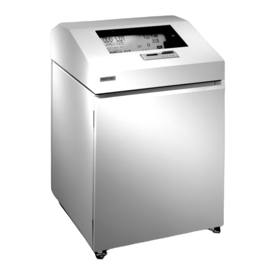
Controls and Indicators The locations of the printer cover, cabinet doors, and operator control panel are shown in Figure 1–1. Electrical controls and indicators are described on page 1–6. Mechanical controls and indicators are described on page 1–8. 1–4 Maintenance Overview... - Page 13 Printer Cover Lift to open Operator Control Panel Rear Door See Detail (Not shown) Hinged on right. Magnetic latch. Open by pulling left. Floor Cabinet Front Door Hinged on left. Magnetic latch. Open by pulling right edge. Operator Control Panel CLEAR PREV NEXT...
- Page 14 Electrical Controls and Indicators (Figure 1–2) Switch or Function Indicator NOTE: Only the ON LINE switch operates when the printer is on–line. All other switches operate only in the off–line state. = On O = Off Turns printer on and off. Switch is also a circuit breaker.
-
Page 15: Electrical Controls And Indicators
(On) (Off) Power Switch Message Display Status Lamps CLEAR PREV NEXT SET TOF ON LINE VIEW ENTER DOWN RAISE PRINTER COVER TO ACCESS THESE SWITCHES Figure 1–2. Electrical Controls and Indicators Maintenance Overview 1–7... - Page 16 Mechanical Controls and Indicators (Figure 1–3) Control or Indicator Function (See Figure 1–3) Forms thickness Sets platen for paper and forms of different thick- lever nesses. Must be fully opened (raised) to load paper. Forms thickness Indicates relative thickness of forms or paper. Set the forms thickness lever at A for thin (single–part) forms, pointer and scale B for thicker forms, and so on.
-
Page 17: Mechanical Controls And Indicators
Left Tractor Door Right Tractor Door Horizontal Tractor Adjustment Lock Vertical Knob Position Knob Tractor Lock Forms Thickness Lever and Scale Forms Thickness Pointer Figure 1–3. Mechanical Controls and Indicators Maintenance Overview 1–9... -
Page 18: Tools, Test Equipment, And Supplies
Tools, Test Equipment, and Supplies The tools and equipment required for field level maintenance of P4280 printers are listed below. Item Part No. Alcohol, anhydrous (must contain no water) – RTV silicone sealant 101537–001 Adjustable wrench – Diagonal cutters –... -
Page 19: Scheduled Maintenance
Scheduled Maintenance Chapter Contents Preventive Maintenance Checks and Services (PMCS) ....2–2 Inspecting the Printer ..........2–3 Cleaning the Printer . -
Page 20: Preventive Maintenance Checks And Services (Pmcs)
Preventive Maintenance Checks and Services (PMCS) Perform preventive maintenance checks and services (PMCS) every six months or after every 1000 hours of operation, whichever comes first. Do these checks more often if the printer is used for heavy–duty, continuous printing or is located in a dusty area. PMCS are listed in Table 2–1. -
Page 21: Inspecting The Printer
Inspecting the Printer Correct any condition found during inspection that could affect printer performance or reliability. Table 2–2. Printer Inspection Items to Inspect What to Look For Check for damage, cracks, breaks, dents, gouges, Cabinet, base, scratches, frame delamination, warping, corrosion, and proper finish. Inspect fasteners for thread damage, corrosion. -
Page 22: Cleaning The Printer
Cleaning the Printer CAUTION Do not use abrasive cleaners, particularly on the window. Do not drip water into the printer. Damage to the equipment will result. When using spray solutions, do not spray directly onto the printer; spray the cloth, then apply the dampened cloth to the printer. - Page 23 11. Wipe the lower cabinet interior with a clean, lint–free cloth dampened with water and mild detergent or window cleaning solution. 12. Dry the cabinet interior with a clean, lint–free cloth. 13. Clean the shuttle assembly (page 2–6). Ribbon Spool Ribbon Spool Splined...
- Page 24 Cleaning the Shuttle Frame Assembly (Figure 2–2) Remove the shuttle cover assembly (page 5–24). Remove the shuttle frame assembly (page 5–72). Remove the paper ironer (page 5–44). WARNING Over time, the upper edge of the paper ironer can become sharp. To avoid cutting yourself, handle the paper ironer on the sides.
- Page 25 Hammer Tip Thin plate Thick plate Hammer Bank Cover Assembly Alignment Pin (2) (Not shown) Figure 2–2. Cleaning the Shuttle Frame Assembly Scheduled Maintenance 2–7...
- Page 26 Cleaning the Card Cage Fan Assembly (Figure 2–3) Open the printer cover. Remove the paper guide assembly (page 5–42). Vacuum the card cage fan assembly and surrounding areas to remove paper particles, dust, and lint. Install the paper guide assembly (page 5–42). Close the printer cover.
-
Page 27: Troubleshooting
Troubleshooting Chapter Contents Introduction ........... . . 3–2 Fault Messages . -
Page 28: Introduction
Introduction This chapter contains procedures for troubleshooting printer malfunctions. Diagnostic test procedures are covered in this chapter, but basic printer operation is not covered. Since you must operate the printer to check its performance, have the Operator‘s Guide at the printer site. Fault Messages This section lists the fault messages that can appear on the control panel display. - Page 29 Instruction Indication Step 5. — — Disconnect cable assembly W1, CCB/Mech Driver, from connector J2 on the CCB and connector J6 on the Mech Driver board. Card cage fan comes on. Replace the Reattach cable Power up the printer. common controller assembly W1, PCBA (page CCB/Mech Driver,...
-
Page 30: Dynamic Ram Fault
Dynamic RAM Fault * Instruction Indication “Dynamic RAM Fault * ” Step 2. Return printer to Set power switch to O (off). message. normal operation. Wait 15 seconds. Set power switch to 1 (on). “Dynamic RAM Fault * ” Step 3. Return printer to Disconnect the input data line message. -
Page 31: Ham. Bank Hot
Ham. Bank Hot * Instruction Indication “Ham. Bank Hot * ” message. Step 2. Return printer to Set power switch to O (off). normal operation. Wait 15 seconds. Set power switch to 1 (on). “Ham. Bank Hot * ” message. Step 3. -
Page 32: Ham. Coil Open
Ham. Coil Open * Instruction Indication “Ham. Coil Open * ” message. Step 2. Return printer to Set power switch to O (off). normal operation. Wait 15 seconds. Set power switch to 1 (on). “Ham. Coil Open * ” message. Step 3. -
Page 33: Ham. Coil Short
Ham. Coil Short * Instruction Indication “Ham. Coil Short * ” message. Step 2. Return printer to Set power switch to O (off). normal operation. Wait 15 seconds. Set power switch to 1 (on). “Ham. Coil Short * ” message. Step 3. -
Page 34: Ham. Drv. Short
Ham. Drv. Short * Instruction Indication “Ham. Drv. Short * ” message. Step 2. Return printer to Set power switch to O (off). normal operation. Wait 15 seconds. Set power switch to 1 (on). “Ham. Drv. Short * ” message. Step 3. -
Page 35: Mech Driver Hot
Mech Driver Hot * Instruction Indication “Mech Driver Hot * ” message. Step 2. Return printer to Set power switch to O (off). normal operation. Wait 15 seconds. Set power switch to 1 (on). “Mech Driver Hot * ” message. Step 3. -
Page 36: Mech Driver Link
Mech Driver Link * Instruction Indication “Mech Driver Link * ” message. Step 2. Return printer to Set power switch to O (off). normal operation. Wait 15 seconds. Set power switch to 1 (on). “Mech Driver Link * ” message. Step 3. -
Page 37: Paper Jam
Paper Jam Instruction Indication Paper path is clear. Step 2. Remove paper Inspect paper path for and go to step 2. bunched, torn, folded paper or labels. Debris found. Gently remove Step 3. Inspect the narrow paper or lint passageway between the particles with a face of the platen and the wooden stick or... -
Page 38: Paper Out
Paper Out Instruction Indication Step 2. — — Load paper. “Paper Out” message. Replace paper Return printer to Run a diagnostic self–test detector switch normal operation. (page 3–27). assembly (page 5–82). Go to step “Paper Out” message. Replace the Return printer to Run a diagnostic self–test intermediate cable normal operation. -
Page 39: Platen Open
Platen Open Instruction Indication Step 2. — — Load paper. Step 3. — — Close forms thickness lever. “Platen Open” message. Replace platen Return printer to Run a diagnostic self–test interlock switch normal operation. (page 3–27). assembly (page 5–84). Troubleshooting 3–13... -
Page 40: Ribbon Stall
Ribbon Stall Instruction Indication Forms thickness lever is set Step 2. Readjust the Check that forms thickness correctly. setting of the lever is not closed too tightly; forms thickness this can jam the ribbon and lever. Go to step shuttle. “Ribbon Stall”... -
Page 41: Shttl Cover Open
Shttl Cover Open Instruction Indication Shuttle cover damaged. Replace the Step 2. Inspect shuttle cover for shuttle cover warping, damage, or missing assembly (page magnet. (The magnet covers 5–24). the sensor housing when the cover is installed.) Shuttle cover installed correctly. Step 3. -
Page 42: Shuttle Jam
Shuttle Jam Instruction Indication Forms thickness lever set Step 2. Set forms Check the forms thickness correctly. thickness lever for lever: if it is set too tightly, it thicker paper. Go can slow the shuttle enough to step 2. to trigger the fault message. “Shuttle Jam”... -
Page 43: Software Error
Software Error * Instruction Indication “Software Error * ” message. Step 2. Return printer to Set power switch to O (off). normal operation. Wait 15 seconds. Set power switch to 1 (on). “Software Error * ” message. Step 3. Problem is not in Disconnect the input data line the printer. -
Page 44: Symptoms Not Indicated By Fault Messages
Symptoms Not Indicated by Fault Messages Troubleshoot malfunctions not indicated by fault messages using standard fault–isolation techniques: Debrief the operator for a general description of the problem. Verify the fault by running diagnostic self–tests or replicating conditions reported by the user. Locate the malfunction using the half–split method: a. -
Page 45: Troubleshooting Aids
Troubleshooting Aids • Printer Confidence Check (page 3–20). This procedure systematically checks basic printer operations and functions. Use it to establish basic printer status or for troubleshooting imprecise or intermittent symptoms. • Diagnostic Check of Microprocessors (page 3–21). This procedure checks processor operations on the printed circuit board assemblies (PCBAs). -
Page 46: Printer Confidence Check
Printer Confidence Check Instruction Indication Power cable installed correctly Step 2. Connect printer to Check that printer is plugged to proper source. correct power into correct power source. source. (Ref.: User’s Manual) Printer operates correctly. Fault is not in the Step 3 Disconnect the interface printer. -
Page 47: Diagnostic Check Of Micorprocessors
Diagnostic Check of Microprocessors This procedure checks the operation of the microprocessors and IC chips on the Common Controller (CCB) and Mechanism Driver boards. Do the steps in the order presented. Set the power switch to O (off). Remove the paper guide assembly (page 5–42). Reseat the CCB and Mech Driver boards in the card cage. - Page 48 means RAM and ROM for the 68010 are okay, but the 64180 is not executing instructions. Go to step 7. d. If the 68010 LED blinks steadily at 1 blink per second, it means that the 68010 ROMs are bad. Turn off the printer, remove the CCB (page 5–46), and check that all ROM chips are inserted in the correct position and with all pins inserted correctly.
- Page 49 The 68010 LED turns on, then off, but the printer doesn’t work. Look at the control panel display: a. If the display is blank, or has a single line of black squares across the top, the connector to the control panel probably needs to be plugged in or reseated.
- Page 50 XON/XOFF if possible; this requires the least complex cable. d. If the printer prints from the host, but occasionally loses blocks of data, the most likely cause is the host not responding to “send no more data” signals from the printer. With a Centronics interface, this means the host is ignoring BUSY;...
- Page 51 If the printer prints garbled data or slews uncontrollably, put the printer into hex dump mode and analyze the binary data. One cause of garble is the host interface or cable is not transmitting all the data. When this occurs, the Centronics or Dataproducts interface receives a 1 on every unconnected data line.
- Page 52 e. If the failure persists, replace the common controller board (CCB). The 68010 LED lights, but never turns off. Look at the control panel display: a. If the top line of the display is blank, the control panel is probably unplugged or defective. Do the corrective actions listed in step 5.a.
-
Page 53: Diagnostic Self-Tests
Diagnostic Self–Tests Run diagnostic self–tests to check the print quality and operation of the printer. The self–tests are listed below. NOTE: Under the description of each diagnostic test is a list of items that may require field replacement or adjustment if the test produces a bad print pattern. - Page 54 Ribbon Hammer bank cover MPU sensor Hammer spring Hammer coil (shuttle frame assembly) • All Underlines An underline pattern useful for identifying hammer bank misalignment. Mechanism Driver PCBA Hammer bank cover Hammer tips Paper feed belt or motor Splined shaft bearings Tractor bearings or belts •...
-
Page 55: Running The Diagnostic Self-Tests
Running the Diagnostic Self–Tests To run a diagnostic self–test: On the control panel, press the ON LINE switch to place the printer off–line. “Off–line Ready” displays. Raise the printer cover. On the control panel, press the UP and DOWN switches simultaneously. -
Page 56: Hex Code Printout
Hex Code Printout Hex dumps list all ASCII character data received from the host computer with their corresponding two–digit hexadecimal codes. (The ASCII character set is on page 3–31.) You can use hex dumps to troubleshoot printer data reception problems. Printable characters print as the assigned symbol;... -
Page 57: Ascii Character Set
ASCII Character Set BITS OCTAL equivalent DECIMAL equivalent HEX equivalent ASCII Character BITS COLUMN (XON) ” 0 0 1 0 0 0 1 1 (XOFF) 0 1 0 0 0 1 0 1 & 0 1 1 0 ’ 0 1 1 1 1 0 0 1 1 0 1 0 1 0 1 1... -
Page 58: Hidden Diagnostics Menu
Hidden Diagnostics Menu The Hidden Diagnostics Menu consists of operational checks and calibrations made at the operator control panel. These checks are for the use of authorized factory and field service personnel only. Accessing the Hidden Diagnostics Menu To access this menu, the printer must be on and loaded with paper. Follow these steps: Press on LINE to place the printer off–line. - Page 59 time of the error. This log can be used as an aid in verifying and troubleshooting intermittent malfunctions. Clear NVM This option clears all saved configuration values in the nonvolatile memory. These values include the saved configuration under all emulations, the print statistics, the error log, and the phasing index. The printer must be recalibrated and rephased after running this option.
- Page 60 3–34 Troubleshooting...
-
Page 61: Adjustment Procedures
Adjustment Procedures Chapter Contents Preparing the Printer for Maintenance ....... . . 4–2 Belt, Paper Feed Timing, Adjustment . -
Page 62: Preparing The Printer For Maintenance
Preparing the Printer for Maintenance WARNING Unless otherwise directed, do adjustment procedures with the printer disconnected from the power source. Failure to remove power could result in injury to personnel or damage to equipment. The procedures in this chapter are written assuming the printer has been prepared for maintenance. - Page 63 Direction of Force 1. Timing Belt Shield 2. Motor Mount Bolt (2) 3. Paper Feed Drive Motor Figure 4–1 . Paper Feed Timing Belt Adjustment Adjustment Procedures 4–3...
-
Page 64: Belt, Platen Open, Adjustment
Belt, Platen Open, Adjustment (Figure 4–2 ) Prepare the printer for maintenance (page 4–2). Open the printer cover. Remove the platen open belt cover (1) by squeezing the top and bottom to release the plastic tabs from the slots in the side plate. Loosen the motor mount screws (2). - Page 65 1. Belt Cover 2. Motor Mount Screw 3. Platen Open Motor Shaft Direction of Force Figure 4–2 . Platen Open Belt Adjustment Adjustment Procedures 4–5...
-
Page 66: Hammer Phasing
Hammer Phasing Adjustment (Figure 4–3 ) NOTE: Hammer phasing must be checked and adjusted when PROMs on the common controller PCBA are replaced. Phasing adjustments should be made with the printer printing at full paper width. Load full width (132 column) paper and ribbon. Connect the power cord to the AC power source. - Page 67 NEEDS CORRECT NEEDS ADJUSTMENT ADJUSTMENT Figure 4–3 . Hammer Phasing Adjustment Adjustment Procedures 4–7...
-
Page 68: Paper Drive Motor Pulley Alignment
Paper Drive Motor Pulley Alignment (Figure 4–4 ) Prepare the printer for maintenance (page 4–2). Open the printer cover. Remove the timing belt cover (1) by squeezing the top and bottom to release the plastic tabs from the slots in the side plate. Loosen the set screw (2) in the motor pulley collar (3). - Page 69 1. Belt Shield 2. Set Screw 3. Motor Pulley Collar 4. Motor Pulley 5. Splined Shaft Pulley Figure 4–4 . Paper Drive Motor Pulley Alignment Adjustment Procedures 4–9...
-
Page 70: Paper Scale Alignment
Paper Scale Alignment (Figure 4–5 ) Load paper and ribbon. Connect the power cord to the ac power source. Set the printer power switch to 1 (on). Open the printer cover. Verify that the shuttle cover (1) is properly installed (page 5–24). Print a full 132 column line by selecting and running one of the diagnostic self–tests. - Page 71 1. Shuttle Cover 2. Screw, Button–Head, 5/64 inch hex (3) 3. Paper Scale Figure 4–5 . Paper Scale Alignment Adjustment Procedures 4–11...
-
Page 72: Platen Angle Adjustment
Platen Angle Adjustment (Figure 4–6 ) Prepare the printer for maintenance (page 4–2). Remove the shuttle cover (page 5–24). Close the forms thickness lever (1) all the way. Install the platen angle adjustment tool (P/N 996146–001) (2) and check the angle of the platen (3). a. - Page 73 1. Forms Thickness Lever 2. Platen Angle Adjustment Tool (P/N 996146–001) 3. Platen 4. Clamp Screw 5. Setscrew Figure 4–6 . Platen Angle Adjustment Adjustment Procedures 4–13...
-
Page 74: Platen Gap Adjustment
Platen Gap Adjustment (Figure 4–7 ) Prepare the printer for maintenance (page 4–2). Open the printer cover. Remove the shuttle cover assembly (page 5–24). Remove the ribbon. Loosen the platen open belt (page 4–4, steps 3. and 4.). Raise the forms thickness lever (1) to the fully open position. CAUTION Do not force the platen against the feeler gauge. -
Page 75: Platen Gap Adjustment
1. Forms Thickness Lever 2. Feeler Gauge (0.010 inch) 3. Hammer Bank Cover Plate 4. Ribbon Mask 5. Set Screw, 3/32 inch hex (2) 3/32 inch hex NOTE: Left side adjustment shown. Right side is the same. Figure 4–7 . Platen Gap Adjustment Adjustment Procedures 4–15... - Page 76 Platen Open Motor Pulley Alignment (Figure 4–8 ) Prepare the printer for maintenance (page 4–2). Open the printer cover. Remove the platen open belt cover (1) by squeezing the top and bottom to release the plastic tabs from the slots in the side plate. Loosen the set screw (2) in the motor pulley.
-
Page 77: Platen Open Motor Pulley Alignment
1. Belt Cover 2. Set Screw 3. Platen Open Motor Pulley 4. Platen Shaft Pulley Figure 4–8 . Platen Open Motor Pulley Alignment Adjustment Procedures 4–17... -
Page 78: Ribbon Guide Alignment
Ribbon Guide Alignment (Figure 4–9 ) Open the printer cover. Load paper and install the ribbon. To adjust the left ribbon guide, the ribbon should have a full spool on the right hub (1). Run a shuttle and ribbon diagnostic self–test (page 3–27). To adjust the left ribbon guide, momentarily short between the left ribbon guide skid screws (2) to assure right to left motion of the ribbon. - Page 79 1. Right Hub 2. Screw, Left Ribbon Guide Skid (2) 3. Ribbon 4. Ribbon Guide, Left 5. Screw, Retaining (2) 6. Left Spool 7. Ribbon Guide, Right Figure 4–9 . Ribbon Guide Alignment Adjustment Procedures 4–19...
-
Page 80: Splined Shaft Skew Adjustment
Splined Shaft Skew Adjustment (Figure 4–10 ) If lines of print are not parallel with the edge perforations on the paper, perform the following adjustment. Prepare the printer for maintenance (page 4–2). Loosen the screw (1) securing the adjusting link (2). Adjust the link (2) by raising or lowering the horizontal adjustment knob (5) to obtain print parallel with paper perforations. -
Page 81: Splined Shaft Skew Adjustment
1. Screw 2. Adjusting Link 3. Horizontal Adjustment Knob Figure 4–10 . Splined Shaft Skew Adjustment Adjustment Procedures 4–21... -
Page 82: Returning The Printer To Normal Operation
Returning the Printer to Normal Operation Load paper. Install the ribbon. Close floor cabinet doors and the printer cover. Connect the ac power cord to the power source and the printer. Set the power switch to 1 (on). Test printer operation by selecting and running one of the diagnostic self–tests (page 3–27). -
Page 83: Replacement Procedures
Replacement Procedures Chapter Contents Replacement Procedures ......... . . 5–3 Preparing the Printer for Maintenance . - Page 84 PROMs and Chips on the Mechanism Driver ..... . . 5–60 Resistors, Terminating ......... 5–62 Ribbon Hub .
-
Page 85: Preparing The Printer For Maintenance
Replacement Procedures CAUTION The components specified in this chapter are replaced in the field, but must be repaired at the factory. Do not attempt field repair of these items. This chapter contains illustrated removal/installation procedures for components replaceable at the field service level of maintenance. The removal/installation tasks are listed on pages 5–1 and 5–2. -
Page 86: Belt, Paper Feed Timing
Belt, Paper Feed Timing (Figure 5–1 ) Removal Prepare the printer for maintenance (page 5–3). Open the printer cover. Remove the paper guide assembly (page 5–42). Remove four screws and the barrier shield. (See Figure 5–35 , page 5–83.) Remove the timing belt cover (1) by squeezing the top and bottom to release the plastic tabs from the slots in the side plate. - Page 87 Direction of Force 1. Timing Belt Cover (P/N 150793–001) 2. Screw (2) (Scr, Hex, w/LW 10–32x.50) 3. Paper Feed Timing Belt (P/N 108664–003) 4. Motor Pulley ( p/o item 6.) 5. Splined Shaft Pulley (P/N 150289–001; p/o item 7.) 6. Paper Feed Drive Motor (P/N 150452–001) (Paper Feed Drive Motor Assembly, P/N 155005–001) 7.
-
Page 88: Belt, Platen Open
Belt, Platen Open (Figure 5–2 ) Removal Prepare the printer for maintenance (page 5–3). Open the printer cover. Remove the platen open belt cover (1) by squeezing the top and bottom to release the plastic tabs from the slots in the side plate. Loosen (do not remove) the two motor mount screws (2). - Page 89 1. Belt Cover (P/N 150769–001) 2. Screw (2) (Scr, Hex w/LW, 10–32x.50) 3. Platen Open Belt (P/N 105808–003) 4. Motor Pulley (P/N 155071–001) 5. Platen Pulley (P/N 150703–001) 6. Set Screw (Scr, Skt cap, 6–32x.44) Direction of Force Figure 5–2 . Belt, Platen Open, Removal/Installation Replacement Procedures 5–7...
-
Page 90: Cable Assembly W4, Hammer Bank
Cable Assembly (W4), Hammer Bank (Figure 5–3 ) Removal NOTE: This procedure removes the left hammer bank cable assembly. The procedure for removing the right cable assembly is the same. Prepare the printer for maintenance (page 5–3). Open the printer cover. Remove the shuttle cover assembly (page 5–24). - Page 91 Printer viewed from above, PCBAs removed. Left hammer bank Right hammer bank cable assembly cable assembly Card cage floor Card Cage Paper feed Platen motor open motor Paper feed mechanisms and barrier panel Platen Tie wraps Shuttle Frame Assembly Base casting Hammer Bank NOTE: Connector locating key is on the right side of each...
-
Page 92: Cable Assembly W5, Intermediate
Cable Assembly W5, Intermediate (Figure 5–4 ) Removal Prepare the printer for maintenance (page 5–3). Open the printer cover. Remove the paper guide assembly (page 5–42). Remove the common controller PCBA (page 5–46). Remove the mechanism driver PCBA (page 5–48). Remove screws (1) securing the intermediate cable assembly connector P1 (2) to the bottom of the card cage. - Page 93 Printer viewed from above, PCBAs removed. Ground Lug Pin 1 Card cage floor (PCBAs removed) Card Cage Paper feed Platen motor open motor Paper feed mechanisms and barrier panel Platen Shuttle Frame Assembly Paper detector switch assembly Base casting Hammer Bank 1.
- Page 94 Installation Feed the intermediate cable assembly (10) through the card cage opening and install tie wraps and cable restraints. Connect connectors CO+ and CO– (8 and 9) and install the cover open switch assembly (7). (See page 5–80.) Connect connector PMD (5) to paper detector switch assembly connector PMD(P) (6).
- Page 95 Printer viewed from above, PCBAs removed. Ground Lug Pin 1 Card cage floor (PCBAs removed) Card Cage Paper feed Platen motor open motor Paper feed mechanisms and barrier panel Platen Shuttle Frame Assembly Paper detector switch assembly Base casting Hammer Bank 1.
-
Page 96: Cable Assembly, Multi I/O
Cable Assembly, Multi I/O (Figure 5–5 ) Removal Prepare the printer for maintenance (page 5–3). Open the printer cover. Remove the paper guide assembly (page 5–42). Open the cabinet doors. Remove the paper fence through the front door. a. Cut the tie wrap and lift the top left side of the fence. b. - Page 97 1. Screw (6) (Scr, Hex, Wshr, SEMS 10–24x.50) 2. Service Panel (P/N 150538–004) 3. Ribbon Cable Restraints (P/N 107953–002 or 109822–002) 4. Latch (2) (Ref) 5. Ribbon Cable Connector (p/o item 9.) 6. Common Controller Connector J1 (Ref) 7. Screw (4) (Scr, Hex w/LW, 10–24x.38) 8.
- Page 98 Installation Feed the multi I/O ribbon cable (9) from the lower cabinet up into the opening at the right rear of the card cage. Route the ribbon cable against the right rear wall of the cabinet. Install four screws (7) securing the multi I/O cable assembly mounting plate (8).
- Page 99 1. Screw (6) (Scr, Hex, Wshr, SEMS 10–24x.50) 2. Service Panel (P/N 150538–004) 3. Ribbon Cable Restraints (P/N 107953–002 or 109822–002) 4. Latch (2) (Ref) 5. Ribbon Cable Connector (p/o item 9.) 6. Common Controller Connector J1 (Ref) 7. Screw (4) (Scr, Hex w/LW, 10–24x.38) 8.
-
Page 100: Circuit Breaker
Circuit Breaker (Figure 5–6 ) Removal Prepare the printer for maintenance (page 5–3). Open both cabinet doors. Remove the paper fence through the front door. a. Cut the tie wrap and lift the top left side of the fence. b. Lift the fence out of the hole at the bottom center. c. - Page 101 BROWN 1. Screw (6) (Scr, Hex, Wshr, SEMS 10–24x.50) 2. Service Panel (P/N 150538–004) 3. Circuit Breaker Electrical Lead (4) (Ref) 4. Spring Clip (4) (p/o item 5.) BLUE 5. Circuit Breaker (P/N 141286–001) BROWN BLUE Figure 5–6 . Circuit Breaker Removal/Installation Replacement Procedures 5–19...
-
Page 102: Control Panel Assembly
Control Panel Assembly (Figure 5–7 ) Removal Prepare the printer for maintenance (page 5–3). Open the printer cover. Remove the paper guide assembly (page 5–42). Open the connector latches and disconnect the control panel ribbon connector P1 (1) from connector J3 on the common controller PCBA (2). - Page 103 11. Insert the control panel ribbon cable into the wire saddles (3) on the mechanism base pan. 12. Install the paper guide assembly (page 5–42). 13. Return the printer to normal operation (page 5–86). Install block–type ferrite core here and wind cable around round core after routing cable through...
-
Page 104: Cover Assembly, Hammer Bank
Cover Assembly, Hammer Bank (Figure 5–8 ) Removal Prepare the printer for maintenance (page 5–3). Remove the shuttle frame assembly (page 5–72). Lift the thick plate of the hammer bank cover assembly (1) at one end, and peel the cover away from hammer bank magnets. Installation CAUTION The hammer bank contains a strong magnet. - Page 105 Thin plate Thick plate Alignment Pin Hole (Not shown) 1. Hammer Bank Cover Assembly (P/N 150207–001) 2. Hammer Bank (p/o 150181–901, Shuttle Frame Assy.) 3. Alignment Pin (2) (p/o 150181–901, Shuttle Frame Assy.) Figure 5–8 . Cover Assembly, Hammer Bank, Removal/Installation Replacement Procedures 5–23...
-
Page 106: Cover Assembly, Shuttle
Cover Assembly, Shuttle (Figure 5–9 ) Removal Prepare the printer for maintenance (page 5–3). Open the printer cover. Remove the ribbon spools. Loosen the shuttle cover screws (1). Grasping the edges of the shuttle cover assembly (2), tilt up the rear edge and lift the shuttle cover assembly out of the printer. - Page 107 1. Screw, Captive, Shuttle Cover (2) (Scr, 10–24x.62; O–Ring, 0.125x0.250x0.06) 2. Shuttle Cover Assembly (P/N 150808–001) Figure 5–9 . Cover Assembly, Shuttle, Removal/Installation Replacement Procedures 5–25...
-
Page 108: Fan Assembly, Card Cage
Fan Assembly, Card Cage (Figure 5–10 ) Removal Prepare the printer for maintenance (page 5–3). Open the printer cover. Remove the paper guide assembly (page 5–42). Remove two screws (1). Disconnect the fan cable connector (2). Remove the card cage fan assembly (3) and fan guard (4) from the card cage (5). - Page 109 Air Flow 1. Screw (4) (Scr, w/LW, 6–32x2.00) 2. Fan Cable Connector (p/o item 3.) 3. Card Cage Fan Assembly (P/N 150261–001) 4. Fan Guard (P/N 130025–001) 5. Card Cage (p/o Frame, Base, P/N 150803–001) Figure 5–10 . Fan Assembly, Card Cage, Removal/Installation Replacement Procedures 5–27...
-
Page 110: Fan Assembly, Cabinet Exhaust
Fan Assembly, Cabinet Exhaust (Figure 5–11 ) Removal Prepare the printer for maintenance (page 5–3). Open the floor cabinet doors. Remove the paper fence through the front door. a. Cut the tie wrap and lift the top left side of the fence. b. - Page 111 1. Screw (6) (Scr, Hex, wshr, SEMS, 10–24x.50) 2. Service Panel (P/N 150538–004) 3. Screw (4) (Scr, w/LW, 6–32x2.00) 4. Cabinet Exhaust Fan Assembly (P/N 150261–001) 5. Fan Cable Connector (p/o item 4.) 6. Fan Guard (P/N 130025–001) Air Flow Figure 5–11 .
-
Page 112: Fan Assembly, Hammer Bank
Fan Assembly, Hammer Bank (Figure 5–12 ) Removal Prepare the printer for maintenance (page 5–3). Remove the shuttle cover assembly (page 5–24). Remove two screws (1). Remove the access cover plate beneath the cabinet base pan. Reach under the base casting (2) and disconnect the hammer bank fan cable connector (3). - Page 113 Air Flow Attach cable connector here. NOTE: Do not install screw here. Route cable under base casting. Hammer Bank Front NOTE: Do not install 1. Screw (2) (Scr, Hex w/LW, 6–32x1.25) screw here. 2. Base Casting (P/N 150727–001) 3. Fan Cable Connector (p/o item 4.) 4.
-
Page 114: Hammer Spring Assembly
Hammer Spring Assembly (Figure 5–13 ) Removal Prepare the printer for maintenance (page 5–3). Remove the shuttle frame assembly (page 5–72). Remove the hammer bank cover assembly (page 5–22). Remove three 5/64 inch socket head screws from the old hammer fret. Using the pointed end of the nylon stick supplied in the hammer spring replacement kit, carefully pry the old hammer fret off its mounting pins as shown in Figure 5–13 . -
Page 115: Hammer Bank
Preparation – Frets 1 and 7 only NOTE: Right end If you replace fret 1 or 7, bend the end hammer down BEFORE removing it from the box, as shown below. Do this ONLY Hammer Bank for frets 1 and 7. Bend this hammer if Left end Bend this hammer if... -
Page 116: Magnetic Pick–Up (Mpu) Assembly
Magnetic Pick–up (MPU) Assembly (Figure 5–14 ) Removal Prepare the printer for maintenance (page 5–3). Remove the shuttle cover (page 5–24). Disconnect the magnetic pick–up (MPU) cable connector (1). Loosen the 7/64 inch hex MPU clamp screw (2). Remove the MPU assembly (3) by unscrewing it from the MPU bracket (4). - Page 117 ± 0.010 .001INCH NOTE: For clarity in showing this assembly, the extension spring is not shown. Attach MPU cable here. CAUTION: Make sure the MPU cable does not touch extension spring (P/N 106710–006) after cable connection. 1. MPU Cable Connector (p/o) item 3.) 2.
-
Page 118: Motor Assembly, Ribbon Drive
Motor Assembly, Ribbon Drive (Figure 5–15 ) Removal NOTE: The procedure below is the same for the left and right ribbon drive motor assemblies. Prepare the printer for maintenance (page 5–3). Remove the ribbon. Remove the ribbon hub (page 5–64). Remove two screws (1) and washers (2). - Page 119 Install block–type ferrite core here. Refer to Appendix F. 1. Screw (2) (Scr, Hex w/LW, 6–32x.50) 2. Washer (2) (Flat #6) 3. Ribbon Drive Motor (P/N 150452–001) 4. Base Casting (P/N 150727–001) 5. Ribbon Motor Cable Connector (p/o item 3.) Figure 5–15 .
-
Page 120: Motor Assembly, Paper Feed
Motor Assembly, Paper Feed (Figure 5–16 ) Removal Prepare the printer for maintenance (page 5–3). Open the printer cover. Remove the paper guide assembly (page 5–42). Remove four screws and the barrier shield. (See Figure 5–35 .) Remove the timing belt cover (1) by squeezing the top and bottom to release the plastic tabs from the slots in the side plate. - Page 121 10. Install the paper guide assembly (page 5–42). 11. Return the printer to normal operation (page 5–86). Direction of Force 1. Belt Cover (P/N 150793–001) 2. Set Screw (6–32x.51) 3. Paper Feed Motor Pulley (P/N 108627–001) 4. Collar (P/N 140763–002) 5.
-
Page 122: Motor Assembly, Platen Open
Motor Assembly, Platen Open (Figure 5–17 ) Removal Prepare the printer for maintenance (page 5–3). Remove the card cage fan assembly (page 5–26). Remove the platen open belt cover (1) by squeezing the top and bottom to release the plastic tabs from the slots in the side plate. Loosen the motor mount screws (2). - Page 123 Direction of Force 1. Cover, Platen Open Belt (P/N 150769–001) 2. Screw (2) (Hex, w/LW, 10–32x.50) 3. Platen Open Belt (P/N 105808–003) 4. Set Screw, Collar (Scr, set, locking, 6–32x.25) 5. Motor Pulley (P/N 155071–001) 6. Platen Motor Cable Connector (p/o item 8.) 7.
-
Page 124: Paper Guide Assembly
Paper Guide Assembly (Figure 5–18 ) Removal Prepare the printer for maintenance (page 5–3). Open the printer cover. Remove the hold–down screw (1). Slightly lift the right end and slide the paper guide assembly (2) to the left. Lift the paper guide assembly off the card cage (3). Installation Position the paper guide assembly (2) offset slightly to the left on the card cage (3). - Page 125 Clips on card cage top. (Not shown.) NOTE: Remove screw and lift this end before sliding the cover. Engage clips here. 1. Hold–Down Screw (Hex, w/LW, 6–32x.25, and Washer, flat, #6) 2. Paper Guide Assembly (Ref) 3. Card Cage (p/o frame, base, P/N 150803–001) Figure 5–18 .
-
Page 126: Paper Ironer
Paper Ironer (Figure 5–19 ) Removal Remove the shuttle frame assembly (page 5–72). Move the forms thickness lever (1) to the open position. WARNING Over time, the upper edge of the paper ironer can become sharp. To avoid cutting yourself, grasp the paper ironer on the sides. Push back at the ends of the paper ironer (2) to disengage the tabs, then lift it up and out. - Page 127 NOTE: Black label on back side of newer models. Push and Lift Push and Lift 1. Forms Thickness Lever (P/N 111724–001) 2. Paper Ironer (P/N 150434–001) Figure 5–19 . Paper Ironer Removal/Installation Replacement Procedures 5–45...
-
Page 128: Pcba, Common Controller
PCBA, Common Controller (Figure 5–20 ) CAUTION To prevent electrostatic damage to electronic components, wear a properly grounded static wrist strap when handling PCBAs. Removal Make a configuration printout. (Refer to Appendix A.) Prepare the printer for maintenance (page 5–3). Open the printer cover. - Page 129 10. Return the printer to normal operation (page 5–86). 11. Using the configuration printout you made as step 1 of the removal procedure, reset and save the printer configuration. (Refer to Appendix NOTE: Power Supply and Mechanism Driver boards shown for reference. They are not removed in this procedure.
-
Page 130: Pcba, Mechanism Driver
PCBA, Mechanism Driver (Figure 5–21 ) CAUTION To prevent electrostatic damage to electronic components, wear a properly grounded static wrist strap when handling PCBAs. Do not flex the board or grasp components on the PCBA during removal/installation. Damage to components may result. Handle the board carefully by the ejections levers, sides, or the heat sink. - Page 131 NOTE: Power Supply and Common Controller boards shown for reference. They are not removed in this procedure. 1. CCB/Mech. Driver Ribbon Cable (P/N 150551–001 2. Connector J6 (p/o item 6.) 3. Power Supply Cable (P/N 150218–001) 4. Connector J7 (p/o item 6.) 5.
-
Page 132: Pcba, Power Supply
PCBA, Power Supply (Figure 5–22 ) WARNING To prevent injury from electric shock, wait at least one minute after shutting off power before removing the power supply PCBA. Do not touch components or flex the board during removal/installation. Handle the board by the ejections levers and the sides. Wear a properly grounded static wrist strap when handling the power supply PCBA. - Page 133 NOTE: Mechanism Driver and Common Controller boards shown for reference. They are not removed in this procedure. 1. Mechanism Driver Power Supply Cable (P/N 150218–001) 2. Connector J102 (p/o item 4.) 3. Ejection Lever (2) (p/o item 4.) 4. Power Supply PCBA (P/N 150316–901) 5.
-
Page 134: Platen
Platen (Figure 5–23 ) Removal Prepare the printer for maintenance (page 5–3). Remove the shuttle frame assembly (page 5–72). Remove the paper ironer (page 5–44). Remove the paper ironer bracket: a. Remove three screws (1). b. Lift the two–piece bracket (2) up and out of the printer. Remove the platen open belt (page 5–6). - Page 135 Left Side Plate 1. Screw, Hex, Thread Forming, 6–32x.250 (3) 2. Ironer Bracket Assy. (bracket: 150577–001; plate: 150650–001) 3. Screw, Set, Skt, Cap, 6–32x.44 4. Pulley, Platen Open (P/N 150703–001) 5. Spring, Platen Support (P/N 105741–001) 6. Link, Spring, Platen Support (P/N 150664–001) 7.
- Page 136 Installation IMPORTANT The dowel pins protruding from the ends of the platen are called the platen shafts, and are not equal in length. The platen must be installed with the longer shaft on the right side. Install two washers (15) on the longer platen shaft. Apply M–3 lubricant to both platen shafts and to the mating diameters of the platen adjustment brackets (16).
- Page 137 Left Side Plate 1. Screw, Hex, Thread Forming, 6–32x.250 (3) 2. Ironer Bracket Assy. (bracket: 150577–001; plate: 150650–001) 3. Screw, Set, Skt, Cap, 6–32x.44 4. Pulley, Platen Open (P/N 150703–001) 5. Spring, Platen Support (P/N 105741–001) 6. Link, Spring, Platen Support (P/N 150664–001) 7.
- Page 138 Installation (continued) 11. Install the platen pulley so that it is aligned with the platen open motor pulley (page 4–8). 12. Install, but do not adjust, the platen open belt (page 5–6). 13. Install the paper ironer bracket (2): a. With the flat piece of the bracket facing the front of the printer, place the two hooks of the upper piece over the platen shafts.
- Page 139 Left Side Plate 1. Screw, Hex, Thread Forming, 6–32x.250 (3) 2. Ironer Bracket Assy. (bracket: 150577–001; plate: 150650–001) 3. Screw, Set, Skt, Cap, 6–32x.44 4. Pulley, Platen Open (P/N 150703–001) 5. Spring, Platen Support (P/N 105741–001) 6. Link, Spring, Platen Support (P/N 150664–001) 7.
-
Page 140: Proms And Chips On The Ccb
PROMs and Chips on the CCB (Figure 5–24 ) CAUTION To prevent electrostatic damage to electronic components, wear a properly grounded static wrist strap when handling PCBAs and components. Removal Make a configuration printout. (Refer to Appendix A.) Prepare the printer for maintenance (page 5–3). Remove the common controller PCBA (page 5–46). - Page 141 LEGEND PROM Kit: P/N 150122–901 DPMC = Dot Plucker Memory Controller DPU = Data Processing Unit FTIC = Fire Timer IC LED = Light–Emitting Diode MPU = Magnetic Pick–up NOVRAM = Nonvolatile Random Access Memory PAL = Programmable Array Logic PFC = Paper Feed Controller RTPU 68010...
- Page 142 PROMs and Chips on the Mechanism Driver (Figure 5–25 ) Removal Prepare the printer for maintenance (page 5–3). Remove the mechanism driver PCBA (page 5–48). CAUTION To prevent electrostatic damage to electronic components, wear a properly grounded static wrist strap when handling PCBAs and components.
-
Page 143: Proms And Chips On The Mechanism Driver
LEGEND RSP = Ribbon/Shuttle Processor ASIC = Application–Specific Integrated Circuit Hammer Driver ASIC RSP PROM 8032 150846 Mech. Driver ASIC Microcontroller Figure 5–25 . PROMs and Chips on the Mechanism Driver Replacement Procedures 5–61... -
Page 144: Resistors, Terminating
If the standard terminating resistor pack is not compatible with the particular interface driver requirements of the host computer, other values of pull–up and pull–down resistors may be required. Printronix provides the 220 ohm pull–up and 330 ohm pull–down alternate terminating resistors. If you install the 220 ohm pull–up resistor, you must also install the 330 ohm pull–down... - Page 145 Standard: 470 ohm DIP Alternate: 220 ohm DIP Pull–up (Location 12C) Standard: 1K ohm DIP Alternate: 330 ohm DIP Pull–down (Location 12D) Figure 5–26 . Resistors, Terminating, Removal/Installation Replacement Procedures 5–63...
-
Page 146: Ribbon Hub
Ribbon Hub (Figure 5–27 ) Removal Prepare the printer for maintenance (page 5–3). Remove the printer ribbon. Loosen the screw (1) in the ribbon spool hub (2). Remove the hub (2) from the shaft of the ribbon drive motor (3). Installation Install the ribbon spool hub (2) over the motor shaft. - Page 147 1. Hub Screw (6–19x.50) 2. Ribbon Spool Hub Kit (P/N 150868–001) 3. Ribbon Drive Motor (P/N 150452–001) Figure 5–27 . Ribbon Hub Removal/Installation Replacement Procedures 5–65...
-
Page 148: Ribbon Guide Assembly (L/R)
Ribbon Guide Assembly (L/R) (Figure 5–28 ) Removal NOTE: Although the right ribbon guide is shown in Figure 5–28 , the removal procedure is the same for the left ribbon guide. Prepare the printer for maintenance (page 5–3). Open the printer cover. Remove the printer ribbon. - Page 149 1. Tie Wrap, 5.75 inch (P/N 101480–002) 2. Ribbon Guide Connector (p/o item 5.) 3. Screw (2) (Hex, w/LW 4–40x.38) 4. Washer (2) (Flat #4) 5. Ribbon Guide Assembly, Right (P/N 150222–002) Ribbon Guide Assembly, Left (P/N 150222–001) 6. Side Plate, R (P/N 150772–001; Side Plate, L, P/N 150771–001) Figure 5–28 .
-
Page 150: Shaft, Splined
Shaft, Splined (Figure 5–29 ) Removal Prepare the printer for maintenance (page 5–3). Open the printer cover. Remove the paper feed timing belt (page 5–4). Remove the screw (1) and ground clip (2). With grip ring pliers, remove the grip ring (3) from the splined shaft (4). Pull the bearing (5) and spring link (6) with the spring (7) off the splined shaft (4). - Page 151 1. Screw, Hex w/LW (4–20x.50) 2. Ground Clip (Mfg. P/N 150784–001) 3. Grip Ring (P/N 101551–002) 4. Splined Shaft Assembly (P/N 150491–001) 5. Bearing, Nylon, .376 (P/N 101309–001) 6. Spring Link (P/N 110280–001) 7. Spring, Extension (P/N 105741–003) 8. Tractor, Left (Set, L/R, P/N 140716–003) 9.
-
Page 152: Shaft, Support
Shaft, Support (Figure 5–30 ) Removal Prepare the printer for maintenance (page 5–3). Open the printer cover. Unlock the tractors (1) and slide them to the far right. Remove the E ring (2). Slide the support shaft assembly — consisting of the support shaft (3), two curved washers (4), bushing (5), horizontal adjustment knob (6), washer (7) and screw (8) —... - Page 153 1. Tractor (2) (Set, L/R, P/N 140716–003) 2. E Ring (P/N 105678–001) 3. Support Shaft (P/N 111685–001) 4. Curved Washer (2) (P/N 101552–004) 5. Bushing (P/N 111684–001) 6. Horizontal Adjustment Knob (P/N 111822–001) 7. Washer (Flat #4) 8. Screw (Skt cap, 4–40x.25) 9.
-
Page 154: Shuttle Frame Assembly
Shuttle Frame Assembly (Figure 5–31 ) Removal Prepare the printer for maintenance (page 5–3). Remove the shuttle cover assembly (page 5–24). Disconnect the MPU cable connector (1). Disconnect the shuttle motor cable connector (2). Disconnect the shuttle cable assembly connector (3). CAUTION The hammer bank flex circuit ribbon cables can tear if handled roughly. - Page 155 Flat #10 2 Places NOTE: Center captive screw NOTE: exploded for clarity. Clamp hardware Do not remove it. exploded for clarity. Do not remove. 1. MPU Cable Connector (Ref) 2. Shuttle Motor Cable Connector (Ref) 3. Shuttle Cable Assembly Connector (Ref) 4.
- Page 156 Installation Install the hammer bank cover (page 5–22), if it was removed. Holding the shuttle frame assembly (10) by the outer beam standoffs (12), set it into the base casting (11). Use both hands: the shuttle frame assembly is heavy. Align the center 5/32 inch socket head screw (9) in the base casting (11) and hand turn the screw until only two or three threads have started.
- Page 157 Flat #10 2 Places NOTE: Center captive screw NOTE: exploded for clarity. Clamp hardware Do not remove it. exploded for clarity. Do not remove. 1. MPU Cable Connector (Ref) 2. Shuttle Motor Cable Connector (Ref) 3. Shuttle Cable Assembly Connector (Ref) 4.
-
Page 158: Spring Assembly, Gas
Spring Assembly, Gas (Figure 5–32 ) Removal Prepare the printer for maintenance (page 5–3). Open the printer cover (1). Open the floor cabinet rear door. WARNING Hold the printer cover securely while disengaging the gas spring assembly. Pry back the spring retaining clips. Remove the gas spring assembly (4) from the ball studs (7). - Page 159 1. Printer Cover (P/N 150814–001) 2. Nut (Hex, .312–18) 3. Washer (Split lock, 5/16) 4. Gas Spring Assembly (P/N 107961–005) 5. Upper Bracket (p/o item 1.) 6. Lower Bracket (Ref) 7. Ball Stud (2) (P/N 107962–001) Figure 5–32 . Spring Assembly, Gas, Removal/Installation Replacement Procedures 5–77...
-
Page 160: Spring, Extension
Spring, Extension (Figure 5–33 ) CAUTION Do not allow the hammer bank to rotate toward the platen during spring replacement. Removal Prepare the printer for maintenance (page 5–3). Open the printer cover. Remove the shuttle cover assembly (page 5–24). Unhook the extension spring (1) from the spring lugs (2) on the hammer bank (3) and shuttle frame (4). - Page 161 1. Extension Spring (P/N 106710–006) 2. Spring Lug (2) (p/o item 4.) 3. Hammer Bank (p/o item 4.) 4. Shuttle Frame (Ref) Figure 5–33 . Spring, Extension, Removal/Installation Replacement Procedures 5–79...
-
Page 162: Switch Assembly, Cover Open
Switch Assembly, Cover Open (Figure 5–34 ) Removal Prepare the printer for maintenance (page 5–3). Open the printer cover. Remove the shuttle cover assembly (page 5–24). Remove two screws (1), if present, and lift or pry the cover open switch assembly (2) out of the base casting. - Page 163 Printer viewed from above. Card Cage Card cage Paper feed Platen motor open motor Paper feed mechanisms and barrier panel Platen Shuttle Frame Assembly Base casting NOTE: Newer models use pressure–sensitive adhesive backing on the switch. This section of cable runs Discard screws if installing switch beneath the base casting.
-
Page 164: Switch Assembly, Paper Detector
Switch Assembly, Paper Detector (Figure 5–35 ) Removal Prepare the printer for maintenance (page 5–3). Remove the paper guide assembly (page 5–42). Remove four screws (1) and the barrier shield (2). Remove the screws (3) securing the paper detector switch assembly (4). Disconnect the paper detector switch cable connector (5) from the intermediate cable assembly connector PMD. - Page 165 1. Screw (4) (Thread forming, 6–32x.25) 2. Barrier Shield (P/N 150303–001) 3. Screw (2) (Thread finding, 6–32x.375) 4. Paper Detector Switch Assembly (P/N 150834–001) 5. Paper Detector Switch Cable Connector (p/o item 4.) Figure 5–35 . Switch Assembly, Paper Detector, Removal/Installation Replacement Procedures 5–83...
-
Page 166: Switch Assembly, Platen Interlock
Switch Assembly, Platen Interlock (Figure 5–36 ) Removal Prepare the printer for maintenance (page 5–3). Open the printer cover. Disconnect the platen interlock switch connector (1) from connector P1(P) (2). Fully close the forms thickness lever (3). Remove two screws (4). Remove the platen interlock switch assembly (5) from the forms thickness indicator plate (6). - Page 167 1. Platen Interlock Switch Connector (p/o item 5.) 2. Connector P1(P) (Ref) 3. Forms Thickness Lever (P/N 111724–001) 4. Screw (2) (CRCFM, 2–28x.63) 5. Platen Interlock Switch Assembly (P/N 150284–001) 6. Forms Thickness Indicator Plate (P/N 110144–001) Figure 5–36 . Switch Assembly, Platen Interlock, Removal/Installation Replacement Procedures 5–85...
-
Page 168: Tractor (L/R)
Tractor (L/R) Removal Prepare the printer for maintenance (page 5–3). Remove the splined shaft (page 5–68). Remove the support shaft (page 5–70). Remove the tractors. Installation Using the replacement tractors, install the support shaft (page 5–70). Install the splined shaft (page 5–68). Return the printer to normal operation (see below). -
Page 169: Optional Equipment
Optional Equipment Contents IGP–200/210 Option ..........6–2 CT Option . -
Page 170: Igp-200/210 Option
IGP–200/210 Option The Intelligent Graphics Processor (IGP) is a printed circuit board assembly that processes and plots all graphics, freeing the host computer for other tasks. Using a simple programming language, the user can create forms, bar codes, logos, expanded characters, and other graphics. The IGP enables the printer to print sideways, upside down, and make forms combining graphics, alphanumeric data, and bar codes, all in a single pass. - Page 171 a. Route the cable straight across the bottom of the card cage. b. Hold the cable vertical against the front edge of the card cage, remove the slack in the cable, and install two tie wraps. Make sure the part of the cable covered by the heat–shrink tubing is under the tie wraps.
- Page 172 IGP–200/210 Installation (continued) Install the power supply board: (See Figure 6–2.) a. Make sure the CT/IGP–2X0 power cable runs between the heat sinks and transformers as you slide the power supply board into position. b. Connect the CT/IGP–2X0 power cable connector to the power supply board.
- Page 173 Multi–I/O Cable (P/N 150310–002) IGP Control Panel Cable Printer Control Panel Cable Mech. Driver Power Supply Power Supply Cable P1 Interconnect Cable (P/N 155026–001) CCB/Mech. Driver Cable (P/N 150551–001) CT/IGP–2X0 Power Cable (P/N 155054–001) Figure 6–2. Installing the Circuit Boards and Cables Optional Equipment 6–5...
- Page 174 16. Stow cable slack in the wire saddles on the right side of the printer base plate. 17. Install the paper guide assembly (page 5–42). 18. Configure the printer for Dataproducts interface. (Refer to the P4280 Setup Guide.) 19. For information about IGP operation and programming, refer to the IGP User’s Manual.
- Page 175 IGP Control Panel Captive Screw (Not Shown) Captive Screw Shuttle Cover Control Panel Support Bracket IGP Ribbon Cable Connector J11 Screw (2) Hex w/LW 6x.25 IGP Control Panel Connector J11 Wire Saddle Figure 6–3. Installing the IGP Control Panel Optional Equipment 6–7...
-
Page 176: Ct Option
P4280 to emulate IBM 5225 Models 1, 2, 3, and 4 and 4234 Model 2 printers. A P4280 equipped with the CT option can be attached directly to an IBM network. A switch on the interface plate enables the CT to be set to receive data via coaxial or twinaxial lines. - Page 177 Cable Coax/twinax I/O Restraints Cable Assembly Screw (4) Service Panel Route cables into the card cage. Screw (6) NOTE: To prevent crushing, install cables at bottom of restraints. Coax/twinax I/O interface connector plate (P/N 112435–001) Figure 6–4. Installing the Coax/Twinax I/O Cable Assembly Optional Equipment 6–9...
- Page 178 CT Installation (continued) Install the CT power cable to the front and bottom of the card cage: (See Figure 6–5.) a. Lay the CT power cable in the card cage so the portion covered by heat–shrink tubing runs straight up the front wall of the card cage.
- Page 179 Tie Wrap Tie Wrap CT Power Cable (P/N 155029–001) Figure 6–5. Installing the CT Power Cable Optional Equipment 6–11...
- Page 180 CT Installation (continued) Install the PCBA guides onto the CT bracket. (See Figure 6–6.) Install the CT bracket on the rear wall of the card cage with two screws. NOTE: Notch must be at top of Screw (2) bracket. SEMS, Hex, wshr, 10–24x.375 Card Cage Fan Card Cage...
- Page 181 CT Installation (continued) On the common controller board, replace the DCU PROMs at locations H1 and H2 with the PROMs included in this kit. (See Figure 6–7.) Remove these DPU PROMs and install the Common Controller Board (CCB) ones in the CT kit. DPU –002 DPU –001 Font –002...
- Page 182 CT Installation (continued) Connect the CT interconnect cable to connector P1 on the CT board. (See Figure 6–2.) Connect the CT power cable to the power connector on the CT board. Connect the orange CT I/O cable to pins 1 and 2 of connector P2 on the CT board.
- Page 183 Connector P2 Detail Beveled edge rests on board. Note location CT Power of pin 1. Cable Orange CT See Detail (Connect as I/O Cable shown.) Grey CT I/O Cable CCB/Mech. Driver Cable CT Interconnect (P/N 150551–001) Cable Printer Control (P/N 155028–001) Panel Cable Mech.
-
Page 184: Ct Control Panels
CT Control Panels A P4280–CT printer uses either a coax or a twinax control panel. This section describes the switches and indicators on coax and twinax control panels. Coax Control Panel TEST ENTER INSPC BUFRP CANCEL CHECK ENABLE/HOLD FORM FEED... - Page 185 Optional Equipment 6–17...
- Page 186 6–18 Optional Equipment...
-
Page 187: Error Processing
Error Processing This section contains procedures for troubleshooting printer malfunctions. You must operate the printer to check printer performance after correcting problems, so have the Operator’s Guide at the printer site. Although diagnostic self–test procedures are covered in this chapter, basic printer operation is not covered. -
Page 188: Fault Messages
Fault Messages IMPORTANT Test the printer after every corrective action. Stop maintenance when the symptom disappears. Always press the ENABLE/HOLD switch after correcting a fault indicated by a fault message. If the fault message appears after pressing ENABLE/HOLD, go to the following tables, find the message, and perform the checks and corrective actions listed in the table. - Page 189 • NVRAM • INTERNAL ERROR HAMMER DRV ERROR Twinax Printers Only –– System Communication or Data Errors: • SCS Code Error • SCS Parameter Error • GRAPHIC CHECK • ACTIVATE LOST • INVALID COMMAND • INVALID ACTIVATE • INPUT QUEUE OVERRUN PARITY ERROR COOLING ERROR Instruction...
-
Page 190: Internal Error
HAMMER DRV ERROR Instruction Indication Set power switch to O HAMMER DRV Step 2. Return printer to (OFF). Wait 5 seconds. ERROR message. normal operation. Set power switch to 1 (ON). Press the HAMMER DRV Step 3. Return printer to ENABLE/HOLD switch. -
Page 191: Nvram Error
NVRAM ERROR Instruction Indication Set power switch to O NVRAM ERROR Step 2. Return printer to (OFF). Wait 5 seconds. message. normal operation. Set power switch to 1 (ON). Press the NVRAM ERROR Step 3. Return printer to ENABLE/HOLD switch. message. - Page 192 PAPER JAM Instruction Indication Inspect paper path for Paper path is clear. Step 2. Remove paper bunched, torn, folded and go to step 2. paper or labels. Inspect the narrow Debris found. Gently remove Step 3. passageway between paper or lint the face of the platen particles with a and the ribbon mask for...
- Page 193 PARITY ERROR, ACTIVATE LOST, INVALID ACTIVATE, INVLAID COMMAND or INPUT QUEUE OVER Instruction Indication Print the Error Log, Error message — which is under the CTPC displays. internal test menu (page 6–30). A few parity errors are acceptable. Check coax/twinax cable Error message Reseat cable.
-
Page 194: Ribbon Out
RIBBON FAULT Instruction Indication Check sensors. RIBBON FAULT Step 2. — message. Wind the ribbon by hand Ribbon damaged. Step 3. If folded but and check for folds, otherwise okay, tears, holes, fraying. rewind and reinstall the ribbon. Install a new ribbon. —... - Page 195 SHUTTLE STALL Instruction Indication Check forms thickness Forms thickness lever Step 2. Readjust the lever is not closed too is set correctly. setting of the tightly; this can jam the forms thickness ribbon and shuttle. lever. Go to step Run a diagnostic SHUTTLE STALL Remove the Return printer to...
-
Page 196: Symptoms Not Indicated By Fault Messages
Symptoms Not Indicated by Fault Messages NOTE: Do not attempt field repairs on electronic components or assemblies — replace the entire assembly with an operational spare. Most electronic problems are corrected by replacing the printed circuit board assembly (PCBA), sensor, or cable that causes the fault indication. - Page 197 PRINTING INCORRECT DATA Instruction Indication Power cable installed correctly Step 2. Connect printer to Verify printer is plugged into to proper source. correct power correct power source. (Refer source. to the Setup Guide.) Metallic debris. Remove debris. Step 12. Inspect for debris that could Clean printer.
-
Page 198: Printer Self Tests
Printer Self Tests The printer provides self–test information used to diagnose problems. To run the self–tests, place the printer in the PROGRAM state and run the tests as described below: Enter the Program State Press the ENABLE/HOLD switch to place the printer in the HOLD state. - Page 199 Press the switch to move through the test options. See page 6–32 for the DCU Test options and page 6–34 for the CTPC Test options. Select the test you want when the option appears on the second line of the display by pressing the TEST/ENTER switch. This activates the test. Run the Test Press the TEST/ENTER switch to activate the test.
- Page 200 DCU Tests Test Function DCU Hex Dump Prints out all of the hex codes that the CT Protocol Converter sends to the DCU. This test must be terminated before running any other tests. Demonstrates all the functions and features available on Demo Print Out the printer.
- Page 201 Ribbon Hammer bank cover MPU sensor Hammer spring Hammer coil • All H’s A pattern of all uppercase letter H’s useful for detecting missing characters or dots, smeared characters, or improper phasing. Ribbon Hammer bank cover MPU sensor Hammer spring Hammer coil •...
- Page 202 • All Underlines An underline pattern useful for identifying hammer bank misalignment. Mechanism driver or MCU PCBA Hammer back cover Hammer tips Paper feed motor or belt Splined shaft bearings Tractor bearings or belts • Plot Test All dot positions are printed, creating a solid black band. Exercises shuttle and hammer bank at maximum capacity.
- Page 203 • CT Config Prints CT board firmware part numbers, version, and current switch settings. • Print Error Log Should be run and cleared with printout saved in printer’s log. Can show various conditions degrading over time, such as paper jams, etc. •...
-
Page 204: Error Ranking
Press the ENABLE/HOLD switch again to return the printer to the ENABLE state. Error Ranking The LCD shows only one error at a time. If multiple errors occur simulta- neously, the errors are prioritized to determine which error is displayed. Table 6–3 lists the error priority ranking. - Page 205 Table 6–4. Error Log Two–Digit Codes Decimal Twinax Coax Message Displayed Error Number Only Only INTERNAL ERROR System Comm Error Illegal Protocol Comm Illegal Function Request Initialization Error Internal Error NVRAM ERROR NVRAM Error MECHANISM ERROR Mechanism Error Hammer Driver Error Cooling Error Failure RIBBON ERROR Ribbon Error...
-
Page 206: Igp And Ct Options Combined
IGP and CT Options Combined This section explains how to install both the Intelligent Graphics Processor (IGP) and the Coaxial/Twinaxial Protocol Converter (CT) in the P4280 printer. When these options are combined, the CT board is mounted on the IGP board. IMPORTANT To reduce radio frequency interference (RFI), some ribbon cables are wound around ferrite cores. - Page 207 Cable Coax/twinax I/O Restraints Cable Assembly Screw (4) Service Panel Route cables into the card cage. Screw (6) NOTE: To prevent crushing, install cables at bottom of restraints, as shown. Coax/twinax I/O interface connector plate (P/N 112435–001) Figure 6–10. Installing the Coax/Twinax I/O Cable Assembly Optional Equipment 6–39...
- Page 208 IGP and CT Options (continued) On the common controller board, replace the DCU PROMs at locations H1 and H2 with the PROMs included in this kit. (See Figure 6–7.) On the IGP board, change jumper E11 to 2–3 and change jumper E12 to 2–3.
- Page 209 Install the CT/IGP–2X0 power board (P/N 155018) on the bottom of the card cage: (See Figure 6–12.) a. Align the slots in edges of the power board with the studs on the bottom of the card cage. Slide the board into position on the studs so that the cable from the board points toward the front of the printer.
- Page 210 IGP and CT Options (continued) Using the nylon nuts, bolts, and spacers provided in the kit, install the CT board on the IGP board. (See Figure 6–13.) Connect the CT–IGP interconnect cable to P1 on the CT board and J61 on the IGP board.
- Page 211 Nylon Nut (4) Nylon Spacer (4) Hex, 6–32 .171 ID x .187 LG (P/N 102952–002) (P/N 106520–001) Nylon Bolt (4) Pan head, #6x.50 (P/N 109862–001) Board Board CT–IGP Interconnect Cable (P/N 155028–002) Figure 6–13. Installing the CT Board on the IGP Board Optional Equipment 6–43...
- Page 212 IGP and CT Options (continued) 10. Install the power supply board: (See Figure 6–14.) a. Make sure the CT/IGP–2X0 power cable runs between the heat sinks and transformers as you slide the power supply board into position. b. Connect the CT/IGP–2X0 power cable connector to the power supply board.
- Page 213 Connector P2 Detail Beveled edge rests on board. Power Cable Assy. (P/N 155029–002) Note location (Connect as of pin 1. shown.) Orange CT I/O Cable Grey CT I/O See Detail Cable Printer Control Panel Cable IGP Control Panel Cable Mech. Driver Power Supply Power Supply Cable P1...
- Page 214 IGP and CT Options (continued) 24. Position the IGP control panel on the control panel support bracket and install the screws securing it to the bracket. (See Figure 6–15.) 25. Connect the IGP control panel connector J11 to IGP ribbon cable connector P11.
-
Page 215: Printer Configuration
Printer Configuration Contents Printer Configuration ..........A–2 Configuration Printout . - Page 216 You can configure the printer with the control panel or by sending control codes from the host computer. This appendix shows you how use the control panel to set P4280 configuration parameters to match the operating characteristics of the host computer system.
-
Page 217: Configuration Printout
Configuration Printout The configuration printout lists the configuration parameters currently stored and in use. The printout lists the main menus and sub–menu parameters in the same order as they occur when you use the control panel to configure the printer. To make a configuration printout: If the printer is on–line, press ON LINE to take the printer off–line. -
Page 218: Factory Default Configuration Values
Factory Default Configuration Values The printer is configured at the factory as shown in Table A–1. You can save and apply new configuration parameters as required, but the factory default values are permanently stored in ROM and easily reloaded. To load the factory default values, use the “Load Parameters”... - Page 219 Table A–1. Factory Default Printer Configuration Configuration Factory Default Configuration Factory Default Parameter Value Parameter Value Host Interface Centronics Ribbon Life Data Bit 8 Enable Job Rate Currently 150 PI Line Disable Ribbon Size Currently 60 Data Polarity Standard When Worn Action Stop Printer Enable/Disable Disable Action...
-
Page 220: Configuration Procedure
Configuration Procedure NOTE: If an “E” displays in the upper right corner of the message display, the Vertical Format Unit (VFU) is enabled. If an “L” displays, the VFU is loaded. Make a configuration printout (page A–3). Determine which parameter values must change to make the printer operate correctly with the host computer. -
Page 221: Loading Configuration Values
If you have not saved a set of configuration values and you do not specify another set listed in the menu, the procedure below loads the Printronix factory default configuration values. To load a set of configuration values: If the printer is on–line, press ON–LINE to take the printer off–line. -
Page 222: Resetting The Printer To Default Or Saved Parameters
Resetting the Printer to Default or Saved Parameters Printer reset is also called initializing the printer. This procedure clears RAM and loads either the factory configuration parameters or a set of parameters you have previously saved. Factory parameters are permanently stored in ROM, but if you have saved a set of configuration parameters your saved set loads when you reset the printer. -
Page 223: Configuration Diagram
Configuration Diagram The Configuration Diagram shows the configuration menu structure and the parameter options available in each menu. The diagram lists the menus and options in the order they appear when you use the control panel to configure the printer. NOTE: The availability of some menus depends on the the protocol or host interface option you choose. - Page 224 A–10 Configuring the Printer...
- Page 225 Configuring the Printer A–11...
- Page 226 A–12 Configuring the Printer...
- Page 227 Configuring the Printer A–13...
- Page 228 A–14 Configuring the Printer...
- Page 229 Configuring the Printer A–15...
- Page 230 A–16 Configuring the Printer...
- Page 231 Configuring the Printer A–17...
- Page 232 A–18 Configuring the Printer...
- Page 233 Configuring the Printer A–19...
- Page 234 A–20 Configuring the Printer...
- Page 235 Configuring the Printer A–21...
- Page 236 A–22 Configuring the Printer...
- Page 237 Printer Specifications Contents Cleaning Interval ..........B–2 Ribbon Specifications .
-
Page 238: Cleaning Interval
Cleaning Interval Clean the printer every 6 months or 1000 hours of operation, whichever occurs first. See page 2–4. Ribbon Specifications NOTE: Use only the ribbons listed below. Each kit contains six ribbons. Extended Life Text Ribbon Kit P/N 107675–001 Bar Code Ribbon Kit P/N 107675–005 Paper Specifications... -
Page 239: Labels
Labels On Backing: One–part continuous perforated fanfold back form. Labels must be placed at least 0.42 cm (1/6 in) from the fanfold perforation. Backing adhesive must not be squeezed out during printing. Sheet Size: 7.62 to 40.64 cm (3– to 16–in) wide, including the two standard perforated tractor feed strips. -
Page 240: Environmental Characteristics
Environmental Characteristics Temperature ° ° ° ° Operating 10 to 40 C (50 to 104 ° ° ° ° Storage – 40 to 70 C (–40 to 158 Relative Humidity Operating 10% to 90% (noncondensing) Storage 5% to 95% (noncondensing) Acoustic Noise Level 52 dBA (tested per ISO 7779) Electrical Characteristics... -
Page 241: Data Input Rate
Data Input Rate (maximum) Dataproducts Up to 30,000 characters per second Centronics Up to 30,000 characters per second RS–232 Up to 19,200 baud Radio Frequency Interference (RFI) Radio Frequency Interference tested/certified to RFI standards FCC 15.J Class A; VDE 0871 Class B; CISPR–22. Printer Specifications B–5... -
Page 242: Printing Rates
Printing Rates Printing speed of text is measured in lines/minute, and is a function of the selected font and dot density. Printing speed is independent of the number of characters configured in the character set repertoire. Print rates for lines containing attributes such as bold or emphasized printing, superscripts, subscripts, or elongated attributes will decrease to not less than half the rates of the font without such attributes. - Page 243 Table B–1. Nominal Printing Rates Print Performance Dimensions Uppercase Descenders Plot Characters Only & Underline Mode Density (DPI) Inch Matrix LPM* LPM* IPM** NOTE 1 (CPI) NOTE 2 9 (17) X 14 + 2 90 (180) X 144 7 (13) X 9 + 3 6 (11) X 9 + 3 Near Letter Quality 12.9...
-
Page 244: Duty Cycle
Duty Cycle The P4280 printer is capable of printing 75, 000 pages per month under the following conditions: Uppercase only 6 lines/inch 10 characters/inch 63% character density or 83 characters/line 63% line density or 42 lines/11–inch page Single part (18 lb) paper... - Page 245 Torque Table IMPORTANT Torque values specified in replacement procedures (Chapter 5) take precedence over the Torque Table. Table C–1 establishes the torque requirements for routine installation of threaded fasteners. These requirements apply to fasteners made of steel, at a minimum engagement of 3.5 threads, including chamfer and countersink. Fastener sizes are listed as Numbered Size –...
- Page 246 Torque Table C–2...
- Page 247 Wire Data P4280 Interconnection Diagram ........
- Page 248 D–2 Wire Data...
- Page 249 Wire Data D–3...
- Page 250 D–4 Wire Data...
- Page 251 Wire Data D–5...
- Page 252 D–6 Wire Data...
- Page 253 Wire Data D–7...
- Page 254 D–8 Wire Data...
- Page 255 Wire Data D–9...
- Page 256 D–10 Wire Data...
- Page 257 Wire Data D–11...
- Page 258 D–12 Wire Data...
- Page 259 Wire Data D–13...
- Page 260 D–14 Wire Data...
- Page 261 Wire Data D–15...
- Page 262 D–16 Wire Data...
- Page 263 Wire Data D–17...
- Page 264 D–18 Wire Data...
- Page 265 Principles of Operation Contents Functional Elements of the Printer ........E–2 Common Controller PCBA .
-
Page 266: Functional Elements Of The Printer
Functional Elements of the Printer The principal functional elements of the P4280 printer are the common controller board (CCB), the mechanism driver board, the power supply board, the operator control panel, and the components of the electromechanical print mechanism. These elements are depicted at their most basic level in Figure E–1. The following sections of this appendix discuss these elements in more detail. -
Page 267: Common Controller Pcba
Common Controller PCBA The heart of the P4280 line matrix printer is the common controller printed circuit board assembly (PCBA), also called the common controller board (CCB). The CCB oversees and coordinates all printer functions. The CCB is functionally two units, the data processing unit (DPU) and the real–time processing unit (RTPU). - Page 268 Communicating with the Host Computer The CCB processes three kinds of computer input: Centronics parallel, DataProducts parallel, and RS–232 serial data. The RTPU operates all three interfaces. The parallel interfaces are similar, and the RTPU contains direct–memory–access (DMA) hardware which loads parallel data directly into shared memory.
- Page 269 DATA PROCESSING UNIT Hammer SHARED MEMORY DOT PLUCKER Driver ASIC Data RTPU 64180 DMA CONTROLLER PROCESSOR Hammer FIRE TIMER Timing EPROM ASIC Data REAL–TIME PROCESSING UNIT Figure E–3. Hammer Driver Interface Functions of the RTPU Getting Dots to the Hammers Getting dots to the hammers consists of going into the shared memory and pulling bits out in a given order and shifting them to the hammer driver at the correct time.
-
Page 270: Mechanical Interface
Mechanical Interface Three mechanical operations are coordinated in printing: paper motion, ribbon motion, and shuttle motion. Virtually all digital handling of paper motion is contained in the RTPU. The ribbon and shuttle are controlled by logic on the mechanism driver board, under the direction of the RTPU. Figure E–4 shows the mechanical interface section of the RTPU. - Page 271 interface to the ribbon/shuttle processor (RSP) is a 2400 baud asynchronous serial line. A message protocol is used to communicate ribbon and shuttle information. Fault Monitoring The RTPU also monitors the hammer driver, mechanism driver, and the electro–mechanical sensors for fault conditions. Fault conditions are reported to the DPU.
- Page 272 The CCB has four data buses. The 68010 has a local sixteen bit bus. The 64180 uses a local bus eight bits wide. A third bus is shared by the DPU and RTPU; it is sixteen bits wide and is arbitrated on a cycle–by–cycle basis. The 8032 chip has its own eight bit local bus.
-
Page 273: Fault Monitoring
Mechanism Driver Interface The paper feed controller (PFC) directs all paper motion. During printing, it usually moves paper in response to a trigger from the FTIC, which synchronizes paper motion with shuttle motion. The 64180 programs the PFC 8032 at the beginning of each dot row, telling the PFC how far to move when the trigger is received. - Page 274 SHARED 68010 NVRAM MICROPROCESSOR 2 KB INTERFACE EPROM CONTROL 512 KB REGISTER DATA PROCESSING UNIT (DPU) REAL–TIME PROCESSING UNIT (RTPU) From PARALLEL Host PORT Computer PLUCKER ASIC Serial from Host Computer SHARED 64180 PROCESSOR DRAM INTERFACE 1 MB Serial to Host, Hammer Mech.
-
Page 275: Mechanism Driver Pcba
Mechanism Driver PCBA The mechanism driver board, acting on commands from the CCB, controls real–time operation of the electromechanical printer systems. Functionally, the board consists of nine subsystems: • An 8032 micro–controller that controls ribbon drive and communication with the CCB. •... - Page 276 provide direct digital PWM drive signals for the ribbon motor PWM amplifier. The 8032 drives the ribbon motors through PWM generators in the mechanism driver integrated circuit (MDIC). Nearly all mechanical control functions are carried out through the MDIC ASIC. Digital I/O is done through latches connected to the 8032 I/O ports and MDIC.
- Page 277 A CCB paper feed command is a digital word containing a value proportional to the desired current level in the paper feed motor, enabling the motor to be quarter stepped in P4280 mode. Two PWM current mode amplifiers, protected against overloads and short circuits, drive the paper feed motor.
-
Page 278: Power Supply Pcba
The Magnetic Pick–up Unit (MPU) The magnetic pick–up unit (MPU) is mounted next to the shuttle motor flywheel. It provides timing information to the hammer fire controller by way of the CCB. The rotation of the flywheel generates a pulse signal in the MPU. -
Page 279: Printing Mechanism
than 15 V in less than 200 milliseconds and requires recycling of the circuit breaker (ac input) to reset the latch. The + 5 V power supply has its own inverter, separate from the + 48 V and + 9.5 V outputs. Printing Mechanism The printing mechanism consists of the shuttle frame assembly, which carries the hammer bank assembly, the ribbon transport system, and the paper... - Page 280 Shuttle Frame and Hammer Bank Assemblies Dots are printed by 47 hammer springs mounted on the hammer bank. The hammers are arrayed in seven comb–like hammer spring assemblies, or frets. Each fret contains 7 hammers. Using 49 hammers balances the magnetic field characteristics of the hammer bank, while design parameters determine the use of 47 hammers for printing.
- Page 281 hammer. The hammer springs forward, strikes the ribbon and paper, and leaves a dot impression of the hammer tip on the paper. The coil is de–energized and its field collapses while the hammer is in flight. After striking the ribbon and paper, the hammer rebounds and the permanent magnet recaptures it.
- Page 282 Succesive Hammer Strokes Per Scan Shuttle 1 3 5 1 3 5 7 1 3 5 7 9 Scan Even column dot centers within the printed character area and character space hammer positions are not illustrated in this diagram. NOTE: = Hammer Released and Dot Printed = Hammer Not Released;...
-
Page 283: Paper Transport System
Paper Transport System The paper transport system accepts continuous, fan–folded, edge–perforated paper from three to 16 inches wide and from one to six sheets thick. Horizontal positioning is provided by the horizontal adjustment knob and two tractors. The tractors are laterally adjustable along the splined shaft and tractor support shaft. -
Page 284: Ribbon Transport System
Ribbon Transport System The printer ribbon winds and unwinds continuously on a pair of spools latched to hubs which are driven by the ribbon motors. The ribbon motors operate only while the hammer bank assembly is running. Ribbon motion reverses when the metal strip at either end of the ribbon crosses the left or right ribbon guide, completing a circuit that causes both motors to reverse direction. - Page 285 Figure F–1 shows the location of the ferrite cores in the P4280 printer. IMPORTANT When removing cables that pass through or around ferrite cores, note the number of times the cable is wound around the core.
- Page 286 Control Panel cable wraps Ribbon Motor 4 times around Paper Feed Round ferrite cores are cable wraps once core before Motor cable tie–wrapped to the side of around core before it enters the passes through the card cage. (See the it enters the card card cage.
-
Page 287: G Metric Conversion Tables
Metric Conversion Tables Length Multiply To Obtain foot 0.3048* meter (m) foot 30.48* centimeter (cm) foot 304.8* millimeter (mm) inch 0.0254* meter (m) inch 2.54* centimeter (cm) inch 25.4* millimeter (mm) meter 3.280840 foot centimeter 0.03280840 foot millimeter 0.003280840 foot meter 39.37008 inch... - Page 288 Mass and Density Multiply To Obtain pound* 0.4535924 kilogram (kg) ounce* 28.34952 gram (g) kilogram 2.204622 pound* gram 0.03527397 ounce* * avoirdupois Temperature To Convert From Use Formula temperature Celsius (t temperature Fahrenheit (t = 1.8t + 32 temperature Fahrenheit (t temperature Celsius (t = (t –...
- Page 289 Index Numbers intermediate, replacement, 5–10 part numbers, D–1 48 Volt Failed, 3–2 Card cage, fan assembly, replacement, 5–26 Cautions, 1–2 Character Set, U.S. ASCII, 3–31 ACTIVATE LOST message, 6–25 Checks. See Preventive Maintenance Checks Adjustments, 4–1 and Services hammer phasing, 4–6 Checks and Service, 2–2 paper drive motor pulley alignment, 4–8 Preventive Maintenance, 2–2...
- Page 290 Conversion, metric measurement, G–1 Error Log, Print, 6–35 COOLING ERROR message, 6–21 Error log, 6–36 Cores, Noise Suppression, F–1 Error Messages, See Fault Messages, 6–19 Correctable errors, 6–19 Error messages, 3–2 error log, 6–36 Cover assembly hammer bank, replacement, 5–22 Error ranking, 6–36 shuttle, replacement, 5–24 Error types, 6–19...
- Page 291 Paper Jam, 3–11 Hammer phasing adjustment, 4–6 Paper Out, 3–12 Hex code printout, 3–30 PARITY ERROR, 6–25 Hidden diagnostics menu, 3–32 PLATEN OPEN, 6–25 Hub, ribbon, replacement, 5–64 Platen Open, 3–13 RIBBON FAULT, 6–26 RIBBON OUT, 6–26 Ribbon Stall, 3–14 ICs, location and replacement SCS CODE ERROR, 6–26 CCB, 5–58...
- Page 292 preparing the printer for, 5–3 preventive maintenance checks and ser- Paper vices, 2–2 detector switch assembly, replacement, scheduled, 2–1 5–82 Manual drive motor pulley alignment, 4–8 how to use this manual, 1–2 feed drive motor, replacement, 5–38 related documents, 1–2 feed timing belt replacement, 5–4 warnings, cautions, and notes, 1–2 feed timing belt tension adjustment, 4–2...
- Page 293 Plot, rates, B–6 Procedures adjustment, 4–1 PMCS. See Preventive Maintenance Checks cleaning, 2–4 and Services inspection, 2–3 Power supply, PCBA replacement, 5–50 replacement, 5–1 Preventive Maintenance, Checks and Service, PROMs, location and replacement 2–2 CCB, 5–58 Preventive Maintenance Checks and Services Mech.
- Page 294 PROMs Shaft CCB, 5–58 splined, replacement, 5–68 Mech. Driver, 5–60 splined, skew adjustment, 4–20 resistors, terminating, 5–62 support, replacement, 5–70 ribbon drive motor, 5–36 Shttl Cover Open, 3–15 ribbon guide assembly (L/R), 5–66 Shuttle ribbon hub, 5–64 cover assembly, replacement, 5–24 shuttle cover assembly, 5–24 frame assembly, replacement, 5–72 shuttle frame assembly, 5–72...
- Page 295 Switch, power, replacement, 5–18 Switches, locations and operation, 1–6 Tension adjustment paper feed timing belt, 4–2 platen open belt, 4–4 Terminating resistors location of, 5–63 replacement, 5–62 Test equipment, tools, and supplies, 1–10 printer performance, 3–27 Tests, Printer Self–Tests, 6–30 Tools, test equipment, and supplies, 1–10 Torque conversion to metric, G–1...
- Page 296 Notes Index...
- Page 298 RINTRONIX 17500 C ARTWRIGHT 19559 92713-9559 RVINE, 714/863-1900 HONE: 714/660-8682 RINTRONIX EDERLAND OX 163, IEUWEWEG 283 NL-6600 A IJCHEN ETHERLANDS (31) 8894-90111 HONE: (31) 246-419768 RINTRONIX 512 C 02-15 ANE, EDOK NDUSTRIAL STATE 1646 INGAPORE (65) 449-7555 HONE: (65) 449-7553 155064–001B...
Need help?
Do you have a question about the P4280 and is the answer not in the manual?
Questions and answers