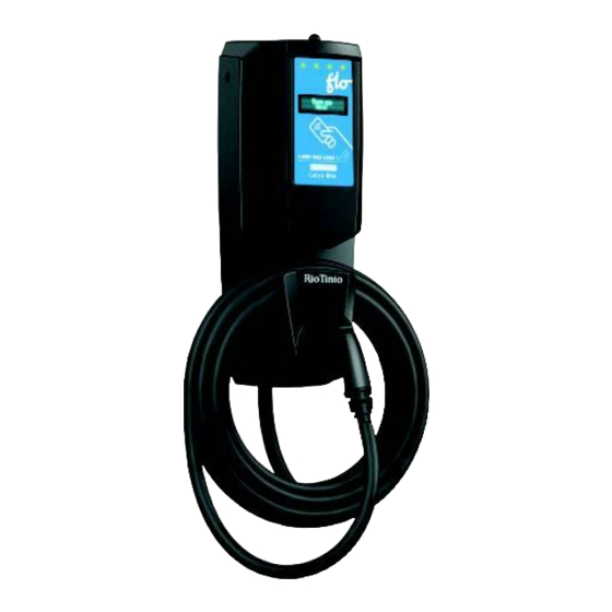
Flo CoRe+ MAX Installation Manual
Hide thumbs
Also See for CoRe+ MAX:
- Installation manual (52 pages) ,
- Installation manual (18 pages) ,
- Installation manual (10 pages)
Advertisement
Quick Links
Advertisement

Related Manuals for Flo CoRe+ MAX


Summary of Contents for Flo CoRe+ MAX
- Page 1 Installation Guide...
- Page 2 Table of Contents 1.1. 1.2. 1.3. 3.1. 3.2. 3.3. 3.4. 3.5.
- Page 3 Changes or modifications to this equipment that have not been expressly approved by FLO may void the user’s authority to operate this equipment. Exposure to radio frequency energy: The radiated power output of the communication modules included in this device is below the limits recommended for the general population for uncontrolled exposure as defined in the FCC standards.
- Page 4 a person’s body, and it must not be co-located or operated with any other antenna in order to comply with the conditions of the FCC grants. Important Safety Instructions 1.2. Read all the instructions before using this product. PLEASE SAVE ALL THE INSTRUCTIONS OF THIS MANUAL. 1.2.1.
- Page 5 When using electrical products, basic precautions should always be followed, including the following. This manual contains important instructions for the CoRe+ MAX model that must be followed during the installation, operation, and maintenance of the unit. This symbol is used to make you aware of important safety information in these instructions.
- Page 6 CAUTION Always use a manual screwdriver. DO NOT use an impact driver for the screws at any time. This will void the warranty. CAUTION To reduce the risk of fire, only connect to a circuit equipped with Rotary appropriate branch circuit overcurrent protection (see the Position Table section 1.3.1.
- Page 7 Site Preparation Considerations Prior to 1.3. Installation Avoid installing the Electric Vehicle Supply Equipment (EVSE) in bad weather conditions. Figure 1 Split Phase 120/240 VAC supply or single phase 120/208 VAC. Refer to Figure 2 in the image below. ...
-
Page 8: Communication Gateway
2. Communication Gateway Install the Communication Gateway prior to the commissioning of the station. The communication gateway is the property of FLO. Fees will be charged if the gateway is damaged, lost, or not installed according to the installation guide. -
Page 9: Installation Instructions
3. Installation Instructions The CoRe+ MAX can be mounted on a wall or pedestal. Depending on the installation, the sections 3.2 to 3.4). power cables can be connected in three different ways (see CoRe+ MAX Pedestal Installation mounted on a CoRe+ MAX pedestal, please refer to the Guide for the pedestal installation procedure prior to the CoRe+ MAX installation. - Page 10 Power Cable Installation Under the Station 3.2. Upper anchor keyhole Protection plate Avoid installing the EVSE in bad weather conditions. Power terminal IMPORTANT The protection plate should always remain over the keyhole. Follow the steps below to install the power cable under the station: 1.
- Page 11 Power Cable Installation from the Back 3.3. Avoid installing the EVSE in bad Protection weather conditions. Upper anchor keyhole plate IMPORTANT: The protection plate should always remain over the keyhole. 1. Attach the head base to the wall or post with Power terminal an anchoring apparatus that can support at least 56.7 kg (125 lbs.) per anchor point (2) in...
- Page 12 3.3.1. Power Cable Entry on a Station with an Electrical Box or CoRe+ MAX Pedestal Avoid installing the EVSE in bad Upper anchor keyhole Protection plate weather conditions. IMPORTANT: The protection plate should Power terminal always remain over the keyhole.
- Page 13 3.3.2. Setting the Current Limit By default, the CoRe+ MAX is set to maximum power in the factory. If your electrical infrastructure does not allow the charging station to operate at maximum power, it can be reduced using the Current Limiter Switch.
- Page 14 2. Using a flat-head screwdriver, gently rotate the switch to the desired position. Refer to the following table to determine the rotary position: Rotary Position Charging Station Current (A) 3. Detach the corresponding maximum current setting label sticker from the label set kit that comes with the unit.
- Page 15 Closing the Station Housing 3.4. 1. Ensure that the gasket on the lip shown below is properly aligned. Gasket 2. Connect the data cable to its respective connector as shown below. WARNING: NEVER CONNECT/DISCONNECT THE DATA CABLE WHEN THE CHARGING STATION IS ENERGIZED.
- Page 16 3. Align the housing groove to the charging station lip and push the housing toward the charging station, ensuring that the gasket stays in place. gasket 4. Apply slight pressure to the front cover, then screw on the top 2 bolts, ensuring that the O-rings stay on the screws.
- Page 17 5. Place the charging cable on the cable holder and the charging connector in the receptacle.
- Page 18 (using the provided access cards) or be connected to FLO’s management system by turning on the communication gateway provided by FLO. Call FLO Services at the number provided on the sticker in front of the charging station to process the commissioning step. If the commissioning is not completed, the station will be limited to 6 A when manufactured in power sharing mode.
- Page 19 3.5.1. Station Status Light Indicator Color Meaning The charging station is ready for session Green - Solid color activation. Session authenticated; the charging station is White - Blinking ready to plug into the electric vehicle (EV). The charging station is plugged in, and energy is Blue - Solid color being delivered.
-
Page 20: Power Sharing
4. Power Sharing The CoRe+ MAX can be configured in standard or power sharing mode. With the integrated power sharing capability of the CoRe+ MAX, a maximum of four charging stations sharing the same 100 A circuit for a total load of 80 A can be connected in parallel to the same branch circuit. - Page 21 Typical Installation Junction boxes allowing the charging stations to be connected 208 or 240 V @ 100 A circuit in parallel to the same branch circuit NOTE: Ensure that the electrical wiring and the associated electrical hardware used to connect the charging stations in parallel comply with the local regulations in place.
- Page 22 5. Operating Instructions 1. Activate the station: Place your card on the reader OR select the station in the mobile app and press “Start a session.” 2. Pick up the connector and unwind the cable to the required length. 3. Plug the connector into your vehicle.
-
Page 23: User Maintenance Instructions
6. User Maintenance Instructions The CoRe+ MAX enclosure is Type 3R, which is intended for indoor or outdoor use and provides a degree of protection against corrosion, windblown dust, rain, splashing water, and hose-directed water. It is designed to remain undamaged by ice, which can form on the enclosure. -
Page 24: Specifications
8. Specifications Specification Description Level 2, 80 A charging station equipped with Description of the charger display and card reader Output connector Output connector: J1772-compliant Split Phase 120/240 VAC supply or single Input connector phase 120/208 VAC (refer to Figure 1 and Figure 2) Maximum configurable output power: 19.2 Maximum output power... - Page 25 FLO_CoRe+ MAX_Installation Guide_V2.0.0_2022-09-20_US_EN FLO CA: © 2022 Services FLO Inc. All rights reserved. FLO, the FLO logo, LEAD THE WAY, and TRACEZ LA VOIE are trademarks of Services FLO Inc. ADDÉNERGIE is a trademark of AddÉnergie Technologies Inc. used under license by Services FLO Inc.
- Page 26 Contact us Telephone: 1 855 543 8356 Email: Info@flo.com Website: Flo.com Eastern office: 2800, Louis-Lumière Street, office 100, Québec, QC, Canada - G1P 0A4 Regional office – Western Canada: #501 – 4190 Lougheed Highway, Burnaby, BC, Canada - V5C 6A8...
Need help?
Do you have a question about the CoRe+ MAX and is the answer not in the manual?
Questions and answers