Flo CoRe+ Installation Manual
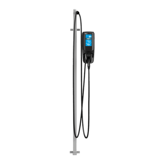
Cable management system and pedestal
Hide thumbs
Also See for CoRe+:
- Installation manual (52 pages) ,
- Installation manual (15 pages) ,
- Installation manual (10 pages)
Table of Contents
Advertisement
Advertisement
Table of Contents

Related Manuals for Flo CoRe+


Summary of Contents for Flo CoRe+
- Page 1 CoRe+ Cable management system and pedestal installation guide...
-
Page 3: Table Of Contents
Table of contents Cable Management System Guide ........4 Wall mounted installation . -
Page 4: Cable Management System Guide
Cable Management System Guide This guide aims at describing how to install a Cable management system on a new charging station or on a device that has already been installed. The Cable management system is reliable, made from aluminum and convenient to use. It’s maintenance free and keeps cables safely off the ground. -
Page 5: Wall Mounted Installation
Wall mounted installation Included material Wall mounted cable management system columns and cable clamp Lower wall mount bracket Upper wall mount bracket Spacing shims Self-adhesive rubber band 6 in X 13/8 in ¼-20 x 2¾ screw, ¼-20 bolt and Split lock washer Specific Tools or Material Required •... - Page 6 Before getting started • Determine where the wall mount (column) will be placed. Allow 12 to 14 in between the column and the charging station. • Determine what wall attachment hardware is required (wall anchors, screws and washers) to securely install the mount brackets to the wall.
-
Page 7: Cable Management System Installation
Cable management system installation First, install one of the two spacing shims and the lower wall mount bracket at the desired height by using two ¼ in diameter screws and appropriate washer. Make sure that both brackets are levelled horizontally. Remark : The lower wall mount bracket can be identified by its factory pre-drilled holes. -
Page 8: Single Charging Station Installation
Single charging station installation Included material Cable management system columns and cable clamp Empty column Column mount bracket Round spacing shims Rectangular spacing shims Self-adhesive rubber band ¼-20 screws (1’’) (for pre-drilled pedestal) Self-drilling screws (1’’) (for pedestal with no holes) Drilling template Drilling template (bottom pedestal) IF THE PEDESTAL IS NOT PRE-DRILLED, USE THE FOLLOWING DRILLING TEMPLATES:... -
Page 9: Cable Management System Installation
BEFORE GETTING STARTED ! When unpackaging the Cable management system, make sure to remove the security screw used to hold the counterweight during transport. ¡ Installing on a new single charging station. First, install the pedestal and the charging station. Refer to CoRe+ MC Installation Guide for pedestal and CoRe+ MC Installation Guide respectively. -
Page 10: Dual Back-To-Back Charging Station Installation
Dual back-to-back charging station installation Included material Cable management system columns and cable clamp Top mounting brackets Round spacing shims Rectangular spacing shims Self-adhesive rubber band ¼-20 screws (1’’) (for pre-drilled pedestal) Self-drilling screws (1’’) (for pedestal with no holes) Drilling template Drilling template (bottom pedestal) IF THE PEDESTAL IS NOT PRE-DRILLED, USE THE FOLLOWING DRILLING TEMPLATES:... -
Page 11: Cable Management System Installation
BEFORE GETTING STARTED ! When unpackaging the Cable management system, make sure to remove the security screw used to hold the counterweight during transport. ¡ Installing on new back-to-back dual charging stations. First, install the pedestal and the two charging stations. Refer to CoRe+ MC Installation Guide for piedestal and CoRe+ MC Installation Guide respectively. -
Page 12: Dual Side-To-Side Charging Station Installation
Dual side-to-side charging station installation Included material Cable management system columns and cable clamp Round spacing shims Self-adhesive rubber band ¼-20 screws (1’’) (for pre-drilled pedestal) Self-drilling screws (1’’) (for pedestal with no holes) Drilling template (for pedestal with no holes) Charging station mount brackets (V-shape mount) and ¼-20 screws Flexible tube Column mount brackets, ¼-20 screws and bolts... -
Page 13: Systems Installation
BEFORE GETTING STARTED When unpackaging the Cable management system, make sure to remove the security screw used to hold the counterweight during transport. ¡ Installing new side-by-side charging stations • First, install the pedestal. Refer to CoRe+ MC Installation Guide for pedestal. •... -
Page 14: Side-To-Side Charging Station Supports And Cable Management
Side-to-side charging station supports and cable managements installation Insert the other end of the flexible tube in the hole provided for this purpose , and screw the bushing from the exterior of the charging station mount bracket so to maintain the flexible tube in place. Remark : This will allow to hold the column during the installation of the bottom column mount brackets. -
Page 15: Positioning The Cable Clamp
Positioning the cable clamp Pull on the cable of the Cable management system to hold the cable clamp in your hand. Remove Torx screws. Determine where to position the charging station cable clamp. Recommendation : The cable portion between the clamp and the charging connector must not touch the ground when the Cable management system is completely retracted. -
Page 16: Positioning The Poster Panel
Positioning the poster panel Matériel fourni / Included material Qty / Qté Poster panel (including two sides) Attachment plate and screws Bolts Washers Rondelle de blocage / Split Lock Washer The top of the columns has embedded screws with rubber caps and washers attached to them. - Page 17 Positioning the poster panel Place this panel on top of the columns by aligning the panel holes with the embedded screws and secure the the assembly. Install the second panel as mentioned in step number 3, and screw the attachment plate to assemble both panels together.
-
Page 18: Pedestal Specifications
©2014 AddÉnergie Technologies Inc . Tous droits réservés . Ce matériel est protégé par les lois sur les droits d’auteur de plusieurs pays et ne devrait pas être modifié, reproduit ou distribué sans le consentement écrit Company Info: Flo Services Inc. d’auteur de plusieurs pays et ne devrait pas être modifié, reproduit ou distribué sans le consentement écrit préallable de AddÉnergie Technologies . -
Page 19: Maintenance And Safety
Maintenance and Safety IMPORTANT SAFETY INSTRUCTIONS - PLEASE DO NOT DISCARD THESE INSTRUCTIONS Carefully read this guide before installing the pedestal 1. This pedestal was designed to be ground-based, it must be mounted on a non-combustible surface. 2. This pedestal was designed to help meeting American Disability Act requirments. 3. -
Page 20: Pedestal Dimensions
Dimensions Dimensions / Dimensions 25.4 cm (10’’) 25.4 cm (10’’) 132 cm 15.2 cm 15.2 cm (52.125’’) (6’’) (6’’) © 2014 ADDÉNERGIE TECHNOLOGIES INC. TOUS DROITS RÉSERVÉS CoRe+ © 2014 ADDÉNERGIE TECHNOLOGIES INC. ALL RIGHTS RESERVED Cable management system and pedestal installation guide... -
Page 21: Pedestal Installation
Pedestal Installation Anchor The installer can use a prefabricated anchor offered by AddEnergie (part number: C+V1- ANCHOR) or make his own using 12” long ½” threaded rods spaced according to the pattern shown on left. Fig. 1: Prefabricated anchor Fig. 2: Threaded rod spacing Concrete Base The base can be prefabricated or made on site using concrete formwork. -
Page 22: Conduit Positioning
Conduit Positioning With 2 conduits and a cascading kit: • The pedestal base opening has been sized to accept 2 PVC conduits up to 2 inches in diameter each, side by side. • The 2 conduits must be placed side by side and centered between the anchor pins which are located on each side of the pedestal’s access door. -
Page 23: Or 2 Devices On Separate Electrical Circuits
1 or 2 Devices on Separate 1 ou 2 dispositifs sur circuits indépendants Electrical Circuits 1 or 2 devices on separate electrical circuits Dispositif électrique NEMA 3R NEMA 3R Electrical Devices NEMA 3R Electrical Devices MALT Grounding © 2014 ADDÉNERGIE TECHNOLOGIES INC. TOUS DROITS RÉSERVÉS Les informations et les spécifications contenues dans ce document sont sujettes aux changements, modifications et ajouts à n’importe quel moment et sans préavis. CoRe+ ©... -
Page 24: Multiple Pedestals, Multiple Devices On Independent Electrical Circuits
Multiple Pedestals, Multiple Multiple piédestaux, multiples dispositifs Devices on Independent sur circuits indépendants Electrical Circuits Multiple pedestals, multiple devices on independent electrical circuits Dispositif électrique NEMA 3R NEMA 3R Electrical Devices NEMA 3R Electrical Devices MALT Grounding LIMITE = DIAMÈTRE DU CONDUIT ET GROSSEUR DES CONDUCTEURS LIMIT = CONDUIT DIAMETER AND WIRE GAUGE ©... -
Page 25: Multiple Pedestals, Multiple Devices Sharing The Same Electrical Circuit
Multiple Pedestals, Multiple Devices Sharing the Same Electrical Circuit NEMA 3R Electrical Devices UL Listed Terminal Block CoRe+ Cable management system and pedestal installation guide... -
Page 26: Multiple Pedestals, Multiple Devices Sharing The Same Electrical Circuit, But With Circuit Breaker For Each Devices
Multiple Pedestals, Multiple Devices Sharing the Same Electrical Circuit, but with Circuit Breaker for each Devices NEMA 3R Electrical Devices UL Listed Circuit Breaker UL Listed Terminal Block CoRe+ Cable management system and pedestal installation guide... - Page 27 Installation or commissioning questions: (877) 505-2674 ext. 203 service@flo.com Services FLO Inc. Eastern office: 2800, Louis-Lumière Street, office 100, Québec (QC) G1P 0A4 CANADA Central office: 7420 Airport Road, Mississauga (ON) L4T 4E5 CANADA United-States Office: 75 South Clinton Ave. Suite 510, Rochester (New-York), 14604, USA Contact Us T.
Need help?
Do you have a question about the CoRe+ and is the answer not in the manual?
Questions and answers