Table of Contents
Advertisement
Advertisement
Table of Contents

Related Manuals for Flo SmartDC V3


Summary of Contents for Flo SmartDC V3
- Page 1 SmartDC Installation Guide...
-
Page 2: Table Of Contents
Table of Contents Specifications 1.1 Technical Specifications 1.2 Integrated Protection 1.3 Standards Compliance Dimensions Center of Gravity Exterior View of the Station Interior View of the Station Installation 6.1 Typical Installation 6.2 Site Preparation 6.3 Safety Measures 6.4 Installation of the Base on the Concrete Slab 6.5 Installation of the Station on the Base 6.6 Connecting the Charging Station 6.7 Installation of the Base Coverings 6.8 Cable Management System (Optional) 6.9 Installaling the Sign Putting the Station into Service 7.1 Before Commissioning 7.2 Commissioning Care and Maintenance of the Charging Station Copyright and Liability... -
Page 3: Specifications
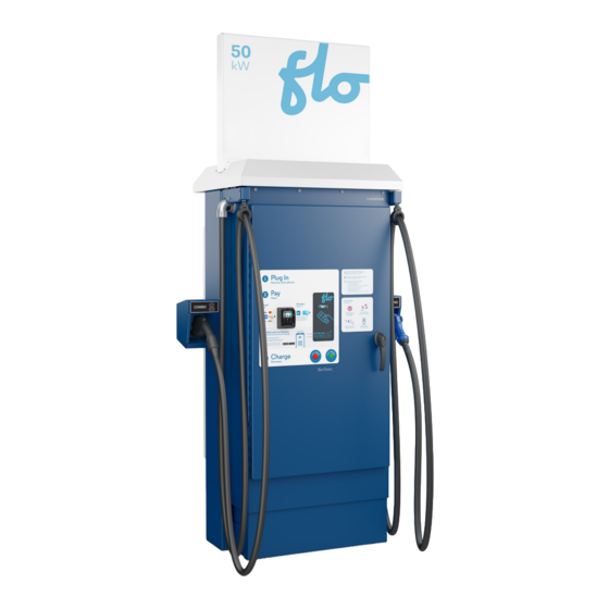
1. Specifications Model : SmartDC Version : V3 Company information : Services FLO Inc. NOTE: The image shows the 50 kW model with the optional Cable Management System (CMS) and credit card reader. -
Page 4: Technical Specifications
1.1 Technical Specifications Specification 50 kW 100 kW / 50 kW+ Type of charging station DC fast charging station Nominal power supply Three-phase 480 Y/277 V Nominal power 54 kVA 108 kVA 65 A 130 A (Select overcurrent protection for (Select overcurrent protection for Nominal current the charging station in accordance the charging station in accordance with the requirements of the local with the requirements of the local jurisdiction) jurisdiction) L1, L2, L3, Neutral terminal: (1) conductor size 4 AWG - 500 MCM (screw terminal) Incoming terminals Grounding terminal: (1) conductor size 14 AWG - 2/0 AWG (screw terminal) Maximum output power 50 kW 100 kW Output connector SAE Combo (CCS1)and CHAdeMO Charging cables 125 A 200 A (maximum output current) Charging cables... -
Page 5: Integrated Protection
1.2 Integrated Protection The following integrated protections are included: • Against voltage surges • Against electrical insulation failures between DC output and ground • Against continuity failures of the protective conductor (PE) between the charger and the vehicle 1.3 Standards Compliance • UL 2202 : Standard for Safety for Electric Vehicle (EV) Charging System Equipment, • UL 2231-1, UL 2231-2 : Standard for Safety for Personnel Protection Systems for Electric Vehicle (EV) Supply Circuits • CSA C22.2 NO. 107.1-16 : General Use Power Supplies • CSA C22.2 NO. 281.1-12, CSA C22.2 NO. 281.2-12 : Standard for Safety for Personnel Protection Systems for Electric Vehicle (EV) Supply Circuits • FCC part 15 Class A • ICES-3(A) / NMB-3(A) NOTE: Consult technical support for more information on calibration. -
Page 6: Dimensions
2. Dimensions NOTE: The picture shows the 1,251 mm (49.25’’) width with the cable management system. The width without the cable management system (CMS) is 1,232 mm (48.50’’). -
Page 7: Center Of Gravity
3. Center of Gravity Center of gravity (approx.) X 25 mm (1’’) Y 940 mm (37’’) Z 58 mm (2’’) * Shown with optional cable management system and credit card reader... -
Page 8: Exterior View Of The Station
4. Exterior View of the Station Display Door handle (padlockable) RFID card reader Cable management system Credit card reader (optional) Heat exchange unit SAE combo (CCS1) connector CHAdeMO connector Stop button Air intake Start button Base cover... -
Page 9: Interior View Of The Station
5. Interior View of the Station Door switch Three-phase power supply terminal block with neutral Grounding terminal AC/DC conversion modules... -
Page 10: Installation
6. Installation 6.1 Typical Installation Master disconnect switch (must be visible from the charging station) Electrical equipment cabinet (metering, protection and distribution) Power cable (three-phase 480 Y/277 Volts + NEUTRAL + GROUND) Parking space for the electric vehicle SmartDC station Protective bollard Concrete slab When a step-down or step-up transformer is required to match the available supply voltage to the 480 volt rating required by the charger, the use of a Y auto-transformer, a Δ/Y transformer, or a Y/Y transformer is acceptable. WARNING: The use of “Open Delta” auto-transformers or transformers with an “Open Delta” primary is prohibited. The product offers mounting configurations that support compliance with the Americans with Disabilities Act (ADA). Validate how to design the site with local authorities. -
Page 11: Site Preparation
6.2 Site Preparation Follow the steps below to prepare the site: 1. The station must be installed on a concrete slab. 2. The surface of the concrete slab must be large enough to allow for the installation of the station and the concrete bollards, while leaving enough space for user traffic. The figure below shows the ideal dimensions and distances to be respected. 3. The soil under the slab must be properly drained and stabilized (according to specific needs) so that it is not affected by frost. 4. An electrical conduit that complies with local regulations and is of appropriate diameter (depending on the wire size) should run the electrical cable under the perimeter of the station, preferably in the front left area under the station perimeter. 5. The anchors and conduit must be positioned to allow for the mounting of the base of the charging station. NOTE: Refer to the site assessment requirements and the anchor supplier’s recommendations for anchor selection. Front Avant ISO View Top View Front View... - Page 12 NOTE: The wiring conduit must be sealed to prevent moisture penetration. IMPORTANT: If there is a wall behind the charging station, a minimum spacing of 24 inches (609.6 mm) must be maintained between the charging station and the wall. IMPORTANT: For indoor installation, make sure that the sticker with the following warning is visible to the user: ‘’WARNING: THIS UNIT IS DESIGNED ONLY FOR CHARGING VEHICLES THAT DO NOT REQUIRE VENTILATION WHILE CHARGING’’ OPTION 1 : BOLLARDS ON THE CONCRETE BASE OPTION 2 : BOLLARDS BESIDE THE CONCRETE BASE...
-
Page 13: Safety Measures
6.3 Safety Measures 1. Ensure that the upstream disconnect is in the open position and follows workplace electrical safety procedures, as required by the local jurisdiction. -
Page 14: Installation Of The Base On The Concrete Slab
6.4 Installation of the Base on the Concrete Slab Align the SmartDC base with the recessed anchors and tighten the bolts to secure the base to the ground. 6.5 Installation of the Station on the Base 1. Remove the access plate to allow the power cable to pass through. - Page 15 2. Lift and handle the station with 2 web slings measuring a minimum of 5.15 m (17’) and having a minimum vertical working load limit of 1,406 kg (3,100 lbs). For example 3. Align the U-profiles (3) of the charging station with the holes in the base.
-
Page 16: Connecting The Charging Station
4. Place the station on the base and tighten the 6 bolts (3 at the front and 3 at the back of the U-shaped channels). 6.6 Connecting the Charging Station 1. Punch a hole in the access plate to match the conductor size and pull the cables through the opening (Cable gland not included). 2. Connect the conductors: a. Connect the three-phase conductors (L1, L2, L3) and the neutral conductor (N) into the terminal with a torque of 56.5 N-m (500 lb-in). b. Connect the grounding conductor into the grounding terminal with a torque of 5.6 N-m (50 lb-in). c. Make sure all conductors are properly labeled (A, B, C, N, G) and that the sequence of the three-phase wires is followed. NOTE Connectors are compatible with copper and aluminum wires. -
Page 17: Installation Of The Base Coverings
3. Place the cable entry plate back in its position and seal it. 6.7 Installation of the Base Coverings 1. Position the side cover plates, then the front and rear base cover plates and tighten the screws (8). -
Page 18: Cable Management System (Optional)
6.8 Cable Management System (Optional) Counterweight installation: 1. Install the aluminum plate with the rubber stoppers and secure it with the bolts (make sure the aluminum plate rests firmly on the floor). 2. Remove the safety screw, and release the counterweight. WARNING: DO NOT put your hands or fingers between the rubber stoppers and the counterweight. 3. Place the plate on the counterweight system. NOTE : This option is only available on the SmartDC 50 kW. -
Page 19: Installaling The Sign
6.9 Installing the Sign Align the panel with the 4 holes on top of the charging station and tighten the 4 bolts to secure the panel. NOTE: If you have any problems installing the top panel, please contact FLO support. Detail A... -
Page 20: Putting The Station Into Service
7. Putting the Station into Service 7.1 Before Commissioning 1. The electrician must ensure that the electrical installation complies with the applicable electrical code, and that the station voltage is within the operating voltage range. 2. Make sure that each of the circuit breakers supplying the converters (50 kW: 2 breakers; 100 kW: 4 breakers) and the control power transformer breaker are in the closed (ON) position. 3. Close and lock the charging station enclosure door. 7.2 Commissioning 1. After the station is powered up, messages will appear on the display screen at the front of the station, confirming that it is now operational. 2. The station will then attempt to communicate with the FLO servers. 3. Once the station and gateway are powered up, please contact FLO technical support to complete the configuration: 1 855 543 8356. -
Page 21: Care And Maintenance Of The Charging Station
8. Care and Maintenance of the Charging Station THIS CHARGING STATION REQUIRES REGULAR MAINTENANCE TO ENSURE PROPER OPERATION AND TO MAINTAIN THE VALIDITY OF THE WARRANTY. PLEASE READ THE WARRANTY, WHICH IS AVAILABLE ON THE WEBSITE AT ALL TIMES. MAINTENANCE MUST BE PERFORMED BY FLO QUALIFIED PERSONNEL. The maintenance consists of: 1. Cleaning or replacing cooling system filters. NOTE It is important to maintain a good air flow inside the charging station to cool some components. 2. Inspection of critical charging station components, such as connector cable assemblies and power conversion modules. We recommend that you perform maintenance on the charging station according to the following timeframes and the event that occurs first: › At least once a year › After 300 hours of use In addition, more frequent maintenance is recommended when the charging station is installed in a dusty environment. -
Page 22: Copyright And Liability
9. Copyright and Liability Name : FLO_SmartDC_Installation Guide_V.2.0.0_2023-05-24_CA_EN Identifiant : PRFM0075 FLO CA: © 2023 Services FLO Inc., All rights reserved. FLO, the FLO logo, LEAD THE WAY, and TRACEZ LA VOIE are trademarks of Services FLO Inc. ADDÉNERGIE is a trademark of AddÉnergie Technologies Inc. used under license by Services FLO Inc. FLO US: © 2023 FLO Services USA Inc., All rights reserved. FLO, the FLO logo, LEAD THE WAY, and TRACEZ LA VOIE are trademarks of Services FLO Inc. used under license by FLO Services USA Inc. ADDÉNERGIE is a trademark of AddÉnergie Technologies Inc. used under license by FLO Services USA Inc. ALL Documents: This document is provided as a general instruction guide. All pictures shown are for illustration purposes only. Actual stations may vary in size or due to product enhancements, in which case additional steps may be required. AddÉnergie Technologies Inc. and its subsidiaries (“AddÉnergie”) reserve the right to alter this document and any product offerings and specifications at any time without notice and AddÉnergie does not guarantee that that this version of the document is current. It is your responsibility to comply with all applicable laws, including those related to accessibility, zoning, and to exercise due diligence when conducting an installation or using this product. Careless installation or use may result in injury or product damage. To fullest extent permitted by applicable laws, AddÉnergie disclaims any liability for personal injury or property damage resulting from the installation or use of this product. ... - Page 23 INSTALLATION OR COMMISSIONING QUESTIONS : Telephone : 1 855 543 8356 Email : service@flo.com CONTACT US: Telephone : 1 855 543 8356 Email : info@flo.com Website : flo.com SERVICES FLO INC. Eastern office: 2800, Louis-Lumière Street, office 100, Québec (QC) G1P 0A4 CANADA Regional Office – Western Canada: #501 –...
Need help?
Do you have a question about the SmartDC V3 and is the answer not in the manual?
Questions and answers