Table of Contents
Advertisement
Quick Links
Advertisement
Table of Contents

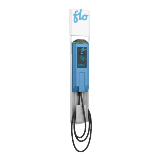
Summary of Contents for Flo SmartTWO
- Page 1 SmartTWO Installation Guide...
- Page 2 IMPORTANT Split Phase 120/240 VAC Supply or 3 phase 120/208 VAC C (must be protected by a 40 A fuse or circuit breaker) Both lines must have 120V between ground. Voltage supply must be grounded. Require 2 lines and 1 ground connection. Neutral is not used. (Refer to Figure 1 and Figure 2).
-
Page 3: Table Of Contents
Table of Contents Specifications ........4 Maintenance and Safety ......5 Configurations .. -
Page 4: Specifications
• This product is approved by the California Type Evaluation Program Electrical standard compliance: Certified ENERGY STAR® 1.2 NOTE: The SmartTWO-M is not certified ENERGY STAR® 1.2. Product Symbols The following symbols appear on the station and in this guide:... -
Page 5: Maintenance And Safety
Maintenance and Safety IMPORTANT SAFETY INSTRUCTIONS - PLEASE DO NOT DISCARD THESE INSTRUCTIONS Carefully read this guide before installing the EVSE 1. This EVSE was designed to be wall-mounted or pole-mounted. 1.1. For the wall-mounted version, you must make sure the wall on which it will be mounted is strong enough, and that you use the appropriate type of anchors. -
Page 6: Configurations
Configurations Recommended Dimensions Pedestal EVSE Pole-mounted EVSE Pedestal EVSE Leave a minimum of 7,6 cm (3’’) Pole-mounted EVSE Leave a minimum of 7,6 cm (3’’) on top of the main structure 20cm on top of the main structure Leave a minimum of 7,6 cm (3’’) to insert the EVSE’s head. -
Page 7: Wall Mount
Wall Mount Single Unit Installation INSTRUCTIONS Patron de perçage: Description Qté Make sure that the available Drilling pattern: Structure principale • Panneau frontal height is a minimum of 216 cm (85”) Couvercle du bornier 8.3 cm Description (3.25’’) Main Structure If the wall requires that anchors to •... - Page 8 Wall Mount Double Unit Installation For double mounting with panel holder (part number: S2-V2- ACCSPSM-01-02), spacers (part number: S2-V2- ACCSPSM-01-05) between the main structures Utiliser des boulons plus longs 3.8 cm (1.5’’) Use longer bolts, 3.8 cm (1.5’’)
- Page 9 Wall Mount Double Unit Installation INSTRUCTIONS: Identify which sides of the main • structure must be assembled face to face and remove their corresponding bolts and screwed plates. Place the main structures one • against the other and join using the four (4) longest carriage bolts you just removed Patron de perçage:...
-
Page 10: Connection
Electrical Connections Remove the block cover. Insert the wires from the bottom of the base and proceed with the connection as shown on the figure below for each EVSE. Piédestal Pedestal Mural Wall-mounted IMPORTANT Installation and maintenance of this EVSE must only be performed by a certified Input: 208/240VAC nominal, 60Hz, 30A electrician to ensure compliance with local... -
Page 11: Front Panel And Base Cover Installation
Front Panel & Base Cover Installation Glisser Slide fro INSTRUCTIONS: Slide the front panels into each of the main structures. Fasten each front panel’s two mounting brackets with bolts and star washers Glisser le panneau frontal en place. Step 1 Step 2 Slide front panels into position. -
Page 12: Station Heads Installation On The Bases
Station Head and Connector Installation Installation of the Charging Station Head on its Base 1. Unscrew the charging port holder 2. Remove the charging port and cable assembly 2.1 Dsconnect the three positions connector and the small black connector 2.2 Unscrew the two brackets 3. -
Page 13: Installation Of The Panel On The Charging Head
Installation of the Panel on the Charging Head • Slide the panel holder onto the charging station head as shown in the image on the left (at this stage, the panel holder is not attached to the head but simply clipped to it). •... -
Page 14: Preliminary Tests And Commissioning
Division of Measurement Standards (DMS) agent if this charging station is intended for use in energy billing mode under commercial application in California. Please call FLO Services for more details. Instructions: Place the charging port in the holder and close the door. -
Page 15: Copyright And Liability
Services FLO Inc. ADDÉNERGIE is a trademark of AddÉnergie Technologies Inc. used under license by Services FLO Inc. FLO US: © 2023 FLO Services USA Inc., All rights reserved. FLO, the FLO logo, LEAD THE WAY, and TRACEZ LA VOIE are trademarks of Services FLO Inc. used under license by FLO Services USA Inc. - Page 16 Contact Us Telephone: 1 855 543 8356 Email: Info@flo.com Website: Flo.com Eastern office: 2800, Louis-Lumière Street, office 100, Québec (QC Canada G1P 0A4 Regional office – Western Canada: #501 – 4190 Lougheed Highway Burnaby (British Columbia, Canada, V5C 6A8 United-States Office: 1270 Pacific Dr, Auburn Hills, MI, United States – 48326...


Need help?
Do you have a question about the SmartTWO and is the answer not in the manual?
Questions and answers