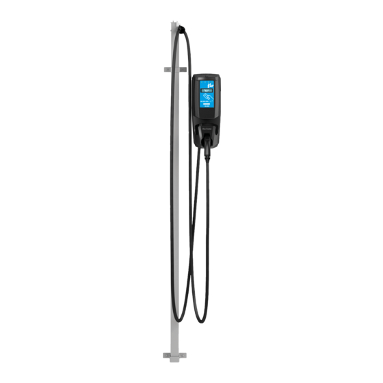
Flo CoRe+ Installation Manual
Anchor
Hide thumbs
Also See for CoRe+:
- Installation manual (52 pages) ,
- Installation manual (27 pages) ,
- Installation manual (15 pages)
Table of Contents
Advertisement
Quick Links
Advertisement
Table of Contents

Summary of Contents for Flo CoRe+
- Page 1 Anchor Installation Guide...
-
Page 2: Table Of Contents
Table of Contents 1. Introduction ............................3 2. Pedestal Anchor ..........................3 2.1. Anchor Specifications ......................3 2.2. Concrete Base Specifications ....................4 2.2.1. Dimensions ..........................4 2.2.2. Conduit Positioning ......................4 3. Installation ............................7 3.1. Cascading Single Station Pedestals ..................7 3.2. -
Page 3: Introduction
Refer to the section below for more information. 2.1. Anchor Specifications The installer can use a FLO prefabricated anchor (part number: ACAN0001 or C+V1- ANCHOR) or make their own using 304.8 mm (12”), 12.7 mm (½”) diameter threaded rods spaced according to the image below. -
Page 4: Concrete Base Specifications
Concrete Base Specifications 2.2. The concrete base can be prefabricated or made on site using a concrete formwork. The dimensions and conduit positioning must be determined based on the environment and layout configuration. 2.2.1. Dimensions The concrete base’s height (H), depth in the ground (D), and surface area (A) must be determined according to the soil type and the freeze/thaw specifications of the installation area. - Page 5 Side-by-Side Conduit Positioning (Compatible for both CoRe+ and CoRe+ MAX pedestals) Use for Single, Dual Side-by-Side, and Back-to-Back (Stations on Back and Front) charging station installations (see sections 3.3.1 to 3.3.3). The conduit positioning should follow the guidelines below: The conduits should be off centered toward the door, with the outside of the conduits at a minimum distance of 32 mm (1.25’’) from the center of the anchor pins.
- Page 6 Back-to-Back Conduit Positioning (Compatible with CoRe+ MAX pedestals only) Use these instructions for the Back-to-Back (Stations on the Sides) charging station installation (see section 3.3.4) The conduit positioning should follow the guidelines below: The conduits should be off centered toward the door, with the outside of the conduits at a minimum distance of 32 mm (1.25’’) from the center of the anchor pins.
-
Page 7: Installation
3. Installation The pedestal base and conduit installation vary according to the charging station configurations. 3.1. Cascading Single Station Pedestals Cascading single station pedestals have the following characteristics: When a single charging station head is mounted on a pedestal, it should always be facing the parking Access door side space it is serving. -
Page 8: Cascading Back-To-Back Station Pedestals - Charging Stations On Front And Back
3.3. Cascading Back-to-Back Station Pedestals – Charging Stations on Front and Back Cascading dual back-to-back station pedestals with charging stations on the front and back have the following characteristics When two charging station heads are placed in the front and back of the pedestal, they should be facing the parking space it is serving. -
Page 9: Copyright And Liability
Document ID: PRFM0003 FLO CA: © 2016-2023 Services FLO Inc., All rights reserved. FLO, the FLO logo, LEAD THE WAY, and TRACEZ LA VOIE are trademarks of Services FLO Inc. ADDÉNERGIE is a trademark of AddÉnergie Technologies Inc. used under license by Services FLO Inc. - Page 10 Contact Us Telephone: 1 855 543 8356 Email: Info@flo.com Website: Flo.com...


Need help?
Do you have a question about the CoRe+ and is the answer not in the manual?
Questions and answers