Otto Bock C2000 Instructions For Use Manual
Hide thumbs
Also See for C2000:
- Instructions for use manual (188 pages) ,
- Service instructions manual (124 pages) ,
- Instructions for use manual (72 pages)

Subscribe to Our Youtube Channel
Related Manuals for Otto Bock C2000


Summary of Contents for Otto Bock C2000
- Page 1 C2000 Instructions for use ....................
- Page 2 [ ] Seat height adjustment [ ] Back angle adjustment [ ] Light [ ] Direction indicator, right [ ] Direction indicator, left [ ] Horn [ ] Warning flasher [ ] Other: *See the section "Use" for more information. C2000...
-
Page 3: Table Of Contents
6.3.1.4.2 Attendant control ..........................6.3.1.4.3 Push-button module ..........................6.3.2 Adjustments by the user ........................6.3.2.1 Adjusting the control device ......................... Delivery ................................Final inspection ..........................Transport to the customer ........................Handing over the product ........................................................... Circuit breaker ........................... C2000... - Page 4 ......................8.11.7 Joystick functions ..........................8.12 Lap belt ............................. 8.12.1 Adaptation ............................8.12.2 ..............................8.13 Luggage carrier ..........................8.14 Lighting ............................. 8.15 Control unit accessories ........................8.15.1 Separate LCD monitor ......................... 8.15.2 Attendant control ..........................8.15.3 Push-button module ..........................C2000...
- Page 5 11.3 Privacy notice ............................. 11.4 Service life ............................Technical data ..............................Appendices ................................ 13.1 Threshold values for wheelchairs transportable by train ................13.2 Required tools ............................ 13.3 Torque values of the screw connections ....................13.4 Sound emission information ......................... C2000...
-
Page 6: Foreword
• Modular design that allows the power wheelchair to be equipped with additional modules and installed equip ment in addition to the main components, such as special controls (see Page 55). • Serviceability due to easy, straightforward access to all components. C2000... -
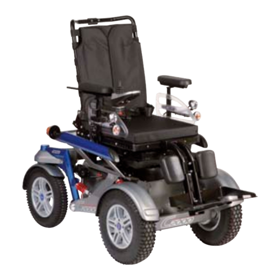
Page 7: Product Overview
Product description 2.2 Product overview Backrest Drive wheel Rear lighting Footrest Luggage carrier Front lighting Charging receptacle Armrest (side panel) Caster wheel Control panel with joystick C2000... -
Page 8: Intended Use
Compliance with all manufacturer specifications and all applic able legal provisions is required. Please contact the manufacturer’s service department for further information (see inside or outside of rear cover for addresses). C2000... -
Page 9: Safety
► Check your skin for intactness before and during use of the product. ► Pay attention to diligent skin care and pressure redistribution during interruptions in using the product. ► If skin damage or other problems occur during use, stop using the product. Consult the qualified personnel. C2000... -
Page 10: Effects Of Electromagnetic Interference On The Product And On The User
EMI problems to your powered wheelchair. 4.5 Side effects The following side effects may occur during use of the product: • Neck, muscle and joint pain • Circulatory disorders, risk of pressure sores Contact a doctor or therapist in case of problems. C2000... -
Page 11: Further Information
M WARNING! Read the instructions for use before using the product. Observe important safety-related information (e.g. warnings, precautions). N Symbol for separate collection of electrical and electronic devices. Components of the power wheelchair and batteries may not be disposed of in household waste. C2000... -
Page 12: Warning Labels
The maximum load capacity (see print on the nameplate; see Page 11) is thereby respectively reduced by the weight of the retrofitted options. 5.2.1 Accessories from other manufacturers If the power wheelchair is being combined with accessories of third-party manufacturers, observe the following notices: C2000... -
Page 13: Storage
The tyres should be replaced every 2 years regardless of wear and tear. • • When power wheelchairs with PU tyres are parked for longer periods, the tyres may become deformed (flat spots). This deformation will go away on its own over time while driving. C2000... -
Page 14: Preparing The Product For Use
The seat height, seat width and seat angle as well as the drive wheel suspension have been preset in accordance with the customer order. Changes to these basic settings may only be made by qualified personnel. Related information is found in the 647G484=* service manual. All parts of the product should be cleaned thoroughly before adjustments are made. C2000... -
Page 15: Safety Instructions
► Turn the power wheelchair off and deactivate the circuit breaker before making any adjustments. Functional tests of the electrical components are excepted from this rule. ► Before performing any work on the seat, ensure that the cushion is sufficiently protected against mechanical, chemical, and thermal effects. C2000... -
Page 16: Adjusting The Standard Seat
Please note that the correction pads are not included in the scope of delivery and cannot be ordered from Ottobock. Please use corresponding foam elements from your inventory. The sitting position can be fine-tuned by using various correction pads in the backrest. C2000... -
Page 17: Adjusting The Belt Length
The power wheelchair can be ordered and equipped with an attendant control. It may be necessary to fit the already installed attendant control to the actual body size of the attendant. Information on operating the attendant control: see Page . Troubleshooting information: see Page 66. C2000... -
Page 18: Push-Button Module
Tipping over, falling of the user due to lack of knowledge ► Instruct the user or the attendant in the proper use of the product when handing it over. The following steps must be performed for the safe handover of the product: C2000... -
Page 19: Use
The installed armrests offer the user additional support for the forearms. 8.2.1 Removing/installing the side panels INFORMATION To remove the side panels with lighting: see Page 47. To make getting in from the side easier or for transportation, the side panels can be removed if needed. C2000... -
Page 20: Adjusting The Side Panels
3) Tighten the 2 Allen head screws. 8.3 Leg support The user's feet can be placed on the leg support. The height of the foot support has been adjusted by qualified personnel to the length of the user's lower leg. C2000... -
Page 21: Folding The Foot Support Up/Down
3) Insert the screws into the mounting holes and retighten them. The calf pads are part of the standard equipment for the power wheelchair. They are mounted on the rails for the attachment of the footrests. Their position can be adapted to the requirements of the user. C2000... -
Page 22: Backrest
1) Push the lock lever down (see fig. 13, item 1). 2) Release the cross bolt on the end of the gas com pression spring or the actuator from the bracket (see fig. 13, item 2). 3) Fold the back support down onto the seat. C2000... -
Page 23: Adjusting The Back Support Angle
Falling, tipping, collision with persons or nearby objects due to interference from electromagnetic fields ► Switch all mobile devices off while driving. ► Turn the control unit off when it is not needed. The power wheelchair is controlled by an enAble50 control device. C2000... -
Page 24: Control Panel
In combination with additional operating steps, holding the button longer (at least 5 seconds) also activates/deac tivates the drive-away lock (see Page 31). [Warning flasher on/off] button All 4 warning flashers are activated/deactivated when this button is pressed. [Horn] button The horn will sound as long as the button is pressed. C2000... - Page 25 20 °C/68 °F. This shortens the range of the power wheelchair accordingly. Moreover at low tem peratures the charge level displayed on the control panel can differ more significantly from the actual battery capacity. The "Charge level" LCD indicator is divided into 7 segments and shows the current battery charge level: C2000...
-
Page 26: Driving Functions
Risk of falling out of the power wheelchair due to lack of restraint ► Always use the installed belt system when driving in public. ► Information about subsequent acquisition and mounting is provided by the qualified personnel that handed the product over to you. C2000... - Page 27 Additional information INFORMATION Even in the event of compliance with all applicable guidelines and standards, alarm systems (e.g. in department stores) may respond to your product. Should this happen, remove your product from the area where the alarm was triggered. C2000...
-
Page 28: Driving Notes
The hand or limb used to operate the joystick should be supported, for example on the side panel arm pad. • The joystick must not be used as the sole support for the hand or limb, because wheelchair movements and bumps could cause a loss of control. C2000... -
Page 29: Switching On And Off
Each time you switch on the control unit, it will return to the previously selected speed level. • The specialist dealer can use the parameter settings to specify the default speed level or default menu of the power wheelchair after it is turned on according to the user's requirements. C2000... -
Page 30: Selecting The Speed Levels
The maximum speed at full deflection of the joystick depends on the selected speed level. • Releasing the joystick automatically activates the brake function, bringing the power wheelchair to a halt. The mechanical brakes are activated automatically when the power wheelchair comes to a stop so that it cannot roll. C2000... -
Page 31: Range
Activating the drive-away lock via separate LCD monitor If a special control is used, then the drive-away lock is activated via the separate LCD monitor. 1) Select Settings Menu > Additional functions Submenu (--- FEHLENDER LINK --- ff.). 2) Activate the function by moving the joystick. C2000... -
Page 32: Steering Lock
► Programming may only be performed by qualified personnel. The manufacturer of the product and the control device manufacturer are not liable in case of damage caused by programming which was not performed prop erly and/or which was not adjusted properly according to the user’s abilities. C2000... -
Page 33: Enabling/Disabling The Brakes
→ A warning will appear on the control panel or LCD monitor when the joystick is deflected: Brake deactivated: warning on control panel/LCD monitor Display Information Brake released (control panel) Brake released (LCD monitor) Locking/activating the brake 1) If needed: Turn the control unit off. C2000... -
Page 34: Batteries/Charging Process
After charging the batteries, the circuit breaker should be deactivated if the wheelchair is not used for more than 3 days. • The power wheelchair control device must be switched off while the batteries are charging to allow all of the charging current to be fed into the battery. C2000... -
Page 35: Battery Charger
Insufficient ventilation of the battery charger while charging Burns due to the battery charger overheating/catching fire ► Make sure the battery charger cannot overheat during the charging process. ► Ensure that the cooling fins/ventilation slots on the back of the device are not covered. C2000... -
Page 36: Seat
► Only use the Ottobock incontinence covers for this product. Contact the qualified personnel to obtain a spare Ottobock cover. 8.10.2 Seat type ® Depending on the order, the product can be fitted with a standard seat, a seat with contoured pads or a Recaro seat. C2000... -
Page 37: Contoured Pads
Nevertheless, you should take the artificial leather cover off from time to time and check whether liquid has gotten into the foam pad through the seams. You should clean the foam pad if this is the case. The incontinence cover is positioned under the seat cover. It protects the foam pad against wetness. C2000... -
Page 38: Cleaning The Covers
1) Hand wash all foam components in warm water at 40 °C [104 °F] using a standard mild detergent. Do not use fabric softener. Rinse thoroughly. 2) Allow to air dry. Do not expose to direct heat sources (e.g. sunlight, stove or radiator). 8.10.4 Recaro® seat The Recaro® seat provides individually adjustable, comprehensive seating comfort. C2000... -
Page 39: Settings
→ For transporting the power wheelchair, place the side panel on the seat. Installing the side panel 1) Insert the side panel into the side panel holder. 2) Re-tighten the thumb screw on the side panel hold er (see fig. 24, item 1). C2000... -
Page 40: Headrest
► To avoid uncontrolled driving movements, ensure that the control unit is always in "Power seat functions" mode before using the power seat functions. ► To avoid hazardous situations, note the correct deflection direction of the joystick (see Page 44). C2000... -
Page 41: Power Seat Height Adjustment
Only use the power wheelchair with the seat height adjustment in its lowest position until the fault is rectified. NOTICE Risk of transportation damage Damage to the product through user error ► Always lower the seat height adjustment feature fully for loading or transportation. C2000... -
Page 42: Power Seat Tilt
► Please also observe the generally applicable safety instructions in the section "Power seat functions" > "Safety instructions" (see Page 40). ► Observe the instructions for use in the sections "Controlling power seat functions" (see Page 43) and "Joy stick functions" (see Page 44). C2000... -
Page 43: Combined Seat Height Adjustment/Seat Tilt
The LCD screen indicates the currently selected seat function (see the following section "Joystick functions"). The driving function is not available at this time and the speed level indicator switches off. • To switch between the various seat functions, press the [Mode] button briefly or move the joystick to the right. C2000... -
Page 44: Joystick Functions
Small length adjustments of the belt by the user or an attendant (e.g. for clothing of different thickness) are pos sible. The belt length can be adjusted on both sides. Excess belt length is taken up by the plastic slider. C2000... -
Page 45: Use
► Under no circumstances may the belt system be used as part of a personal restraint system for transportation in a vehicle for transporting persons with reduced mobility. ► Note that the belt system is only intended as additional stabilisation for the user sitting in the product. C2000... -
Page 46: Luggage Carrier
Damage to product due to breakage ► The maximum load for the luggage carrier is 15 kg. ► Please note that the maximum load of the overall product must not be exceeded, also after loading the lug gage carrier (see Page 68). C2000... -
Page 47: Lighting
3) Insert the side panel back into the side panel hold 4) Re-tighten the thumb screw on the side panel hold Rear lighting The rear lights encompass 2 LED rear lamps with integ rated direction indicators. C2000... -
Page 48: Control Unit Accessories
The status of the driving functions as well as malfunctions/faults are displayed in the Driving menu. • Moving the joystick causes the power wheelchair to begin driving in that direction (see Page 30). • The speed level (see Page 30) is increased each time the [Mode] button on the control panel is pressed briefly. C2000... - Page 49 All important power wheelchair functions can be selected and used from here. Use the joystick to navigate from the Main menu to the Options menu (see below) and the Favourites menu • (see below): Menu Joystick function Move forward: Opens the Driving menu C2000...
- Page 50 Additional functions menu selectable (e.g. drive-away lock, depending on pro gramming) Horn menu selectable: Further submenus allow the horn to be turned on/off LCD environment control functions menu selectable: further submenus allow TV, phone, etc. to be controlled System settings menu selectable: Function is reserved for authorised personnel C2000...
- Page 51 The joystick is used to navigate in this menu, as described for the Options menu. • • Press the [Mode] button on the control panel to return to the main menu. Favourites menu (example) Menu Option First favourites function selectable C2000...
-
Page 52: Attendant Control
The attendant uses the joystick to control the speed and driving direction. When a seat option is activated, the joy stick operates this seat option. [On/Off] button The button is used for switching the power wheelchair on, activating the drive-away lock and switching the wheel chair off. C2000... - Page 53 LCD screen (see the section "Power seat functions" > "Joystick and display functions"). The power seat functions are accessed by depressing of the "M" button for approx. 2 seconds. The currently selected seat function is indicated by the following LEDs: Display Information Power back angle adjustment C2000...
-
Page 54: Push-Button Module
Depending on the power wheelchair model and programming of the push-button module, up to 5 power seat func tions (see Fig., item 1) can be controlled during normal driving operation: Display Information Power seat height adjustment Power seat tilt Power back angle adjustment C2000... -
Page 55: Special Controls
Push-button control • Piko buttons 8.15.5 Adapter cable for Piko button INFORMATION For additional information on the user-specific adjustment of this function: see inside front cover. The power wheelchair may be equipped with an optional adapter cable and Piko buttons. C2000... -
Page 56: Additional Options
By default, the control panel is mounted on the side specified in the order. It can also be mounted on the other side of the power wheelchair later on if the user so desires. Please contact the qualified personnel who delivered the product to you. The depth position of the control panel is subsequently adjustable. C2000... -
Page 57: Belts/Belt Systems
Applies only to chest belts: The chest belt makes contact above the user's sternum (too high) or in the area • of the soft part of the stomach (too low). Adjusting the belt length Notes on correct adjustment are found in the instructions for use included with the belt system. C2000... -
Page 58: Use
→ The shoulder straps should be positioned evenly on both sides on the thorax, and should not be too tight. 2) Pull to check that it is secure. Applying the chest belt Prerequisite: Note the positioning instructions in the previous section. > 1) Unfasten the hook-and-loop closure. C2000... -
Page 59: Overview Of Other Options
Armrest accessories: Special adapters for the armrests in our accessories catalogue • Joystick top: Tetra fork, STICK S80, softball, ball top, sponge ball • Crutch holder • Folding rearview mirror • Tray • Pocket for mobile phone • Centre tray control • Tool kit C2000... -
Page 60: Disassembly And Transport
The transportation size can be reduced in a few steps to make transporting the product easier. Preparing for transport 1) Remove the side panels (see Page 19) 2) Remove the footrest (see Page 21). 3) Fold the backrest forward and onto the seat surface (see Page 22). C2000... -
Page 61: Preparing For Transport
Do not spray the product with a pressure washer. • Observe further cleaning instructions in the section "Belts/belt systems": (see Page 57). 8.19.3 Disinfection 1) Thoroughly clean the pads before disinfecting. 2) Wipe all parts of the product with a disinfectant. C2000... -
Page 62: Maintenance And Repair
Check ratchet mechanism for functionality and firm fit Check for damage to foot supports Padding/straps Ensure padding is in perfect condition Check the attachment straps for wear Check belt buckle for functionality Tyres Check air pressure (see tyre sidewall) C2000... -
Page 63: Repair
Risk of damage to the light ► During installation, ensure that the plates are seated accurately in the housing. ► Ensure that the screws are seated tightly against the plate. INFORMATION Lamp housings and lamps can both be ordered from the specialist dealer. C2000... -
Page 64: Replacing The Battery
The control unit stores a list of all faults that occur. The specialist dealer reads this information, for example during a general overhaul of the power wheelchair. Based on the saved data, the specialist dealer determines future ser vice and maintenance intervals. C2000... -
Page 65: Types Of Notifications
Contact specialist deal troller Defective cabling, soft ware or hardware Battery undervoltage Battery deep discharge Charge as soon as pos sible Battery cable malfunc tioning/faulty connection Check the connection to to the battery the battery (charge the C2000... -
Page 66: Attendant Control Error Overview
Cause Possible measure Backrest LED is flashing Back angle adjustment Faulty cabling or plug con Check cabling/plug con motor fault tact tacts Defective actuator Contact specialist dealer Seat tilt motor fault Faulty cabling or plug con Check cabling/plug con C2000... -
Page 67: Behaviour In Case Of Breakdowns
Detailed information on replacing components as well as information on the required tools can be found in the ser vice manual. 11 Legal information All legal conditions are subject to the respective national laws of the country of use and may vary accordingly. C2000... -
Page 68: Liability
Seat tilt Power: adjustable by up to 30°/45° (depending on the version) Overall width 680 mm Overall height Depending on the seat in use Overall length 1160 mm (with narrow foot support); 1340 mm (with narrow foot sup port folded out); C2000... - Page 69 Protection rating IPX4 Driving data Speed 6 km/h [3.7 mph], 10 km/h [6.2 mph] (see nameplate for precise information) Climbing ability* Climbing ability: 9.5° (17%) Approved climbing ability with lowered seat height adjustment/seat tilt: max. 6° (10%) 9.5° (17%; without seat height adjustment/seat tilt) C2000...
-
Page 70: Appendices
60 mm (2.4") under the foot rest for going for ward at the end of the slope Maximum inclination angle on which the 6° (dynamic stability in all directions) wheelchair will remain stable 9° (static stability in all directions, also when wheel lock engaged) C2000... -
Page 71: Required Tools
► They fully meet the requirements according to the areas of application identified below. Area of application Maximum sound pressure level In enclosed rooms 65 db(A) Outside of enclosed rooms 75 db(A) Depending on the area of application according to ISO 7176-14 C2000... - Page 72 C2000...
- Page 73 C2000...
- Page 74 C2000...
- Page 75 · www.ottobock.de 143441 Moscow Region/Krasnogorskiy Rayon info@ottobock.com.co · www.ottobock.com.co Russian Federation Otto Bock Healthcare Products GmbH Otto Bock de Mexico S.A. de C.V. T +7 495 564 8360 · F +7 495 564 8363 Brehmstraße 16 · 1110 Wien · Austria Prolongación Calle 18 No. 178-A info@ottobock.ru · www.ottobock.ru F +43 1 5267985...
- Page 76 Ihr Fachhändler | Your specialist dealer Otto Bock Mobility Solutions GmbH Lindenstraße 13 · 07426 Königsee/Germany www.ottobock.com...
Need help?
Do you have a question about the C2000 and is the answer not in the manual?
Questions and answers