Table of Contents
Advertisement
Quick Links
Advertisement
Table of Contents

Related Manuals for Otto Bock C1000


Summary of Contents for Otto Bock C1000
- Page 1 C 1000 Service Manual...
-
Page 2: Table Of Contents
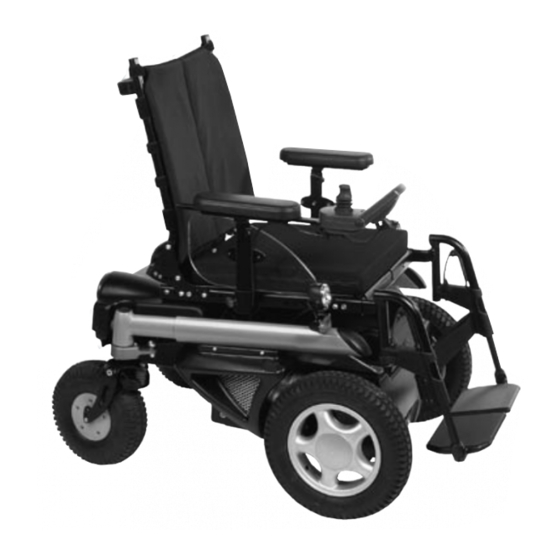
Table of Contents 1 Safety ............................3 2 Preface ............................4 3 Required Tools and Maintenance Plan ..................4 4 Settings / Retrofit / Replacement .................... 7 Control Panel ......................7 Battery / Fuse ..................... 15 Side Panels ......................16 Lighting ....................... - Page 3 C1000 Power Wheelchair Standard seat backrest Standard seat with seat cushion Armrests with clothing protectors Rear lights Control panel Frame Module Footrests Lateral motor cover Front lights Battery case...
-
Page 4: Safety
If you do not have an instructions for use manual, you can order one from the manufacturer (see the overview of all Otto Bock Branches "Otto Bock Worldwide."). Alternatively, you can download the document from our home page at www.ottobock.de or www.ottobock.com). -
Page 5: Preface
2 Preface Regular maintenance is important. It increases safety and prolongs the service life of the product. All rehab products should be inspected and serviced once a year. If the product is used frequently, or if it is used by growing children or patients with changing clinical conditions, we recommend readjusting and servicing the product every 6 months. - Page 6 Side cutting pliers Liquid thread lock "medium Hand drill strength" Twist drills Ø 4 mm, Ø 5 mm Stanley knife with sickle hooked Brush and standard grease blade...
- Page 7 Customer: Maintenance Plan C1000 for Annual Service Item Inspection (check list) Component (group) Function / setting Damages / Screw connections deformations Control unit - Electronics Battery - Liquid level - Battery case - Cables Frame - Spring system - Drive unit sustainer...
-
Page 8: Settings / Retrofit / Replacement
Control Panel Holder All control panel holders for the C1000 are attached to the armrest beneath the armrest pad. To mount or replace a control panel holder, first unscrew the control panel. Next, take the side panel out of its holding device. - Page 9 All control panel holders and LCD holders are attached to the C1000 in the same way. All holders are clamped to the underside of the armrest pad with an iron rail. Standard control panel holder for MCS and Delta control...
- Page 10 Control panel holder, swing-away in parallel, MCS and standard Protective Bow The protective bow is mounted beneath the control panel. Attach it to the underside of the control panel holder and use the two screws and the toothed lock washers to fasten it into place.
-
Page 11: Battery / Fuse
Battery The standard version of the C1000 includes two 12 V lead acid batteries with a capacity of 60 Ah. During the charging process, the water acid mixture is converted into gas for a short time. The liquid level should be checked on a weekly basis and be topped up as needed. - Page 12 Open the battery strap and remove the cover. You can now service the batteries as needed. Battery Charging First connect the battery charger to the charging receptacle, which is located in the side covering. Next, connect the battery charger to the mains. Charging starts automatically. LEDs indicate the charging status on the charger.
- Page 13 - The warranty becomes void in the case of damages resulting from a completely discharged battery! - If the C1000 is not used over extended periods of time, it must be charged once a month. - Only use the battery charger provided by Otto Bock.
- Page 14 Removing / Replacing the Battery Case To remove or replace the battery case, first pull out First remove the fuse, then the battery. The fuse is located in a small box on the front wall of the battery the drawer. You can now remove the batteries and case (see page 14).
- Page 15 Replacing / Installing the Fuse To install or replace the fuse, pull out the battery case and remove the cover as described in the previous sections. The fuse is located in a small box at the front of the battery case. Once you have opened the box, the fuse can be easily pulled out or inserted.
-
Page 16: Side Panels
4.3 Side Panels Changing the Position of the Side Panels Replacing and Setting the Side Panels A side panel attachment device is located on the left To replace the whole side panel, simply loosen the and right sides of the seat frame. thumb screw located on the bottom side of the panel By loosening the two set screws you can change the attachment device. -
Page 17: Lighting
4.4 Lighting Replacing Defective Lamps To change the halogen lamp of the front light, lightly For replacing the front direction indicators, it is push the black engaging lever at the lower end of the best to use a small flathead screwdriver. Insert lamp. - Page 18 Attaching the Front Lights The front lights of the C1000 are attached to the Screw the lighting unit to the metal sheet using a frame by a metal sheet. 6 mm Allen wrench and a 13 mm open-end wrench. There are two pre-drilled holes on the underside of the front part of the frame for attaching the metal sheet.
-
Page 19: Standard Seat
Replacing the Seat The seat frame of the C1000 can be replaced by Next, loosen the screws of the front seat brackets and completely disassembling the seat. remove the seat frame. - Page 20 To change the height of the C1000 standard seat, you have to replace the seat brackets. There are two brackets at the rear, one on the left and one on the right, and both are attached with two hexagon socket head screws.
-
Page 21: Contoured Seat
4.6 Contoured Seat The contoured seat is attached to the seat plate with Attach the back of the contoured seat to the a hook and loop strap. wheelchair backrest with 6 clamps. You can mount the contoured seat on the frame of the standard seat. - Page 22 4.7 Recaro Seat Replacing the Underframe To access the underframe of the Recaro® seat, you Lift the seat slightly and push it backwards. You can have to remove the seat first. To do this, pull the lock now remove the seat. located underneath the seat.
- Page 23 Replacing Seat Modules The seat bottoms of the Recaro® seat modules are attached to the seat frame in the same way as the complete Recaro® seats and are also disassembled in the same way. The modular backrests are hooked onto the seat Next, hook the backrest onto the seat bottom and bottoms.
-
Page 24: Seating System Options
4.8 Seating System Options Assembling / Replacing the Abductors A receiver is used to attach the abductors to the front Once you have attached the receiver, insert the cross brace of the seat frame. abductor holder into the receiver and tighten the To attach the receiver, first drill a hole into the middle screw to fix the abductor in the desired position. - Page 25 Assembling / Retrofitting Straps and Belts Four-Way Chest Strap Kit (only for Recaro® seats) To mount the four-way chest strap kit, you must first Attach the strap end to this tube. There is a bore hole screw the cross bar into the rear of the seat frame. in the middle of the bar.
- Page 26 The covering is attached with three small plastic Once you have removed the covering, you will see nipples. Push them out from the rear side using a two holes on the top left side of the metal plate. screwdriver and remove the covering. Re-drill the upper hole using a 4 mm drill bit.
-
Page 27: Covering Parts
4.9 Covering Parts The C1000 has several covering parts at the rear, front and left and right sides of the wheelchair. Front Covering Side Covering The side covering has three attachment points, two at The front covering covers the battery case and also the top and one at the bottom. -
Page 28: Footrests
4.10 Footrests Different footrest systems are available for the C1000, all offering the same or at least similar setting and attachment options. This makes the footrest systems easier to service or replace. Replacing the Mounting Accessories Assembling / Replacing the Footplate... - Page 29 To replace the footrest receiver, first remove the entire remove the footrest holder. footrest from the C1000. You can then access the two set screws at the rear of the receiver more easily. Loosen these set screws using a 3 mm Allen wrench.
-
Page 30: Front Wheels
4.11 Front Wheels To remove a front wheel, first unscrew the protective Next, remove the 4 wheel screws using a 5 mm Allen cap, which is attached to the wheel with a Phillips wrench. Tighten these screws to a torque of 20 Nm head screw. -
Page 31: Caster / Caster Fork
4.12 Casters / Caster Forks The rear wheels of the C1000 are 10" casters. They are connected to the wheelchair's Servotronic steering system. Mounting the Caster Forks The caster forks of the C1000 come pre-assembled. Insert the fork into the caster fork receiver. - Page 32 Replacing / Repairing the Caster Note: Before mounting or removing a caster, support the frame with suitable objects (e.g. pieces of wood) to prevent it from tipping over or slipping. The wheel must be able to rotate freely. Use two 4 mm Allen wrenches for mounting or removing the caster.
- Page 33 Splash Guard for Caster Fork Repair the inner tube with a standard bicycle repair The splash guard for casters is attached to the kit or replace the tube with a new one. caster fork with two hexagon socket head screws. A 3 mm Allen wrench is required for replacing this component.
-
Page 34: Frame / Drive Unit Sustainer / Motors
Note: Do not forget to secure the wheelchair to prevent it from slipping or tipping over. Support the C1000 so that the driving wheels are able to rotate freely and the chair is unable to slip. - Page 35 The oscillating cranks are attached to the drive unit sustainer with one screw. Motors When installing the motors in the C1000, make sure Before removing the motors, unscrew the brake that the right motor is installed on the left side and the release.
- Page 36 Please contact your dealer. The brake release is attached to the right side of the C1000 with the wheelchair lying on its side, as shown in the photo. When attaching the brake release, make sure that the short cable is under the longer cable.
- Page 37 Adjusting a slack cable when you begin adjusting it. Frame and Drive Unit Sustainer The frame of the C1000 is placed on the drive unit For reinforcement, a steel rail is mounted to the drive sustainer and secured with two screws on each unit sustainer under the supporting surface of the side.
- Page 38 Tighten the first two screws and then mount the seat Once you have tightened all 4 screws on each side, brackets. Fasten each bracket with two screws. A use a plastic hammer to apply a black plastic cap to 6 mm Allen wrench is required. each screw head.
-
Page 39: Control Unit
Connect all plugs, attach the protective cover and If the C1000 is equipped with more than three electric screw in the cover on the left and right sides with a options, the additional module is required. -
Page 40: Electric Options
Electric Lift Seat The frame of the C1000 lift seat is attached to the The attachment at the front is also the same as the frame with seat brackets, just like the frame of the attachment for the standard seat. - Page 41 Lead the cables for the lift seat to the control box. The lift seat has a contact which tells the motor when Fasten the individual cables together every 10 cm the end position has been reached so the motor can using cable ties.
- Page 42 Before operating the seat, make sure that the spring Lead the cable backwards as shown in the photo is hooked to the lift frame. and fasten the cables approximately every 10 cm with cable ties. Make sure that cables will not be hindered when the lift seat or seat tilt functions are used.
-
Page 43: Accessories
Crutch Holder Rear-View Mirror The crutch holder of the C1000 is mounted to the side panel on the underside of the arm pad. The crutch holder is screwed into two bore holes in the arm pad. - Page 44 Otto Bock HealthCare GmbH Lindenstraße 13 · D-07426 Königsee Otto Bock HealthCare GmbH has been certified by the German Society for the Certification of Quality Assurance Systems (DQS) in accordance with DIN EN ISO 9001 standard, reg. no. 779 (management system)
Need help?
Do you have a question about the C1000 and is the answer not in the manual?
Questions and answers