Table of Contents

Related Manuals for MGE UPS Systems Upsilon STS 30A


Summary of Contents for MGE UPS Systems Upsilon STS 30A
- Page 1 All manuals and user guides at all-guides.com www.mgeups.com MGE UPS SYSTEMS Galaxy 3000 10 - 30 kVA Upsilon STS 30A-60A-100A-160A 250A-400A-600A Installation and user manual LE SAVOIR FAIRE MERLIN GERIN - Page 1 34020113EN/AA...
- Page 2 All manuals and user guides at all-guides.com Page 2 - 34020113EN/AA...
- Page 3 To take into account evolving standards and technology, equipment may be modified without notice. Indications concerning technical characteristics and dimensions are not binding unless confirmed by MGE UPS SYSTEMS. This document may be copied only with the written consent of MGE UPS SYSTEMS. Authorised copies must be marked "Upsilon STS Installation and User Manual, nr 3402011300".
- Page 4 All manuals and user guides at all-guides.com Foreword Using this document Information may be found primarily by consulting: the contents, the index. Pictograms Document Display Important instructions that must Go up or down one page Up / down selection be followed Select date for event log Information, advice, help Other selection...
-
Page 5: Table Of Contents
All manuals and user guides at all-guides.com Contents Presentation Upsilon STS 30 - 60 - 100 - 160 - 250 A (cabinet 1400 mm high) ..........7 Upsilon STS 30 - 60 - 100 - 160 - 250 - 400 - 600 A (cabinet 1900 mm high) ......7 Access to control and connections .................. - Page 6 All manuals and user guides at all-guides.com Contents Appendix Technical data ..........................27 Output currents and voltage ......................27 Thermal characteristics ......................... 27 Noise level ............................ 27 Cable sizes ........................... 27 Recommended protection devices upstream of Upsilon STS ............. 27 Permissible-overload curve ......................
-
Page 7: Presentation
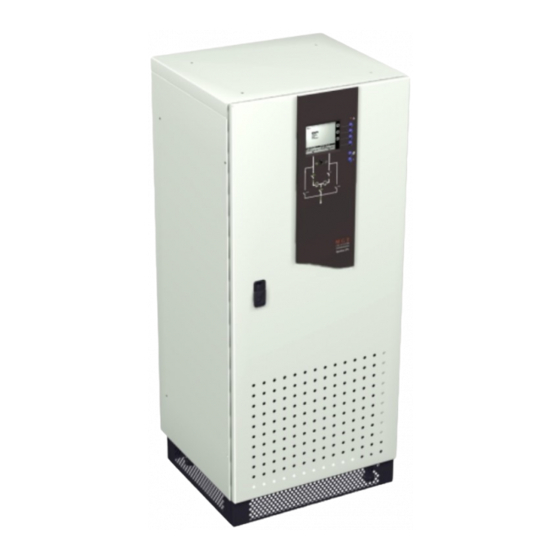
All manuals and user guides at all-guides.com 1. Presentation 1.1 Upsilon STS 30 - 60 - 100 - 160 - 250 A (cabinet 1400 mm high) Dimensions in mm Height Width Depth 1400 Weight in kg Upsilon STS 30 - 60 - 100 A 157 kg 174 kg 160 - 250 A... -
Page 8: Access To Control And Connections
All manuals and user guides at all-guides.com 1. Presentation 1.3 Access to control and connections Upsilon STS 30 - 60 - 100 - 160 - 250 A (cabinet 1400 mm high) Switch Q1 for Source S1 Circuit breaker Q5 for control electronics power supply Circuit breaker Q6 for control electronics power supply... -
Page 9: Man / Machine Interface
All manuals and user guides at all-guides.com 1. Presentation 1.4 Man / machine interface General alarm Graphic display Menu Menu NORMAL OPERATION 17 A Function buttons 1 KW 6 KVA Transfert Alarme Alarme PF 0.3 Mesures Mesures Etats Etats volt Historique Historique UPS 1... -
Page 10: Relay Communication Card
All manuals and user guides at all-guides.com 1. Presentation 1.5 Relay communication card Screws to secure the cover Card fixing holes Protection cover Openings for cables Output terminal block Input terminal block Screws to block cables 1.6 JBus communication card RS232 connector RS485 connector Page 10 -... -
Page 11: Installation
All manuals and user guides at all-guides.com 2. Installation 2.1 Positioning Upsilon STS 30 - 60 - 100 - 160 - 250 A (cabinet 1400 mm high) 1 - Unclip the base panels 14 . 2 - Set the cabinet to a level position using the adjustable foot pads 15 . -
Page 12: Power Connections
All manuals and user guides at all-guides.com 2. Installation 2.2 Power connections See section 6.1 for information on sizing protection devices and cables (Appendix, Technical data). Two cables maximum may be used per phase. Upsilon STS 30 to 250 A Input: 3 phases + PEN Output: 3 phases + PEN... -
Page 13: Upsilon Sts 30 To 250 A With Input: 3 Phases + Pen, Output: 3 Phases + Pe
All manuals and user guides at all-guides.com 2. Installation Upsilon STS 30 to 250 A Input: 3 phases + PEN Output: 3 phases + PE See section 1.3 for information on accessing the connections. Connections are made using lugs connected to threaded studs (diameter 8 mm). -
Page 14: Upsilon Sts 400 To 600 A With Input/Output: 3 Phases + Pen
All manuals and user guides at all-guides.com 2. Installation See section 6.1 for information on sizing protection devices and cables (Appendix, Technical data). A maximum of four cables may be used per phase. Upsilon STS 400 to 600 A Input: 3 phases + PEN Output: 3 phases + PEN See section 1.3 for information on accessing... -
Page 15: Upsilon Sts 400 To 600 A With Input: 3 Phases + Pen, Output: 3 Phases + Pe
All manuals and user guides at all-guides.com 2. Installation Upsilon STS 400 to 600 A Input: 3 phases + PEN Output: 3 phases + PE See section 1.3 for information on accessing the connections. Connections are made using lugs connected to two threaded studs per phase L1 L2 L3 L1 L2 L3 L1 L2 L3... -
Page 16: Cable Running For Cables Entering Through The Top Of The Upsilon Sts 30 To 250 A Cabinet
All manuals and user guides at all-guides.com 2. Installation Cable running for cables entering through the top of the Upsilon STS 30 to 250 A cabinet Cable-running zone for cables entering through the top Cable gland plate that must be drilled to cable size 2.3 Connection of the emergency power off terminal block 1 - Remove the jumper from terminal block... -
Page 17: Connection Of The Communication Cards
All manuals and user guides at all-guides.com 2. Installation 2.4 Connection of the communication cards Tie the cables to the cable way on the door. Do not run the control wires with the power cables. Two slots are available in the card cage 5 for additional cards. -
Page 18: Connection Of The Relay Communication Card
All manuals and user guides at all-guides.com 2. Installation 2.6 Connection of the relay communication card Before proceeding, disconnect all power sources connected to the card. Do not mix very low safety voltage (VLSV) and non-VLSV circuits on the card outputs. 1 - Remove the screws 41 and the protection cover 43 . -
Page 19: Operation
All manuals and user guides at all-guides.com 3. Operation Make sure that the voltages and frequencies of the two sources S1 and S2 are identical. Make sure that the voltages of the two sources S1 and S2 are the same as the rated voltage (400 V) of Upsilon STS, otherwise see section 3.5 (Customization). -
Page 20: Normal Mode: Operation On Preferred Source S1
All manuals and user guides at all-guides.com 3. Operation 3.3 Normal mode. Operation on preferred source S1 Operation on the preferred source During normal operation on the preferred source S1, LEDs 24 , 29 , 30 , 31 , 32 , 33 , 36 and 38 are on in green. -
Page 21: Manual Transfer To An Out-Of-Phase Alternate Source
All manuals and user guides at all-guides.com 3. Operation Manual transfer to an out-of-phase alternate source When the two sources are not in phase, it is possible to force manual transfer using the commands on the screen, after entering a password. -
Page 22: Display Screens
All manuals and user guides at all-guides.com 3. Operation 3.4 Display screens Initial screen Main screen DOWNGRADED MODE MAIN MENU 17 A Transfer 1 KW 6 KVA PF 0.3 Alarms 0 1 0 1 UPS 1 preferred UPS 2 Status 1 0 1 0 0 1 0 1 V1 244 V... -
Page 23: Upsilon Sts Customization
All manuals and user guides at all-guides.com 3. Operation 3.5 Upsilon STS customization 1 - Press the menu button 26 . 2 - Select "Setup", then "Customization" using the function buttons 23 marked 3 - Confirm the order by pressing the function button 23 marked 4 - Enter the password. -
Page 24: Customization Of The Relay Communication Card
All manuals and user guides at all-guides.com 3. Operation 3.6 Customization of the relay communication card Factory setting Signals available on each contact Inputs - Memorised faults reset command. - Memorised faults reset command. - Selection command for source S1. - Selection command for source S2. -
Page 25: Maintenance
All manuals and user guides at all-guides.com 4. Maintenance 4.1 Identification of anomalies General-alarm S1 31 or S2 32 Static-switch Buzzer System output Meaning LED 21 LED 33 or 34 LED 38 Beeps Internal STS fault. Source outside Beeps tolerances, load still supplied. -
Page 26: Environment
UPS recycling at the end of service life MGE UPS SYSTEMS undertakes to recycle, by certified companies and in compliance with all applicable regulations, all products recovered at the end of their service life (contact your MGE UPS SYSTEMS branch office). -
Page 27: Appendix 6.1 Technical Data
All manuals and user guides at all-guides.com 6. Appendix 6.1 Technical data Output currents and voltage Rated output current: 30 A 60 A 100 A 160 A 250 A 400 A 600 A Input and output voltage: Rated operating voltage: 380 V / 400 V / 415 V Maximum voltage: 498 V (415 V +20%) -
Page 28: Simplified Diagrams
All manuals and user guides at all-guides.com 6. Appendix 6.2 Simplified diagrams Upsilon STS simplified diagram Source 1 Source 2 Upsilon STS Static-switch control/monitoring Q1BP Q2BP To the load Simplified diagram of an installation Preferred sources Alternate sources Upsilon STS Upsilon STS Upsilon STS To the load... -
Page 29: Glossary
All manuals and user guides at all-guides.com 6. Appendix 6.3 Glossary Alternate source Backup source that steps in if the preferred source fails. JBUS communication card Internal card implementing the JBus protocol on a serial link to supply the user with system information. -
Page 30: Index
All manuals and user guides at all-guides.com 6. Appendix 6.4 Index Alarms ................25 Layout of components ............8 Anomalies ..............25 LEDs ................9, 25 Links RS232 ..............10 RS485 ..............10 Buzzer ................25 Losses ................27 Cable sizes ..............27 Man / machine interface ...........
Need help?
Do you have a question about the Upsilon STS 30A and is the answer not in the manual?
Questions and answers