Table of Contents
Advertisement
Quick Links
Software Release:
[Application Version 2.8.10128; Configuration Version 2.8.10457]
To see this manual in Spanish, German, French or Italian, please go to
In order to consistently bring you the highest quality, full-featured products, we reserve the right to change our
specifications and designs at any time.
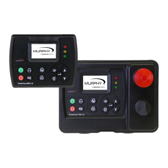
PowerCore
MPC-10 Engine Controller &
TEC-10 Panel
Operations Manual
www.fwmurphy.com/mpc10
Application 2.8.10128; Configuration 2.8.10457]
Software Release: [
®
00-02-0939
2016-04-19
Section 40
Advertisement
Table of Contents

Subscribe to Our Youtube Channel
Related Manuals for Enovation Controls MURPHY PowerCore MPC-10


Summary of Contents for Enovation Controls MURPHY PowerCore MPC-10
- Page 1 Software Release: [Application Version 2.8.10128; Configuration Version 2.8.10457] PowerCore ® MPC-10 Engine Controller & TEC-10 Panel Operations Manual To see this manual in Spanish, German, French or Italian, please go to www.fwmurphy.com/mpc10 Application 2.8.10128; Configuration 2.8.10457] Software Release: [ In order to consistently bring you the highest quality, full-featured products, we reserve the right to change our specifications and designs at any time.
- Page 2 Software Release: [Application Version 2.8.10128; Configuration Version 2.8.10457] ENOVATION CONTROLS has made efforts to ensure the reliability of the MPC-10 / TEC-10 and to recommend safe use practices in system applications. Please note that in any application, operation and controller failures can occur. These failures might result in full control outputs or other outputs that might cause damage to or unsafe conditions in the equipment or process connected to the MPC-10 / TEC-10.
- Page 3 Software Release: [Application Version 2.8.10128; Configuration Version 2.8.10457] The MPC-10/TEC-10 can be set as an AutoStart Controller. Please be cognizant at all times of hands and other objects that are in close proximity to the machine(s) being controlled as they may commence operation suddenly and without warning. LENS CLEANING PROCEDURES The lens on the MPC-10/TEC-10 is composed of Polycarbonate materials.
- Page 4 Software Release: [Application Version 2.8.10128; Configuration Version 2.8.10457] - THIS PAGE INTENTIONALLY LEFT BLANK - Section 40 00-02-0939 2016-04-19...
-
Page 5: Table Of Contents
Software Release: [Application Version 2.8.10128; Configuration Version 2.8.10457] Table of Contents Introduction ..........................7 Murphy PowerCore 10 (MPC-10 / TEC-10)..............7 User Interface .......................9 Accessing the Menu ........................ 10 Main Menu ..........................11 Start/Stop Settings ........................16 Single Contact Start/Stop ................... 16 Two Contact Maintained Start/Stop (commonly known as Floats) ...... - Page 6 Software Release: [Application Version 2.8.10128; Configuration Version 2.8.10457] Throttle Menu ......................32 Input / Output Menu ....................33 Application Configuration ................... 35 Start / Stop Timers ..................... 39 Communication ......................40 Modbus Registers ...................... 40 MPC-10 Specifications ......................46 Interface ........................46 Power Supply ......................
-
Page 7: Introduction
Software Release: [Application Version 2.8.10128; Configuration Version 2.8.10457] Introduction This document is designed to familiarize a user with the MPC-10 / TEC-10 and how to navigate the interface and modify the settings when installing and operating the controller. The Quick Set Up guide assists with establishing the different functions in the MPC-10 / TEC-10 System Controller. - Page 8 Software Release: [Application Version 2.8.10128; Configuration Version 2.8.10457] • Check Safe To Start: This is a non-timed state that will check to ensure the engine can start safely. • Auto Stop Delay: (available in Auto Mode only) The auto stop condition is ignored and must remain active throughout this delay or the delay is reset to zero.
-
Page 9: User Interface
Software Release: [Application Version 2.8.10128; Configuration Version 2.8.10457] • Post Warm-up Lockout Delay (setup):This delay begins timing when the warm-up delay expires. During this delay, the selected function is ignored. When this delay expires, the selected function is armed. During the duration of this delay, the selected function can cycle from active to not active and not reset the delay. -
Page 10: Accessing The Menu
Software Release: [Application Version 2.8.10128; Configuration Version 2.8.10457] • Manual Throttle Increase Key – Allows the operator to manually increase the engine throttle in Manual Mode. • Manual Throttle Decrease Key – Allows the operator to manually decrease the engine throttle in Manual Mode. •... -
Page 11: Main Menu
Software Release: [Application Version 2.8.10128; Configuration Version 2.8.10457] The password will be entered left to right. Utilize the up and down arrows, and press the Enter button after each correct number: Entering this password will allow full access to the menu. If you enter the wrong password, it will reset the display to 0000, allowing you to restart the entering process. - Page 12 Software Release: [Application Version 2.8.10128; Configuration Version 2.8.10457] Engine Settings The Engine Settings menu allows the operator to establish common user-configurable parameters that would be changed from factory default settings when pairing the controller to an engine. This menu allows the operator to choose whether the engine is J1939 or mechanical; the engine’s speed source;...
- Page 13 Digital Out [1A, B(-)] NOTE: Although the functionality exists to set all analog and digital inputs to the same function, Enovation Controls strongly advises against this. Application Configuration The Application Configuration menu is where an operator will set up the controller’s Auto Start Functions and Auto Throttle Methods, if the intended use is as an auto start and/or auto throttling controller.
- Page 14 Software Release: [Application Version 2.8.10128; Configuration Version 2.8.10457] Air Compressor The Air Compressor application houses the auto start functions and auto throttle methods meant used engine-driven compressor applications. MPC-10 / TEC-10 allows for the compressor to start/stop and maintain a desired pressure during operation.
- Page 15 Software Release: [Application Version 2.8.10128; Configuration Version 2.8.10457] Chipper The Chipper application houses the auto start functions and engage/disengage methods meant to be used on Chippers. The operator can also choose between Chipper types, On- Off-On or Dumping. The functions available are: Auto Start/Stop Functions •...
-
Page 16: Start/Stop Settings
Software Release: [Application Version 2.8.10128; Configuration Version 2.8.10457] Communication The Communications menu allows the operator to choose the type of RS485 communications such as PVA Gauge, Modbus or Local Display. The menu also allows for the operator to choose the RS485 slave address and RS485 Serial setup. -
Page 17: Adjusting The Brightness
Software Release: [Application Version 2.8.10128; Configuration Version 2.8.10457] Adjusting the Brightness 1. Access Menu/System/Brightness and press [Enter]. 2. Utilize the Up and Down arrows to adjust the Brightness (values of 0 to 100), and press [Enter] when the desired number appears. 3. -
Page 18: Setting To Auto Start On Local Start Key
Software Release: [Application Version 2.8.10128; Configuration Version 2.8.10457] Setting to Auto Start on Local Start Key 1. Access Menu/Application Configuration/Auto Start_Stop Function/Local Start Key and press [Enter] (not available for Frost Protection). 2. Press the [Menu] key to leave the Menu Setup screens. Setting to Auto Start on Float Inputs 1. -
Page 19: Setting To Auto Start On Temperature
Software Release: [Application Version 2.8.10128; Configuration Version 2.8.10457] Setting to Auto Start on Temperature 1. Access Menu/Application Configuration/Frost Protection/Auto Start_Stop Function/Temperature Transducer. Press [Enter]. 2. Arrow down to Temperature Transducer. 3. Establish a Start and Stop Temperature, and press [Back] twice. 4. -
Page 20: Additional Screens
Software Release: [Application Version 2.8.10128; Configuration Version 2.8.10457] Additional Screens Figure 8: Main Screen This is the main screen, and it displays actual and target RPM, Mode of Operation, Timer progress, % Soot Level, % DEF Level and current State, along with icons and warnings. Figure 9: 4 Up Screen This is the first 4 up screen, displaying engine RPM, oil pressure, engine temperature and battery voltage. - Page 21 Software Release: [Application Version 2.8.10128; Configuration Version 2.8.10457] Figure 11: Auto Start/Stop Type This screen displays the auto start/stop type and will also illustrate the throttling method for the auto start/stop. Figure 12: Regeneration Mode This is the Tier 4 Regeneration screen that is selected to be shown in the Tier 4 menu. This screen shows and allows the user to select the regeneration mode without accessing the menu, if desired.
- Page 22 Software Release: [Application Version 2.8.10128; Configuration Version 2.8.10457] Figure 14: Digital Output Status This screen will allow the operator to see what the digital output functions are set to without accessing the menu and the active setting which informs the user of the output status. Figure 15: Relay Status This screen will allow the operator to see what the relay status functions are set to without accessing the menu and the active setting which informs the user of the relay status.
-
Page 23: Iso Icons
Software Release: [Application Version 2.8.10128; Configuration Version 2.8.10457] Figure 17: Analog Input Status This screen displays the Analog Input’s function selected in the menu for each input. Figure 18: Service Life Remaining Screens These screens provide a list of service reminders and the hours left until the internal alarm will display the services needed. - Page 24 Software Release: [Application Version 2.8.10128; Configuration Version 2.8.10457] Icon Description Displays when engine aftertreatment is in need of regeneration. This is due to the aftertreatment filter reaching the engine manufacturer's set soot level for a regeneration to occur. Displays when the Engine ECU has inhibited a regeneration from occurring.
-
Page 25: Icon Troubleshooting
Software Release: [Application Version 2.8.10128; Configuration Version 2.8.10457] Icon Description Current Oil Pressure Current RPM Ambient Temperature Oil Temperature System Level Suction Pressure Percent Load at Current RPM Current Engine Temperature Battery Voltage Icon Troubleshooting The warnings and shutdowns internally generated by the controller will show an Internal Fault on the top of the screen when a fault is displayed. -
Page 26: Menu Glossary
Software Release: [Application Version 2.8.10128; Configuration Version 2.8.10457] Menu Glossary System Date/Time: allows the setting of the controller’s date and time. Pressure Units: allows the selection of psi, kPa or BAR for pressure designation. Factory set to PSI. Temperature Units: allows the selection of Fahrenheit or Celsius for temperature designation. Factory set to Fahrenheit. -
Page 27: Engine Settings
Software Release: [Application Version 2.8.10128; Configuration Version 2.8.10457] Set Machine Hours: allows the operator to set the internal hours of the controller if Engine Type is set to Mechanical or ECU Hour Select is set to Internal. View Event History: allows the viewing of stored alarms. Clear Event History: allows the clearing of stored events (alarms). -
Page 28: Advanced Engine Settings
Software Release: [Application Version 2.8.10128; Configuration Version 2.8.10457] Speed Calibration: allows the setting of the correct number of flywheel teeth or engine alternator pulses for mechanical engines. Factory set to 150. WarmUp Speed: allows the setting of the speed of the engine during the warm-up phase. This speed setting must be at or above the minimum engine speed setting. - Page 29 Software Release: [Application Version 2.8.10128; Configuration Version 2.8.10457] Auto Stop Delay: this auto stop condition must remain active throughout this delay for an auto stop to occur. If the auto stop condition is removed during this delay, the delay is reset to zero. Factory set to 00.00.03 ECU Stabilize Timer: on start-ups, this delay allows the ECU to stabilize and broadcast on the CAN bus prior to actual cranking.
- Page 30 Software Release: [Application Version 2.8.10128; Configuration Version 2.8.10457] Bubble Lockout Setup: this is a setup for a delay that begins timing when the selected functions are active. If the selected functions are removed during this delay, the delay resets to zero. If the selected functions remain active throughout this delay, the selected action for the parameter will occur.
- Page 31 Software Release: [Application Version 2.8.10128; Configuration Version 2.8.10457] Overspeed Shutdown: a shutdown will occur when the engine speed reaches this set point. Factory set to 2400 RPM. High Level Warning: an alarm will occur if the level reaches this set point. Factory set to 0.0 High Level Shutdown: a shutdown will occur if the level reaches this set point.
-
Page 32: Throttle Menu
Software Release: [Application Version 2.8.10128; Configuration Version 2.8.10457] High Gearbox Pressure Warning: an alarm will occur when the pressure reaches this set point. Factory set to 0 PSI. High Gearbox Pressure Shutdown: a shutdown will occur when the pressure reaches this set point. -
Page 33: Input / Output Menu
Software Release: [Application Version 2.8.10128; Configuration Version 2.8.10457] Throttle Inc/Dec Pulse Delay: format of # mS. The amount of delay time before pulsing the throttle. Increase this value for slower engine response, or decrease this value for faster engine response. Factory set to 250mS. - Page 34 Software Release: [Application Version 2.8.10128; Configuration Version 2.8.10457] Analog Inputs (1-3): for each of the analog inputs, the ability to select the following parameters exists: Analog input 1. Factory set to Disabled Analog Input 2. Factory set to Disabled Analog Input 3. Factory set to Disabled Function: Disabled 4-20mA Suction Pressure...
-
Page 35: Application Configuration
Software Release: [Application Version 2.8.10128; Configuration Version 2.8.10457] DO3 (B-, 1A). Factory set to Throttle Decrease DO4 (B-, 1A). Factory set to Throttle Increase Function: Prestart 1 Delay Please see Timers on page 23. Prestart 2 Delay Please see Timers on page 23. Crank: Please see Timers on page 23. - Page 36 Software Release: [Application Version 2.8.10128; Configuration Version 2.8.10457] Start which may be the most used in this application. The key feature of this application is the auto throttling method. This feature allows the controller to manage the pump’s throttle in order to maintain a pressure in the hose during irrigation.
- Page 37 Software Release: [Application Version 2.8.10128; Configuration Version 2.8.10457] 10. The Disengage output turns on. 11. The display will read Feed Reverse. 12. For Feed Off, the operator presses and holds the Enter button for 5 seconds. 13. If on, the Engage output turns off. 14.
- Page 38 Software Release: [Application Version 2.8.10128; Configuration Version 2.8.10457] 8. To exit the Autofeed Override feature, press and hold the Back button for 5 seconds. This will return the controller to the main menu. Press the menu button to return to the front display. Auto Start / Stop Function Single Contact (Pump All Purpose, Air Compressor, Hose Reel Irrigation, Frost Protection, Chipper)
-
Page 39: Start / Stop Timers
Software Release: [Application Version 2.8.10128; Configuration Version 2.8.10457] Start / Stop Timers NOTE: When the engine is started using one of the start timers, the timer which started the engine is the timer which will stop the engine. Other start/stop timers will be ignored if they happen to overlap from the timer that starts the engine. -
Page 40: Communication
Software Release: [Application Version 2.8.10128; Configuration Version 2.8.10457] Communication Communication Type: PVA Gauge: this function will be used if utilizing PVA Gauges on the RS485 Modbus. Modbus: this function will be used if using a SCADA or telemetry device for polling the Modbus register list. - Page 41 Software Release: [Application Version 2.8.10128; Configuration Version 2.8.10457] REGISTER # TYPE DESCRIPTION 10 = Line Fill 1 Delay Timing 11 = Line Fill 2 Delay Timing 12 = Running Loaded 13 = Cooldown Delay Timing 14 = Reserved 15 = Spindown Delay Timing 16 = Wait to Start...
- Page 42 Software Release: [Application Version 2.8.10128; Configuration Version 2.8.10457] REGISTER # TYPE DESCRIPTION Bit 15 Red Lamp Status: (1) yes (0) no 40010 Read Only Reserved 40011 Read Only Current System Level. (Feet) 40012 Read/Write Modbus Start Stop: (1) Start (0) Stop 40013 Read/Write Running Loaded Speed –...
- Page 43 Software Release: [Application Version 2.8.10128; Configuration Version 2.8.10457] REGISTER # TYPE DESCRIPTION Bit 6 Reserved Bit 7 Reserved Bit 8 Reserved Bit 9 Reserved Bit 10 Reserved Bit 11 Reserved Bit 12 Reserved Bit 13 Reserved Bit 14 Reserved Bit 15 (MSB) Reserved 40214 Read Only...
- Page 44 Software Release: [Application Version 2.8.10128; Configuration Version 2.8.10457] REGISTER # TYPE DESCRIPTION 40237 Read Only Service Reminder: Overhaul Life. 40238 Read Only Service Reminder: Overhaul Life Remaining. 40239 Read Only Current Fuel Level (Percent) 40240 Read/Write Save Changes to Modbus: (1) yes (0) no 40241 Read Only Modbus EEPROM Saved: (1) Saved...
- Page 45 ® flexibility of a software developer’s environment. The new addition of PowerVision to this controller gives Enovation Controls the ability to provide a free-of-charge basic PC configuration program to change default parameters in the controller to all customers. The simplified version of PowerVision that will be utilized to create the configuration for the MPC-10 / TEC-10 Controller will be available via download from our website (forum).
-
Page 46: Mpc-10 Specifications
Software Release: [Application Version 2.8.10128; Configuration Version 2.8.10457] MPC-10 Specifications Interface Display: Monochrome HR-TFT with backlight 2.7” / 68 mm, WQVGA (400 x 240 pixels) Languages: English, Spanish, German, French, Italian (3) LEDs: Green (mode), Yellow (warning) and Red (shutdown) Operator Controls: (11) Raised silicone keypads, tactile feedback (1) Rotary key switch, power on/off... -
Page 47: Tec-10 Specifications
Software Release: [Application Version 2.8.10128; Configuration Version 2.8.10457] TEC-10 Specifications Interface Display: Monochrome HR-TFT with backlight 2.7” / 68 mm, WQVGA (400 x 240 pixels) Languages: English, Spanish, German, French, Italian (3) LEDs: Green (mode), Yellow (warning) and Red (shutdown) Operator Controls: (11) Raised silicone keypads, tactile feedback (1) Rotary key switch, power on/off... - Page 48 Software Release: [Application Version 2.8.10128; Configuration Version 2.8.10457]...
Need help?
Do you have a question about the MURPHY PowerCore MPC-10 and is the answer not in the manual?
Questions and answers