Table of Contents
Advertisement
Quick Links
Software Release: [App: 02.09.10051.00; Config: 2.9.20024; Built in PowerVision Configuration Studio Version: 2.9.23042;
BTL: 02.09.10015.00]
To see this manual in Spanish, German, French or Italian, please go to
In order to consistently bring you the highest quality, full-featured products, we reserve the right to change our
specifications and designs at any time.
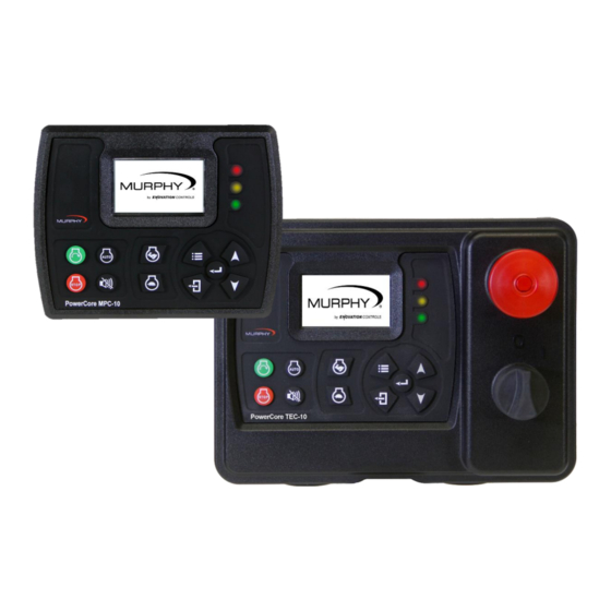
PowerCore
MPC-10 Engine Controller &
TEC-10 Panel
Operations Manual
support.enovationcontrols.com,
then search for MPC-10 or TEC-10.
®
00-02-0939
2019-06-13
Section 40
Advertisement
Table of Contents

Subscribe to Our Youtube Channel
Related Manuals for Enovation Controls Murphy PowerCore MPC-10


Summary of Contents for Enovation Controls Murphy PowerCore MPC-10
- Page 1 Software Release: [App: 02.09.10051.00; Config: 2.9.20024; Built in PowerVision Configuration Studio Version: 2.9.23042; BTL: 02.09.10015.00] ® PowerCore MPC-10 Engine Controller & TEC-10 Panel Operations Manual To see this manual in Spanish, German, French or Italian, please go to support.enovationcontrols.com, then search for MPC-10 or TEC-10. In order to consistently bring you the highest quality, full-featured products, we reserve the right to change our specifications and designs at any time.
- Page 2 Software Release: [App: 02.09.10051.00; Config: 2.9.20024; Built in PowerVision Configuration Studio Version: 2.9.23042; BTL: 02.09.10015.00] ENOVATION CONTROLS has made efforts to ensure the reliability of the MPC-10 / TEC-10 and to recommend safe use practices in system applications. Please note that in any application, operation and controller failures can occur.
- Page 3 Software Release: [App: 02.09.10051.00; Config: 2.9.20024; Built in PowerVision Configuration Studio Version: 2.9.23042; BTL: 02.09.10015.00] The MPC-10 can be set as an Auto-Start Controller. Please be cognizant at all times of hands and other objects that are in close proximity to the machine(s) being controlled as they may commence operation suddenly and without warning.
- Page 4 Software Release: [App: 02.09.10051.00; Config: 2.9.20024; Built in PowerVision Configuration Studio Version: 2.9.23042; BTL: 02.09.10015.00] - THIS PAGE INTENTIONALLY LEFT BLANK - Section 40 00-02-0939 2019-06-13...
-
Page 5: Table Of Contents
Software Release: [App: 02.09.10051.00; Config: 2.9.20024; Built in PowerVision Configuration Studio Version: 2.9.23042; BTL: 02.09.10015.00] Table of Contents Introduction ..........................7 Murphy PowerCore 10 (MPC-10 / TEC-10)..............7 User Interface .......................9 Accessing the Menu ........................ 10 Main Menu ..........................11 Auto Start/Stop Functions Defined..................16 Single Contact Start/Stop (commonly known as single float in pumping markets) .. - Page 6 Software Release: [App: 02.09.10051.00; Config: 2.9.20024; Built in PowerVision Configuration Studio Version: 2.9.23042; BTL: 02.09.10015.00] Advanced Engine Settings (Low Security) ..............32 Throttle Menu (Medium Security) ................36 Input / Output Menu ....................37 Application Configuration (Low Security) ..............40 Start / Stop Timers (Low Security) ................
-
Page 7: Introduction
Software Release: [App: 02.09.10051.00; Config: 2.9.20024; Built in PowerVision Configuration Studio Version: 2.9.23042; BTL: 02.09.10015.00] Introduction This document is designed to familiarize a user with the MPC-10 / TEC-10 and how to navigate the interface and modify the settings when setting up and operating the controller. The Quick Set Up guide assists with establishing the different functions in the MPC-10 / TEC-10 System Controller. - Page 8 Software Release: [App: 02.09.10051.00; Config: 2.9.20024; Built in PowerVision Configuration Studio Version: 2.9.23042; BTL: 02.09.10015.00] • ECU Stabilize Timer: This delay begins timing when the controller is powered up, in Spindown or when the Standby delays have expired. During this delay, the ECU-enabled output is turned on.
-
Page 9: User Interface
Software Release: [App: 02.09.10051.00; Config: 2.9.20024; Built in PowerVision Configuration Studio Version: 2.9.23042; BTL: 02.09.10015.00] User Interface The keypads on the MPC-10 / TEC-10 are comprised of 11 tactile buttons. This section describes the functions of each button. Figure 1: User Interface The buttons have the following functions: •... -
Page 10: Accessing The Menu
Software Release: [App: 02.09.10051.00; Config: 2.9.20024; Built in PowerVision Configuration Studio Version: 2.9.23042; BTL: 02.09.10015.00] The TEC-10 Panel offering also has a keyswitch and a stop button on the front: Figure 2: Panel stop button and on/off keyswitch Accessing the Menu The MPC-10 / TEC-10 have 3 menu security levels to restrict users from making changes after installation. -
Page 11: Main Menu
Software Release: [App: 02.09.10051.00; Config: 2.9.20024; Built in PowerVision Configuration Studio Version: 2.9.23042; BTL: 02.09.10015.00] The password will be entered left to right. Utilize the up and down arrows, and press the Enter button after each correct number: Entering this password will allow full access to the menu. If you enter the wrong password, it will reset the display to 0000, allowing you to restart the entering process. - Page 12 Relay [10A, Form C] • Digital Out [1A, B(+)] • Digital Out [1A, B(-)] NOTE: Although the functionality exists to set all analog and digital inputs to the same function, Enovation Controls strongly advises against this. Section 40 00-02-0939 2019-06-13...
- Page 13 Software Release: [App: 02.09.10051.00; Config: 2.9.20024; Built in PowerVision Configuration Studio Version: 2.9.23042; BTL: 02.09.10015.00] Application Configuration The Application Configuration menu is where an operator will set up the controller’s Auto Start Functions and Auto Throttling Methods, if the intended use is an auto start and/or auto throttling controller. Depending on which application is chosen in the menu, there are certain auto start functions and auto throttling methods hidden that are not pertinent to the application chosen.
- Page 14 Software Release: [App: 02.09.10051.00; Config: 2.9.20024; Built in PowerVision Configuration Studio Version: 2.9.23042; BTL: 02.09.10015.00] Hose Reel Irrigation The Hose Reel Irrigation application houses the auto start functions and auto throttle methods meant to be used on hose reel irrigation systems. The MPC-10 / TEC-10 allows for the hose reel pump to auto start with several methods, including the Local Start key which may be the most used in this application.
- Page 15 Software Release: [App: 02.09.10051.00; Config: 2.9.20024; Built in PowerVision Configuration Studio Version: 2.9.23042; BTL: 02.09.10015.00] Figure 6: Main Menu page 3 Start / Stop Timers The Start/Stop Timers menu provides the operator the ability to add a countdown timer, scheduled start/stop times, and an engine exercise timer.
-
Page 16: Auto Start/Stop Functions Defined
Software Release: [App: 02.09.10051.00; Config: 2.9.20024; Built in PowerVision Configuration Studio Version: 2.9.23042; BTL: 02.09.10015.00] Figure 7: Main Menu page 4 Load Configuration The Load Configuration menu is only available in the high security menu. This menu item allows the operator to choose a file to load onto the controller when a USB drive is attached to the programming harness of the controller. -
Page 17: Quick-Start Setup
Software Release: [App: 02.09.10051.00; Config: 2.9.20024; Built in PowerVision Configuration Studio Version: 2.9.23042; BTL: 02.09.10015.00] Quick-Start Setup The following sections provide a walk-through of the steps necessary for some of the various configurations and settings available on the MPC-10 / TEC-10 Controller. Cycling power to the controller is recommended after making changes to set points. -
Page 18: J1939 Electronic Engine Setup (Factory Default)
Software Release: [App: 02.09.10051.00; Config: 2.9.20024; Built in PowerVision Configuration Studio Version: 2.9.23042; BTL: 02.09.10015.00] J1939 Electronic Engine Setup (Factory Default) 1. Access Menu/Engine Settings/Engine Type to ensure J1939 is selected. 2. Press down arrow to Engine Manufacturer, select which engine manufacturer the controller is/will be used then press [Enter]. -
Page 19: Setting To Auto Start On Local Start Key
Software Release: [App: 02.09.10051.00; Config: 2.9.20024; Built in PowerVision Configuration Studio Version: 2.9.23042; BTL: 02.09.10015.00] Setting to Auto Start on Local Start Key 1. Access Menu/Application Configuration. Press the down arrow to Auto Start/Stop Function then press [Enter]. 2. Utilize the Up and Down arrows to select Local Start Key then press [Enter]. 3. -
Page 20: Setting Up To Auto Start On Level
Software Release: [App: 02.09.10051.00; Config: 2.9.20024; Built in PowerVision Configuration Studio Version: 2.9.23042; BTL: 02.09.10015.00] Setting up to Auto Start on Level 1. Access Menu/Application Configuration. Press the down arrow to Auto Start/Stop Function then press [Enter]. 2. Utilize the Up and Down arrows to select Level Transducer then press [Enter]. 3. -
Page 21: Setting Up To Stop The Engine From Utilizing The Countdown Timer
Software Release: [App: 02.09.10051.00; Config: 2.9.20024; Built in PowerVision Configuration Studio Version: 2.9.23042; BTL: 02.09.10015.00] 7. Assign 4-20mA, 0-5V Ambient Temperature or Model 12 as the function for the selected Analog Input. 8. Press [Back] once to return to the Analog Input menu. 9. -
Page 22: Additional Screens
Software Release: [App: 02.09.10051.00; Config: 2.9.20024; Built in PowerVision Configuration Studio Version: 2.9.23042; BTL: 02.09.10015.00] Additional Screens Figure 9: Main Screen This is the main screen, and it displays actual and target RPM, Mode of Operation, Timer progress, % Soot Level, % DEF Level and current State, along with icons and warnings. - Page 23 Software Release: [App: 02.09.10051.00; Config: 2.9.20024; Built in PowerVision Configuration Studio Version: 2.9.23042; BTL: 02.09.10015.00] Figure 12: Application Screen This screen displays the auto start/stop type and will also illustrate the throttling method for the auto start/stop. Figures 13: Regeneration Mode Screen & CAT/Perkins Regeneration Screen This is the Tier 4 Regeneration screen that is selected to be shown in the Tier 4 menu.
- Page 24 Software Release: [App: 02.09.10051.00; Config: 2.9.20024; Built in PowerVision Configuration Studio Version: 2.9.23042; BTL: 02.09.10015.00] Figure 15: Digital Output Status This screen will allow the operator to see what the digital output functions are set to without accessing the menu and the active setting which informs the user of the output status. Figure 16: Relay Status This screen will allow the operator to see what the relay status functions are set to without accessing the menu and the active setting which informs the user of the relay status.
-
Page 25: Iso Icons
Software Release: [App: 02.09.10051.00; Config: 2.9.20024; Built in PowerVision Configuration Studio Version: 2.9.23042; BTL: 02.09.10015.00] Figure 18: Analog Input Status This screen displays the Analog Input’s function selected in the menu for each input. Figure 19: Service Life Remaining Screens These two screens provide a list of service reminders and the hours left until the internal alarm will display the services needed. - Page 26 Software Release: [App: 02.09.10051.00; Config: 2.9.20024; Built in PowerVision Configuration Studio Version: 2.9.23042; BTL: 02.09.10015.00] Displays when the Engine ECU has inhibited a regeneration from occurring. This should also be shown when inhibiting regeneration selection is made in the menu. Displays when an emissions aftertreatment malfunction has occurred.
- Page 27 Software Release: [App: 02.09.10051.00; Config: 2.9.20024; Built in PowerVision Configuration Studio Version: 2.9.23042; BTL: 02.09.10015.00] JCB – DPF Emissions Filter Above 90%. Engine Overloaded JCB – DPF Emissions Filter at 100%. Engine Plugged JCB – Inducement Level 2,3 or Final. Displays when an active or unacknowledged warning fault exists.
-
Page 28: Icon Troubleshooting
Software Release: [App: 02.09.10051.00; Config: 2.9.20024; Built in PowerVision Configuration Studio Version: 2.9.23042; BTL: 02.09.10015.00] Suction Pressure Percent Load at Current RPM Current Engine Temperature Battery Voltage Icon Troubleshooting The warnings and shutdowns internally generated by the controller will show an Internal Fault on the top of the screen when a fault is displayed. - Page 29 Software Release: [App: 02.09.10051.00; Config: 2.9.20024; Built in PowerVision Configuration Studio Version: 2.9.23042; BTL: 02.09.10015.00] Brightness (Medium Security): allows the backlight of the screen to be adjusted. Factory set to 90. Parameter Setup (Low Security): allows four-up Page 1 and Page 2 parameters to be changed without using a PC.
- Page 30 Software Release: [App: 02.09.10051.00; Config: 2.9.20024; Built in PowerVision Configuration Studio Version: 2.9.23042; BTL: 02.09.10015.00] Manual Only (Medium Security): allows the operator to lock anyone out of placing the controller in Auto mode of operation. Factory set to Disable Power Up Auto/Manual (High Security): allows the controller to power up in either Manual or Auto Mode of operation depending on the selection chosen.
-
Page 31: Engine Settings (Low Security)
Software Release: [App: 02.09.10051.00; Config: 2.9.20024; Built in PowerVision Configuration Studio Version: 2.9.23042; BTL: 02.09.10015.00] controller will turn off the ECU enable output when a red lamp status is broadcast on the CANbus. Factory set to Controller & ECU. Engine Settings (Low Security) Engine Type (High Security): allows the selection between J1939 and Mechanical. -
Page 32: Advanced Engine Settings (Low Security)
Software Release: [App: 02.09.10051.00; Config: 2.9.20024; Built in PowerVision Configuration Studio Version: 2.9.23042; BTL: 02.09.10015.00] Warm Up Delay (Low Security): allows the operator to set the desired warm-up time/delay for the engine. This is the length of time the engine will run at a lower speed for its warm-up cycle. Factory set to 3 minutes Minimum Engine Speed (Medium Security): allows the setting of the lowest engine speed for continual operation. - Page 33 Software Release: [App: 02.09.10051.00; Config: 2.9.20024; Built in PowerVision Configuration Studio Version: 2.9.23042; BTL: 02.09.10015.00] Auto Stop Delay (Medium Security): this auto stop condition must remain active throughout this delay for an auto stop to occur. If the auto stop condition is removed during this delay, the delay is reset to zero.
- Page 34 Software Release: [App: 02.09.10051.00; Config: 2.9.20024; Built in PowerVision Configuration Studio Version: 2.9.23042; BTL: 02.09.10015.00] Post Warm-up Lockout 2 (Medium Security): Factory set to Disabled Post Warm-up Lockout 3 (Medium Security): Factory set to Disabled Post Warm-up Lockout 4 (High Security): Factory set to Disabled Post Warm-up Lockout 5 (High Security): Factory set to Disabled Bubble Lockout Setup (Medium Security): this is a setup for a delay that begins timing when the selected functions are active.
- Page 35 Software Release: [App: 02.09.10051.00; Config: 2.9.20024; Built in PowerVision Configuration Studio Version: 2.9.23042; BTL: 02.09.10015.00] Underspeed Shutdown (Medium Security): a shutdown will occur when the engine speed reaches this set point. Factory set to 0 RPM Overspeed Shutdown (Medium Security): a shutdown will occur when the engine speed reaches this set point.
-
Page 36: Throttle Menu (Medium Security)
Software Release: [App: 02.09.10051.00; Config: 2.9.20024; Built in PowerVision Configuration Studio Version: 2.9.23042; BTL: 02.09.10015.00] Low Suction Pressure Shutdown (Medium Security): a shutdown will occur when the pressure reaches this set point. Menu setting shown after analog input is set. Factory set to 0 High Gearbox Pressure Warning (Medium Security): an alarm will occur when the pressure reaches this set point. -
Page 37: Input / Output Menu
Software Release: [App: 02.09.10051.00; Config: 2.9.20024; Built in PowerVision Configuration Studio Version: 2.9.23042; BTL: 02.09.10015.00] Separate TSC1 Source Address (High Security): allows the user to set a separate source address for TSC1 throttling from the controller’s claim address. This should only be done if the service technician knows this to be true. - Page 38 Software Release: [App: 02.09.10051.00; Config: 2.9.20024; Built in PowerVision Configuration Studio Version: 2.9.23042; BTL: 02.09.10015.00] Digital Input 2 (Medium Security): Factory set to Function: Auto Start Maintained, Active: B-, Action: Not Used Digital Input 3 (Medium Security): Factory set to Function: Auto Stop Maintained, Active: B-, Action: Not Used Digital Input 4 (Medium Security): Factory set to Function: Low Coolant Level, Active: B-, Action: Shutdown...
- Page 39 Software Release: [App: 02.09.10051.00; Config: 2.9.20024; Built in PowerVision Configuration Studio Version: 2.9.23042; BTL: 02.09.10015.00] acknowledgement of the fault is NOT required to restart in Auto after shutdown occurs if active shutdown is removed from controller) Analog Inputs (1-3) (Medium Security): for each of the analog inputs, the ability to select the following parameters exists: Analog input 1 (Medium Security): Factory set to Function: Disabled Analog Input 2 (Medium Security): Factory set to Function: Disabled...
-
Page 40: Application Configuration (Low Security)
Software Release: [App: 02.09.10051.00; Config: 2.9.20024; Built in PowerVision Configuration Studio Version: 2.9.23042; BTL: 02.09.10015.00] Relay 1 (Medium Security): Factory set to Crank, Starter Relay Relay 2 (Medium Security): Factory set to ECU Enable Relay 3 (Medium Security): Factory set to Not Used DO1 (B+, 1A) (Medium Security): Factory set to Not in Auto DO2 (B+, 1A) (Medium Security): Factory set to Engine Running DO3 (B-, 1A) (Medium Security): Factory set to Throttle Decrease... - Page 41 Software Release: [App: 02.09.10051.00; Config: 2.9.20024; Built in PowerVision Configuration Studio Version: 2.9.23042; BTL: 02.09.10015.00] allows for pumps of many variations to be used in a manual/auto start environment utilizing the more common auto start and throttling functions. Air Compressor: The Air Compressor application houses the auto start functions and auto throttle methods meant to be used on most engine-driven air compressor applications.
- Page 42 Software Release: [App: 02.09.10051.00; Config: 2.9.20024; Built in PowerVision Configuration Studio Version: 2.9.23042; BTL: 02.09.10015.00] detail the method of tuning the proportional-integral-derivative control loop commonly used in PLC programming language. NOTE: When selecting PID Auto Throttle as the auto throttle type the Ramp Inc Rate and Ramp Dec Rate in the Throttle menu should be set to 0 RPM per Second so the PID does not combat the ramp rates set in the controller.
- Page 43 Software Release: [App: 02.09.10051.00; Config: 2.9.20024; Built in PowerVision Configuration Studio Version: 2.9.23042; BTL: 02.09.10015.00] Maintain Pressure (Medium Security): This selection is present when selecting Pressure Transducer as the Auto Throttling Method. The engine will be throttled between the min. and max. RPM set points to maintain this pressure.
- Page 44 Software Release: [App: 02.09.10051.00; Config: 2.9.20024; Built in PowerVision Configuration Studio Version: 2.9.23042; BTL: 02.09.10015.00] Pressure D (High Security): This selection is present when PID Auto Throttle Type selected and allows adjustment of the Derivative setting of the PID loop when throttling. Factory set to 0.001 Level Transducer (Medium Security): This selection is only present when selecting Level Transducer in the Auto Start / Stop Function or Auto Throttle Method.
- Page 45 Software Release: [App: 02.09.10051.00; Config: 2.9.20024; Built in PowerVision Configuration Studio Version: 2.9.23042; BTL: 02.09.10015.00] Stop Temperature (Medium Security): When the temperature rises to this set point, an auto stop will occur. Factory set to 32 F. Engage RPM. In the Chipper Auto mode, the engine speed when the Feed Engage output will be activated. Factory set to 2200 RPM.
-
Page 46: Start / Stop Timers (Low Security)
Software Release: [App: 02.09.10051.00; Config: 2.9.20024; Built in PowerVision Configuration Studio Version: 2.9.23042; BTL: 02.09.10015.00] Chipper type: DUMPING: CHIPPER AUTO MODE 1. (2) Control outputs, Engage and Disengage are off prior to start up. 2. The engine is started manually using the MPC-10 / TEC-10 and throttled manually up to the Engage RPM set point: 3. - Page 47 Software Release: [App: 02.09.10051.00; Config: 2.9.20024; Built in PowerVision Configuration Studio Version: 2.9.23042; BTL: 02.09.10015.00] time unmonitored and then shut itself off when that time has expired or when a local key stop occurs. Format of HH:MM:SS. Maximum countdown time is 120 hours. Factory set to 00:00:00 NOTE: The countdown timer is only active when starting in Auto mode.
-
Page 48: Communication (High Security)
Software Release: [App: 02.09.10051.00; Config: 2.9.20024; Built in PowerVision Configuration Studio Version: 2.9.23042; BTL: 02.09.10015.00] Exercise Running Loaded Time (Medium Security): Time the operator sets for the engine to run if voltage drops below the low voltage set point. Factory set to 15 minutes Communication (High Security) Communication Type (High Security): PVA Gauge: this function will be used if utilizing PVA Gauges on the RS485 Communications... -
Page 49: Passcodes (High Security)
Software Release: [App: 02.09.10051.00; Config: 2.9.20024; Built in PowerVision Configuration Studio Version: 2.9.23042; BTL: 02.09.10015.00] Passcodes (High Security) This menu allows the operator using the High Security passcode to see the three 4-digit passcodes for Low, Medium and High security. This is a visual menu only. The security passcodes are only able to be altered via PowerVision for Controllers PC tool. -
Page 50: Communication Mapping
Software Release: [App: 02.09.10051.00; Config: 2.9.20024; Built in PowerVision Configuration Studio Version: 2.9.23042; BTL: 02.09.10015.00] Communication Mapping This section outlines the RS485 Modbus Register Map and CAN Parameter Map. MPC-10 & TEC-10 RS485 Modbus Registers NOTE: The registers labeled Read/Write will allow the operator to change values through the Modbus as a temporary modification. - Page 51 Software Release: [App: 02.09.10051.00; Config: 2.9.20024; Built in PowerVision Configuration Studio Version: 2.9.23042; BTL: 02.09.10015.00] 13 = Reserved Reserved 14 = Reserved Reserved 15 = Remote Stop SD (0 or 1) 40009 Read Only Active Shutdown Status (Active Fault: Bit = 1, Inactive: Bit = 0) 0 = Coolant Level SD (0 or 1) 1 = High Level SD...
- Page 52 Software Release: [App: 02.09.10051.00; Config: 2.9.20024; Built in PowerVision Configuration Studio Version: 2.9.23042; BTL: 02.09.10015.00] 40020 Read Only J1939.Actual Engine Torque Percent 40021 Read Only Reserved Reserved 40022 Read Only J1939.Diesel Particulate Filter Outlet Temperature Celsius 40023 Read Only J1939.Diesel Particulate Filter Intake Temperature Celsius 40024 Read Only...
- Page 53 Software Release: [App: 02.09.10051.00; Config: 2.9.20024; Built in PowerVision Configuration Studio Version: 2.9.23042; BTL: 02.09.10015.00] 1 = Reserved Reserved 2 = Reserved Reserved 3 = Reserved Reserved 4 = Reserved Reserved 5 = Reserved Reserved 6 = Reserved Reserved 7 = Reserved Reserved 8 = Reserved Reserved...
- Page 54 Software Release: [App: 02.09.10051.00; Config: 2.9.20024; Built in PowerVision Configuration Studio Version: 2.9.23042; BTL: 02.09.10015.00] 40241 Read Only Modbus EEPROM Values Saved Confirmation (0 or 1) (Saved = 1) 40242 Read Only Active Warning Status (Active Fault: Bit = 1, Inactive: Bit = 0) 0 = Low Fuel Warn (0 or 1) 1 = Fuel Leak Warn...
-
Page 55: Can Parameter Map
Software Release: [App: 02.09.10051.00; Config: 2.9.20024; Built in PowerVision Configuration Studio Version: 2.9.23042; BTL: 02.09.10015.00] 11 = Reserved Reserved 12 = Reserved Reserved 13 = Reserved Reserved 14 = Reserved Reserved 15 = Reserved Reserved 40245-40246 Read Only J1939.Aftertreatment 1 Diesel Particulate Filter Time to Next Seconds Active Regeneration 40247... - Page 56 Software Release: [App: 02.09.10051.00; Config: 2.9.20024; Built in PowerVision Configuration Studio Version: 2.9.23042; BTL: 02.09.10015.00] 5 = Check Safe to Start 6 = Prestart 2 Delay 7 = Crank 8 = Crank Rest 9 = False Start Check 10 = Engine Warmup 11 = Line Fill 1 12 = Line Fill 2 13 = Running Loaded...
- Page 57 Software Release: [App: 02.09.10051.00; Config: 2.9.20024; Built in PowerVision Configuration Studio Version: 2.9.23042; BTL: 02.09.10015.00] Read Only Low Coolant Level Warn (0 or 1) Read Only Water in Fuel Warn (0 or 1) Read Only No Flow Warn (0 or 1) Read Only High Engine Oil Temp Warn (0 or 1)
- Page 58 Software Release: [App: 02.09.10051.00; Config: 2.9.20024; Built in PowerVision Configuration Studio Version: 2.9.23042; BTL: 02.09.10015.00] Read Only Low Level SD (0 or 1) Read Only High Flow SD (0 or 1) Read Only Low Flow SD (0 or 1) Reserved Reserved Reserved Reserved...
-
Page 59: Supplementary Information
. PowerVision allows engineering the ability to deliver quicker software updates with the flexibility of a software developer’s environment. The addition of PowerVision gives Enovation Controls the ability to provide a free-of-charge basic PC configuration program (PowerVision for Controllers) to all customers for changing default parameters within the controller. - Page 60 Software Release: [App: 02.09.10051.00; Config: 2.9.20024; Built in PowerVision Configuration Studio Version: 2.9.23042; BTL: 02.09.10015.00] allows custom software changes to almost all aspects of the controller from languages, screen layouts, text strings, Modbus communications, CAN communications, IO, faults, state machines, activity diagrams (visual scripting), and menu building to name a few.
-
Page 61: Mpc-10 Specifications
Software Release: [App: 02.09.10051.00; Config: 2.9.20024; Built in PowerVision Configuration Studio Version: 2.9.23042; BTL: 02.09.10015.00] MPC-10 Specifications Interface Display: Monochrome HR-TFT, 2.7 in. / 68mm, WQVGA (400 x 240 pixels) (3) LEDs: green (mode), yellow (warning) and red (shutdown) Operator controls: (11) Raised silicon keypads, tactile feedback Power Supply Operating Voltage: 8-32 VDC, reverse battery polarity and load-dump protected... -
Page 62: Tec-10 Specifications
Software Release: [App: 02.09.10051.00; Config: 2.9.20024; Built in PowerVision Configuration Studio Version: 2.9.23042; BTL: 02.09.10015.00] TEC-10 Specifications Interface Display: Monochrome HR-TFT, 2.7 in. / 68mm, WQVGA (400 x 240 pixels) (3) LEDs: green (mode), yellow (warning) and red (shutdown) Operator controls: (11) Raised silicon keypads, tactile feedback (1) Keyed Rotary switch, power on/off (1) Push-switch (red), engine stop... - Page 63 Software Release: [App: 02.09.10051.00; Config: 2.9.20024; Built in PowerVision Configuration Studio Version: 2.9.23042; BTL: 02.09.10015.00] THIS PAGE INTENTIONALLY LEFT BLANK Section 40 00-02-0939 2019-06-13...
- Page 64 Software Release: [App: 02.09.10051.00; Config: 2.9.20024; Built in PowerVision Configuration Studio Version: 2.9.23042; BTL: 02.09.10015.00] THIS PAGE INTENTIONALLY LEFT BLANK...
- Page 65 Software Release: [App: 02.09.10051.00; Config: 2.9.20024; Built in PowerVision Configuration Studio Version: 2.9.23042; BTL: 02.09.10015.00]...
Need help?
Do you have a question about the Murphy PowerCore MPC-10 and is the answer not in the manual?
Questions and answers