Table of Contents
Advertisement
Quick Links
AW216TS Code 107712
AW254TS Code 107713
Original Instructions
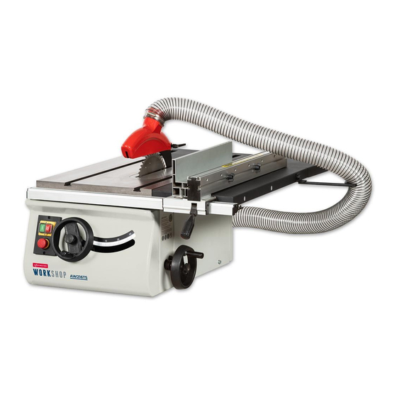
AW216TS & AW254TS
216mm & 254mm Table Saw
Code: 107712 AW216TS
Code: 107713 AW254TS
Floor Stand
Cabinet Stand
Left Hand Extension Table
Sliding Table Kit
Code: 104931 for AW216TS
Code: 104932 for AW216TS
Code: 106808 for AW216TS
Code: 104930 for AW216TS
Code: 106804 for AW254TS
Code: 106806 for AW254TS
Code: 106809 for AW254TS
Code: 106805 for AW254TS
AT: 11/02/2022
BOOK VERSION: 6
Advertisement
Table of Contents

Subscribe to Our Youtube Channel
Related Manuals for Axminster WORKSHOP AW216TS


Summary of Contents for Axminster WORKSHOP AW216TS
- Page 1 AW216TS Code 107712 AW254TS Code 107713 Original Instructions AW216TS & AW254TS 216mm & 254mm Table Saw Code: 107712 AW216TS Code: 107713 AW254TS Floor Stand Cabinet Stand Left Hand Extension Table Sliding Table Kit Code: 104931 for AW216TS Code: 104932 for AW216TS Code: 106808 for AW216TS Code: 104930 for AW216TS Code: 106804 for AW254TS...
- Page 2 Exploded Diagrams/Lists 29-30-31-32-33-34-35-36-38-7-38 Wiring Diagram Cert No: MJ2320,MJ2325R, EU Declaration of Conformity MJ2325G-2, MJ2331-2, MJ2330 This machine complies with the following directives: Axminster tool Centre Ltd Axminster Devon EX13 5PH UK 2006/42/EC axminstertools.com EN 1870-19:2013 declares that the machinery described:-...
-
Page 3: What's Included
WHAT’S INCLUDED Quantity Item Part Model Number AW216TS, AW254TS Basic Table Saw Outer Flexible Hose Side Extension Table Hose Clips Rear Extension Table Push Stick Operating Wheels with Clamping Knobs Blade Locking Bar Rip Fence Assembly 24mm Spanner Rip Fence Extension 13-15mm Spanner Rip Fence Rail with Scale Hex Keys 6,5,3,2mm... -
Page 4: Optional Accessories
OPTIONAL ACCESSORIES Code 104931 Floor Stand Assembly Quantity Item Part Leg Brackets Long Upper Support Struts Short Upper Support Struts Long Lower Support Struts Short Lower Support Struts Threaded Rubber Feet Floor Stand Bag of Fixings Code 104932 Cabinet Stand Assembly Quantity Item Part... - Page 5 OPTIONAL ACCESSORIES Code 104930 Sliding Table Kit (AW216TS) Code 106805 Sliding Table Kit (AW254TS) Quantity Item Part Quantity Item Part Sliding Carriage Support Bracket Sliding Carriage Support Bracket Threaded Adjuster Assembly Threaded Adjuster Assembly Height Adjusting Blocks Height Adjusting Blocks Hex Key Hex Key Fence Mitre Casting with Lift &...
-
Page 6: General Instructions For 230V Machines
OPTIONAL ACCESSORIES Quantity Item Part Table Insert for the AW216TS Code: 104933 Table Insert for the AW254TS Code: 106807 19mm Mitre Fence Left Hand Extension Table with Long Rip Fence Rail/Scale AW216TS Code: 106808 Left Hand Extension Table with Long Rip Fence Rail/Scale AW254TS Code: 106809 GENERAL INSTRUCTIONS FOR 230V MACHINES The following will enable you to observe good working •... - Page 7 SPECIFIC INSTRUCTIONS FOR TABLE SAWS Make sure the saw blade is the correct type for the job in hand. After switching off, never try to slow the saw down more Do not force the saw, if the saw begins to ‘stall’ you are ‘forcing quickly by applying side pressure (with a piece of wood?) to the cut’...
-
Page 8: Specification
SPECIFICATION Code 107712 Code 107713 Model AW216TS Model AW254TS Rating Workshop Rating Workshop Power 1.1 kW 50Hz 230V 1ph Power 1.5 kW 50Hz 230V 1ph Blade Dia/Bore 216 mm / 30 mm Blade Dia/Bore 254 mm / 30 mm Blade Tilt 0°... - Page 9 ASSEMBLY Fig 06-07 Fig 10-11-12 3. Locate the inner flexible hose (V) and two hose clips (M). Place a clip over each end of the hose and secure the hose over the extraction outlets, see fig 06-07. Fig 08 Fig 13-14-15 Line up the holes 4.
- Page 10 ASSEMBLY Fig 16-17 Clamping knob Levelling grub screws Insert plate 7. Raise the saw by first releasing the rise & fall operating wheel clamping knob, remove the five cross head screws 9. Locate the crown guard (K), flexible hose (L) and hose holding the table insert and place safely aside, see 16-17.
- Page 11 ASSEMBLY Fig 35 Fig 38-39-40 11. Put to hand four M8 Bolts with washer/nuts (U) and rip fence rail with scale (G). Insert two bolts with washers up through the holes to the underside end of the side extension ‘T’ Slot table (B) and lightly screw on two bolts.
- Page 12 ASSEMBLY 107712-107713 Basic Saw Step 4 Mounting the Stand to the Saw Remove the rip fence, crown guard and hose and lower saw AW216TS Table Saw assembled for work bench set up blade below the table. With assistance turn the saw assembly (A) over &...
- Page 13 ASSEMBLY 104932 Optional Cabinet Stand for AW216TS Step 5 106806 Optional Cabinet Stand for AW254TS Locate all the components for the cabinet stand as shown on page 04-05 and follow the instructions below. Step 1 Mounting the Cabinet to the Saw Turn the saw assembly (A) over, place the base plate (W) on top and align the holes as shown in step 6.
- Page 14 ASSEMBLY 104930 Optional Sliding Table Kit for AW216TS Fig 45-46-47 106805 Optional Sliding Table Kit for AW254TS Washer 1. Locate the carriage support brackets (20). Cap head bolt Offer up the elongated slots in both support brackets with the threaded holes in the side of the saw assembly (A).
- Page 15 ASSEMBLY Fig 50-51-52 Fig 54-55-56-57 PULL Table stop pin knob Pivot Self tapping screws Locking nuts 6. Place a level across both tables, using the supplied hex key 4. Locate the sliding table (28), turn the table over and pull (R) adjust both height adjusting blocks (22) and the threaded out and twist the table stop pin knob so it’s in the unlocked adjusters on each support bracket (20), until the sliding table...
- Page 16 ASSEMBLY Fig 59 Fig 62 9. Remove the washer/nut from the tool post (25), insert the post down through the machined holes in both mitre casting (24) and sliding table (28) and secure using the washer/nut, see fig 62. 10. Loosen the hold down clamping knob (26) and slide the assembly down the tool post (25) and clamp in position, see fig 63.
- Page 17 ASSEMBLY 90˚ Stop 14. Using a 90˚ square check that the blade is at 90˚ to the fence assembly (29) and make adjustments until correct, see fig 70. Fig 70 Butterfly knob 12. Slide the fence (29) near the blade but not touching, tighten the butterfly knobs, see fig 66-67.
-
Page 18: Illustration And Parts Description
ILLUSTRATION AND PARTS DESCRIPTION Code 107712 Basic Table Saw Code 107713 Basic Table Saw Crown guard Flexible hose Riving knife Rear extension table Saw blade Rip fence rail Rip fence clamping handle Saw assembly access panel 45˚ Scale NVR Control panel Main Table Saw Rip fence extension Rip fence... - Page 19 ILLUSTRATION AND PARTS DESCRIPTION ON/OFF control switch (A), Emergency stop button (B) Optional 104928 Mitre Fence Rise and Fall operating wheel (C) Tilt scale pointer and adjusting screw 100mm Dust extraction moulding Rip fence magnifying glass and index marker Motor and saw assembly Optional 104933 insert gives better material support for cutting thin strips...
- Page 20 ILLUSTRATION AND PARTS DESCRIPTION Table Saw Optional Accessories Code 104931 AW216TS Floor Stand Code 106804 AW254TS Floor Stand Code 106808 AW216TS Left Hand Extension Table Code 106809 AW254TS Left Hand Extension Table Code 104932 AW216TS Cabinet Stand Code 104930 AW216TS Sliding Table Code 106806 AW254TS Cabinet Stand Code 106805 AW254TS Sliding Table...
- Page 21 ILLUSTRATION AND PARTS DESCRIPTION Cabinet stand storage door Distance stop (27) with micro adjusting wheel (a) Fence mitre scale, pointer Fence mitre adjusting screw stops for -45˚ to +45˚ and clamping handle Table stop pin knob, engage to Hold down clamp assembly Sliding carriage stop, prevent the table from sliding prevents the sliding table...
-
Page 22: Setup And Adjustment
SET UP AND ADJUSTMENT The Riving Knife Setting the Rip Fence & Scale 1. Raise the saw blade to its highest point and remove the saw MAKESURE THE BLADE IS SQUARE TO THE blade crown guard (K) and the table insert, place safely aside, TABLE AND THE FENCE IS SQUARE TO THE see fig 71-72. - Page 23 SET UP AND ADJUSTMENT Fig 78 Pointer position pencil mark 3. Place the fence assembly up against the blade and lock in place, see fig 78. 4. Using a pencil draw a line on the fence rail to mark the postion, see fig 79.
- Page 24 SET UP AND ADJUSTMENT Magnifing Class Pointer set to ‘ZERO’ ‘Zero’ pointer 7. Trim any excess material from the end of the fence rail, see fig 85. Fig 85 Rip Fence Extension The rip fence extension can be repositioned from the vertical to a horizontal position for guiding thin pieces through.
- Page 25 SET UP AND ADJUSTMENT Saw pivot scale 45˚ Adjusting the Cutting Height Release the clamping knob, adjust the blade height with the rise and fall operating wheel, see fig 91, so that the blade teeth are protruding through the work piece. Fig 91 Clamping knob Adjusting the Pivot...
- Page 26 OPERATING INSTRUCTIONS NOTE: BEFORE USING YOUR SAW, GO ROUND AND MAKE SURE EVERYTHING IS SECURE, FASTENED DOWN, THAT ALL TOOLS ARE CLEARED AWAY FROM THE WORK AREA! NOTE: Secure larger pieces of timber to the table by using the hold down clamp. CHECK: THE BLADE FOR SHARPNESS, MISSING TEETH, RESIN BUILD UP ETC., Cutting Narrow Pieces...
-
Page 27: Changing The Saw Blade
CHANGING THE SAW BLADE Fig 105-106-107-108 DISCONNECT THE MACHINE FROM THE MAINS SUPPLY! 1. Raise the saw blade to its highest point, remove the saw blade crown guard, remove the five cross head screws that secure the table insert, place carefully aside and remove the table insert, see fig 101-102. -
Page 28: Maintenance
MAINTENANCE Fig 109-110 1. Keep the saw as clean and free from saw dust build up as is practical. Periodically, remove the saw gullet by removing the side access panel to the side of the machine and undo the two Hex screws on either side of the gullet, see fig 109-110. - Page 29 EXPLODED DIAGRAMS/LISTS 107712 AW216TS Basic Table Saw Diagram A Continues over...
- Page 30 EXPLODED DIAGRAMS/LISTS 107712 AW216TS Basic Table Saw Diagram A Description Front Rail Rip Fence Adjusting Thread Rod Right End Captor Front Rail Eccentric Wheel Locking Knob Left End Captor Front Rail Locking Shaft Semi-circle key 3x16 Taping Screw ST4.2 x 10 Locking Knob Angel Connection Knob Hex.Bolt M8 x 16...
- Page 31 EXPLODED DIAGRAMS/LISTS 104930 AW216TS Optional Sliding Table Kit Diagram B Continues over...
- Page 32 EXPLODED DIAGRAMS/LISTS 104930 AW216TS Optional Sliding Table Kit Diagram B Description Washer 12mm Mounting Bracket Cir-Clips for Shaft 12mm Mitre Guage Stud Hold Down Scale Mount Disc Hold Down Wing Nut Spring Hold Down Bolt Guide Hex.Nut M12 Locating Bracket Hex.
- Page 33 EXPLODED DIAGRAMS/LISTS 104932 AW216TS Optional Cabinet Stand Diagram C Description Washer 8mm Right Panel,Cabinet Stand Hex.Nut M8 Left Panel, Cabinet Stand Spring Washer 8 Rear Panel,Cabinet Stand Cross Recessed Pan Head Screw M6 x 12 Sidelong Support Front Panel Access Door, Cabinet Stand Ratchet Lever Hex.
- Page 34 EXPLODED DIAGRAMS/LISTS 107713 AW254TS Basic Table Saw Diagram A...
- Page 35 EXPLODED DIAGRAMS/LISTS 107713 AW254TS Basic Table Saw Diagram A Description Bottom Panel Hex.Bolt M8 x 20 Motor Pulley Switch Hex.Nut M10 Pulley Pointer Block Levelling Foot Motor Washer 6mm Cross Recessed Pan Head Screw M6 x 12 Shaft Base Blade Guard Front Rail Saw Blade Sleeve Riving Knife...
- Page 36 EXPLODED DIAGRAMS/LISTS 106805 AW254TS Optional Sliding Table Kit Diagram B...
- Page 37 EXPLODED DIAGRAMS/LISTS 106805 AW254TS Optional Sliding Table Kit Diagram B Description Disc Hold Down Mitre Gauge Spring Hold Down Scale Mount Hex.Nut M12 Wing Nut Hex. Socket Cap Head Bolt M5 x 12 Bolt Guide Washer 5mm Locating Bracket Star-Type Knob Hold Down Locating Plate Ratchet Lever Scale...
- Page 38 EXPLODED DIAGRAMS/LISTS 106806 AW254TS Optional Floor Stand Diagram C Description Stand Leg Upper Long Bracket Stand Leg Upper Short Bracket Stand Leg Lower Long Bracket Stand Leg Lower Short Bracket Stand Leg Levelling Foot Hex.Nut M8 Washer 8mm Hex.Bolt M8 x 16 106806 AW254TS Optional Cabinet Stand Diagram D Description Access Door Cabinet Stand...
-
Page 39: Wiring Diagram
WIRING DIAGRAM... - Page 40 The packaging is suitable for recycling. Please dispose of it in a responsible manner. EU Countries Only Do not dispose of electric tools together with household waste material. By law they must be collected and recycled separately. Axminster Tools, Axminster Devon EX13 5PH axminstertools.com...
Need help?
Do you have a question about the WORKSHOP AW216TS and is the answer not in the manual?
Questions and answers