
Related Manuals for Axminster 250mm Slide Mitre Saw


Summary of Contents for Axminster 250mm Slide Mitre Saw
- Page 1 Mitre Saw Class 2 Laser Power output<1mW A X M I N S T E R W H I T E Axminster Reference No:AWSMS102 w w w. a x m i n s t e r. c o . u k...
-
Page 2: Table Of Contents
Index of Contents... Page No. Index of Contents........................01 Declaration of Conformity………….………..……..………….........02 What’s in the Box………….………..……..…………............03 Specifications….………..……..………….................03 Table of Capacities....................04 General Instructions for 230V Machines..........05-06-07-08 General Safety Precautions for Mitre Saws...........06-07-08 Initial Setup.......................09 Illustration, Identification and Parts Description........10-11-12-13-14 Adjusting the Saw...................14-15-16 Operation of the Laser..................... -
Page 3: Declaration Of Conformity
Declaration of Conformity... A X M I N S T E R W H I T E Copied from CE Certificate The undersigned, K. Bodenstein authorised by Jiangsu Jinfeida Power Tools Co., Ltd. Xiejia Town, Gaoyou Jiangsu 225644 P.R. China declares that this product: Mitre Saw MJ2625III, MJ2625IIIA... -
Page 4: What's In The Box
1 No: Cut length stop 1 No: Saw Dust collection bag 1 No: Instruction Manual 1 No: Guarantee Card Specification Axminster No. 210036 (AWSMS102) Rated: Light Trade Motor: 230V 50Hz Single Phase 1,800W Blade Dia/Bore 250mm Bore 30mm Speed: 4500rpm Laser Class2 Laser Output <1mW... -
Page 5: Table Of Capacities
Table of Capacities... A X M I N S T E R W H I T E Always use (250mm) saw blades with a rated speed in excess of 4,500 r.p.m. The machine is supplied with a 250mm GP (40 tooth) Saw blade, with a 30mm bore for cutting TIMBER. For precision trimming e.g. -
Page 6: General Instructions For 230V Machines
General Instructions for 230V Machines... A X M I N S T E R W H I T E Good Working Practices/Safety The following suggestions will enable you to observe good working practices, keep yourself and fellow workers safe and maintain your tools and equipment in good working order. -
Page 7: General Safety Precautions For Mitre Saws
General Instructions for 230V Machines... A X M I N S T E R W H I T E UNDER NO CIRCUMSTANCES SHOULD WARNING!! CHILDREN BE ALLOWED IN WORK AREAS Once the saw is mounted, carry out any setting operations, (mitre, tilt..?), and remove all tools used in the setting operations (if any) and place safely out of the way. - Page 8 General Safety Precautions for Mitre Saw... A X M I N S T E R W H I T E DO NOT change blades with power connected. Always use the correct accessories; especially the correctly sized spanner on the arbor bolt, DO NOT risk damaging the saw by using incorrectly fitting accessories.
- Page 9 General Safety Precautions for Mitre Saw... A X M I N S T E R W H I T E DO NOT allow the saw to 'stall'; if unfortunate circumstances cause the machine to stall, switch off immediately, disconnect the machine and clear the 'jam' by hand. DO NOT attempt to re-start the machine until the 'jam' is cleared.
-
Page 10: Initial Setup
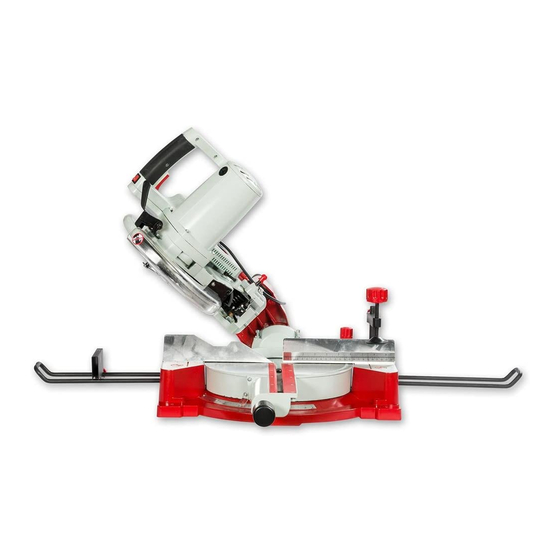
Initial Set Up... A X M I N S T E R Rubber foot W H I T E Lift the saw clear of the box using the two hand grips moulded into the sides of the chassis, and set on a clear flat surface, taking care not to trap or pinch the power cable under the chassis. - Page 11 Illustration & Description... A X M I N S T E R Saw arbor lock button Guard latch W H I T E Laser switch Tilt preset stop Upper guard Dust bag Motor brush inspection port Hold down clamp Fence Main Saw Chassis Extension/ support frames...
- Page 12 Identification & Parts Description... A X M I N S T E R W H I T E Your 250mm sliding arm compound mitre saw will have been shipped to you in the ‘housed’ position, i.e. with the saw body locked down. Please take some time to identify the various parts of your machine so that you are familiar with the terminology we will use to enable you to set up and operate your machine safely and correctly.
- Page 13 Illustration & Description... A X M I N S T E R W H I T E Adjustable depth stop Upper guard Operating handle Trigger switch Lock down pin Lower guard Handle Motor/vents Sliding arm Saw body frame locking clamp Turn table locking clamp Tilt housing Tilt preset stop...
- Page 14 Identification & Parts Description... A X M I N S T E R W H I T E Turntable Mounted into a circular recess in the main saw chassis, the turntable also mounts the extrusion that contains the kerf plate (the plate with the slot that allows the saw to enter the table) The locking clamp for the turntable is mounted on the right hand side of the chassis behind the fence.
-
Page 15: Adjusting The Saw
Identification & Parts Description... A X M I N S T E R Fence This is an aluminium casting bolted to the rear of the saw table. It has W H I T E various cut-outs and shapes machined and moulded into it to allow the mitre, tilt or compound cuts to be made. - Page 16 Adjusting the Saw... A X M I N S T E R W H I T E Perpendicular (Square) Adjustment Continued Mitre Scale Pointer Fig Ea 0˚ degrees Fig E Engineers square Locate and loosen the 4 bolts that hold the fence to the chassis. Adjust as necessary until the fence is square to the blade.
- Page 17 Adjusting the Saw... A X M I N S T E R W H I T E Fig G Fig H Tilt preset stop Tilt clamping lever Engineers square Fig I Tilt pointer 0˚ degrees Fig J 45˚degrees Mitre Saw at 45˚ degrees...
-
Page 18: Operation Of The Laser
The position of the laser can be adjusted to align the beam precisely with the saw blade. There are no serviceable parts in the laser so if a problem occurs you will need to contact Axminster Power Tool Centre Customer Services Department. 0800 371822 Setting the Laser... - Page 19 Setting the Laser... A X M I N S T E R W H I T E Laser toggle switch Fig K Fig P Fig O To adjust the laser, loosen the To adjust the mounting bracket caphead screw on the holder loosen the caphead bolt...
-
Page 20: Changing The Saw Blade
Changing the Saw Blade... A X M I N S T E R W H I T E DISCONNECT THE SAW FROM THE MAINS SUPPLY 1. Locate the two screws as indecated holding the front of the saw guard bracket, and loosen and remove them to allow the saw guard bracket to pivot on the rear screw. -
Page 21: Changing The Saw Blade
Changing the Saw Blade... A X M I N S T E R W H I T E Fig S Fig Sa Saw arbor 13mm lock button Spanner Engage the saw arbor lock and fit the spanner onto the bolt, keeping the lock depressed, loosen the saw arbor bolt by turning clockwise, (left hand thread). -
Page 22: Parts Breakdown/List
Parts Breakdown... A X M I N S T E R W H I T E... - Page 23 Parts Breakdown... A X M I N S T E R W H I T E...
- Page 24 Parts List... A X M I N S T E R W H I T E...
- Page 25 Parts List... A X M I N S T E R W H I T E...
- Page 26 Parts List... A X M I N S T E R W H I T E...
-
Page 27: Notes
Notes... A X M I N S T E R W H I T E... - Page 28 Class 2 Laser Axminster Reference No:AWSMS102 Power output<1mW A X M I N S T E R Axminster Devon EX13 5PH UK W H I T E FREEPHONE 0800 371822 www.axminster.co.uk...
Need help?
Do you have a question about the 250mm Slide Mitre Saw and is the answer not in the manual?
Questions and answers