Sign In
Upload
Download
Table of Contents
Contents
Add to my manuals
Delete from my manuals
Share
URL of this page:
HTML Link:
Bookmark this page
Add
Manual will be automatically added to "My Manuals"
Print this page
×
Bookmark added
×
Added to my manuals
Manuals
Brands
Axminster Manuals
Saw
AWHBS350N
User manual
Axminster AWHBS350N User Manual
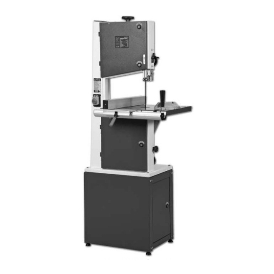
Floor standing bandsaw
Hide thumbs
Also See for AWHBS350N
:
Instructions manual
(33 pages)
1
Table Of Contents
2
3
4
5
6
7
8
9
10
11
12
13
14
15
16
17
18
19
20
21
22
23
24
25
26
27
28
29
30
31
32
33
34
35
36
37
38
39
40
page
of
40
Go
/
40
Contents
Table of Contents
Bookmarks
Table of Contents
Table of Contents
Index of Contents
Declaration of Conformity
What's in the Box
General Instructions for 240V Machines
General Instructions for 240V Machines
Unpacking
Cabinet Assembly
Assembling the Bandsaw to the Cabinet
Initial Assembly
Initial Assembly
Specifications
Identification and Description
Illustration and Parts Description
Setting up the Saw
Setting the Blade Guides
Setting the Fence
Operating Instructions
Operating Instructions
Changing the Saw Blade
Routine Maintenance
Parts Breakdown Drawing
Parts List
Cabinet Parts Breakdown & List
Notes
Advertisement
Quick Links
1
Table of Contents
2
Specifications
3
Illustration and Parts Description
4
Setting up the Saw
5
Setting the Blade Guides
6
Parts Breakdown Drawing
7
Parts List
Download this manual
See also:
Instruction Manual
AWHBS350N,
AWHBS310N Floor
Standing Bandsaw
211531 (AWBS310N)
Axminster Reference No: AWHBS350N
Axminster Reference No: AWHBS310N
211530 (AWBS350N)
w w w. a x m i n s t e r. c o . u k
W
A X M I N S T E R
W H I T E
Table of
Contents
Previous
Page
Next
Page
1
2
3
4
5
Advertisement
Table of Contents
Need help?
Do you have a question about the AWHBS350N and is the answer not in the manual?
Ask a question
Questions and answers
Related Manuals for Axminster AWHBS350N
Saw Axminster AWHBS350N Instructions Manual
Hobby series (33 pages)
Saw Axminster HBS310N User Manual
Hobby series 12" bandsaw (33 pages)
Saw Axminster AWHBS310N User Manual
Floor standing bandsaw (40 pages)
Saw Axminster AWHBS250N User Manual
(32 pages)
Saw Axminster AWESBS User Manual
White floor standing bandsaw (36 pages)
Saw Axminster AWFS18 User Manual
18" scroll saw (24 pages)
Saw Axminster AW10BSB2 User Manual
Saw bench (48 pages)
Saw Axminster AWSMS10 User Manual
250mm slide mitre saw (12 pages)
Saw Axminster AWFS16 User Manual
Hobby series scroll saw (13 pages)
Saw Axminster 250mm Slide Mitre Saw User Manual
250mm slide mitre saw (28 pages)
Saw Axminster AWSMS102 User Manual
Hobby series 250mm mitre saw (29 pages)
Saw Axminster AWSS-18 Flex User Manual
Scroll saw (26 pages)
Saw Axminster AW405SS Operating Instructions Manual
(25 pages)
Saw Axminster WorkShop AW1950B Original Instructions Manual
(38 pages)
Saw Axminster WorkShop AW2305B Original Instructions Manual
(44 pages)
Saw Axminster AW405FS Original Instructions Manual
Scroll saw (28 pages)
This manual is also suitable for:
Awhbs310n
Mj343b
Mj343c
Table of Contents
Print
Rename the bookmark
Delete bookmark?
Delete from my manuals?
Login
Sign In
OR
Sign in with Facebook
Sign in with Google
Upload manual
Upload from disk
Upload from URL


Need help?
Do you have a question about the AWHBS350N and is the answer not in the manual?
Questions and answers