Advertisement
Quick Links
Advertisement

Related Manuals for Axminster WorkShop AW1950B


Summary of Contents for Axminster WorkShop AW1950B
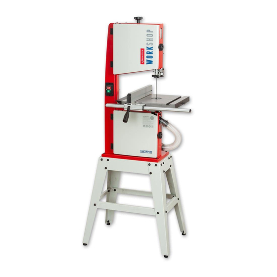
- Page 1 AW1950B Code 107711 Original Instructions Bandsaws 10" Inch AT: 23/06/2021 BOOK VERSION: 01...
- Page 2 Wiring Diagram Exploded Diagrams/Lists 34-35-36-37 Cert No: MJ3420, MJ3425, EU Declaration of Conformity MJ343C, MJ343B This machine complies with the following directives: Axminster Tool Centre Ltd Axminster Devon EX13 5PH UK 2006/42/EC axminstertools.com EN 1807-1:2013 declares that the machinery described:- EN 60204-1:2006+A1+AC 06/42/EC - Annex I/05.2006...
- Page 3 Fence Rail Scale Strips (see pages 22-23 for mounting instructions) Floor Stand Comprising Leg Brackets Long Upper Support Struts Short Upper Support Struts Long Lower Support Struts Short Lower Support Struts Threaded Rubber Feet Floor Stand Bag of fixings OPTIONAL ACCESSORIES Axminster Craft Mitre Fence (Code 104928) Continues over...
- Page 4 WHAT’S INCLUDED...
- Page 5 WHAT’S INCLUDED/ OPTIONAL ACCESSORIES Optional Mitre Fence HAVING UNPACKED YOUR SAW (SEE BELOW) AND ITS ACCESSORIES PLEASE DISPOSE OF ANY UNWANTED PACKAGING PROPERLY. THE CARDBOARD PACKAGING IS BIODEGRADABLE. GENERAL INSTRUCTIONS FOR 230V MACHINES The following will enable you to observe good working •...
- Page 6 SPECIFICATION Code 107711 Model AW1950B Rating Workshop Power (Output) 550 W Blade Speed 660 & 840 m/min Blade Length 1,950mm Blade Width Min/Max 6 mm to 13 mm Max Width of Cut 260 mm Max Width of Cut with Fence 185 mm Table Size 350 x 330 mm...
- Page 7 ASSEMBLY Step 3 Step 5 Step 4 Step 6 Mounting the Bandsaw to the Stand WHEN MOUNTING THE UNIT, WE STRONGLY ADVISE YOU GET THE ASSISTANCE OF ANOTHER PERSON AS THE BANDSAW IS HEAVY. Lift the saw on to the stand, secure using four long bolts, nuts and washers (10).
- Page 8 ASSEMBLY Tensioning and tracking the blade Fig 03-04 Make sure both top and bottom blade guides and thrust bearing are well clear of the blade, see fig 01 Fig 01 1) Open the front covers fully, giving good access to the top compartment of the saw and good visibility into the bottom compartment, see page 14.
- Page 9 ASSEMBLY 4) Check that the drive belt is tensioned correctly. Tension the DISCONNECT THE SAW FROM drive belt on model, loosen the motors clamping Hex bolt and press the assembly down. While holding motor in place THE MAINS SUPPLY! retighten the Hex bolt, see fig 08. Fig 7-08 Setting the Blade Guides 1) Loosen the blade guide clamp and lower the upper blade...
- Page 10 ASSEMBLY 5) Remove the lower blade guide guard and place safely Rear thrust bearing aside, see fig 16-17. 6) Set the fore and aft position on the guide assembly, as described in step 2 on page 09. Fig 16-17 3) Loosen the grub screw (B) that clamps the rear thrust bearing, position the bearing so it’s 1mm behind the blade, retighten the grub screw, see fig 12-13.
- Page 11 ASSEMBLY Fig 18-19-20 Fig 21-22-23-24 Guide assembly bolt Wheel brush Continues over...
- Page 12 ASSEMBLY Fig 28-29 Mounting the Table Locate the blade tensioning knob (6) and insert it down over the control shaft ,on top of the bandsaw housing, see fig 25. 1) The saw table can be fitted without removing the blade. However, if you would feel more comfortable not having to manoeuvre the table around the blade, remove the blade by opening the top and bottom covers, release the tension on...
- Page 13 ASSEMBLY Fig 32-33 Fence Assembly lower onto the mounting plate, see fig 34. Line up the holes in the tilt quadrant with the ones in the mounting plate, replace 1) Locate the guide fence rail (3) and guide fence assembly (4). the bolts/washers and tighten.
- Page 14 ASSEMBLY 2) Locate the guide fence assembly (4), lowering the fence Fig 46-47 down over the fence rail (3) and press down the locking lever to secure the fence in position, see fig 41-42. Fig 41-42 Retaining clip 2) Place a retaining clip over the end of the hose (7), slide the hose over the port (5) and tighten the clip.
- Page 15 ILLUSTRATION AND PARTS DESCRIPTION Micro switch Upper wheel tracking and tensioning assembly Upper saw wheel Micro switch Wheel brush Bandsaw blade Lower saw wheel Drive belt Drive pulley Continues over...
- Page 16 ILLUSTRATION AND PARTS DESCRIPTION Blade tensioning knob Blade observation window Upper door locking knob Upper door wheel Upper blade guide & guard ‘T’ slot for mitre fence NVR On/Off switch Cast iron table Stabilising bolt Fence locking lever Fence guide rail Saw frame Flexible extraction hose Lower door wheel...
- Page 17 ILLUSTRATION AND PARTS DESCRIPTION Upper wheel Lower wheel...
- Page 18 ILLUSTRATION AND PARTS DESCRIPTION AW1950B Bandsaw Blade tensioning scale Push stick Table levelling stop bolt Motor assembly Dust extraction outlet Blade guide adjusting knob (E) Tilt quadrant (G), Tilt scale (H) Blade guide clamp F) Tilt scale pointer and adjusting screw (I), Lift and shift handle (J)
- Page 19 ILLUSTRATION AND PARTS DESCRIPTION Blade tensioning scale Tracking control knob (A) Tracking butterfly lock (B)
- Page 20 ILLUSTRATION AND PARTS DESCRIPTION Upper blade guide assembly for AW1950B Bandsaw Rear thrust bearing and clamping grub screw (A) Fore and aft clamping grub screw (B) Drive assembly for AW1950B Bandsaw Two speed drive pulley (C)
- Page 21 SETTING UP THE SAW Fig 53 DISCONNECT THE SAW FROM THE MAINS SUPPLY! Checking the Table is Square 1) Loosen the clamping handle beneath the table, lower the table until it rests against its stop. This is a bolt with a lock nut screwed into the underside of the table, see fig 50.
- Page 22 SETTING UP THE SAW Fig 57 Fig 60 Mounting plate Hex screw Grub screws 5) Lower the table down and check that the pointer of the tilt scale reads zero, if not, loosen the Phillips screw and reposition the pointer, see fig 58. 1) Line up the fence (4) with the edge of the tables ‘T’...
- Page 23 SETTING UP THE SAW Fig 67 Pointer Vernier Caliper Pencil line 6) Position the fence to the opposite side of the blade and lock 3) Remove the fence assembly and mark the position of the in place, mark the position with a pencil as before, see fig 67. magnifying glass pointer on the fence rail see fig 64.
- Page 24 OPERATING INSTRUCTIONS 1) Make sure you have read and fully understood the general thrust bearing, the saw would cut and clear the saw line at the instructions and safety precautions that are printed in the rate the work piece was fed into it. If you notice that you require preceding pages of this manual.
- Page 25 CHANGING THE SAW BLADE DISCONNECT THE SAW FROM THE MAINS SUPPLY! 1) Put the table back to the level position if it has been tilted. Open up all blade guides so that they are clear of the blade and open the wheel doors. Set the upper blade guide assembly approximately midway in the throat so the top of the blade guide is level with the centre of the top drive wheel, see fig 71.
- Page 26 CHANGING THE SAW BLADE Drive belt tensioner & tracking control assembly 5) If you are fitting a new blade, it will have been supplied to you “folded” , bound together in this configuration with tape or tie wrap. WARNING! BE VERY CAUTIOUS WHEN YOU “UNFOLD”...
- Page 27 CHANGING THE SAW BLADE Fig 85 DISCONNECT THE SAW FROM THE MAINS SUPPLY! Bandsaw Speed Table Pulley grooves Model Min (Small Pulley) Max (Large Pulley) AW1950B 660m/min 840m/min 1) The bandsaw drive pulley has two speed positions. To change the speed, follow the instructions below. Open the bandsaw wheel doors and release the belt tension on the WARNING! BE VERY CAREFUL WHEN AW1950B bandsaw, loosen the motor Hex bolt, see fig 83 and...
- Page 28 MAINTENANCE DISCONNECT THE SAW FROM THE MAINS SUPPLY! Daily • Keep the machine clean. • Check the saw blade for missing teeth and cracks, see fig 86. • Spray Axcaliber Dry Lubricant on the bare metal surfaces. Fig 86 Check for missing teeth and cracks in the blade Weekly...
- Page 29 50mm. When cutting metals reduce About Axcaliber Bandsaw Blades the speed as much as possible especially when cutting ferrous Axcaliber bandsaw blades are manufactured at Axminster using metals or cast iron. advanced CNC machining, high precision digital measuring equipment and specialised heat treatment facilities.
- Page 30 BANDSAW BLADE INFORMATION Premium Bandsaw Blades •Premium blades made from M42 with 8% cobalt. • Long life with high resistance to heat, abrasion and vibration. • Variable pitch teeth for wider ranging applications. • Also used for cutting metal on horizontal bandsaws. Blades are available in three variable pitch forms 4-6tpi, 6-10tpi and 10-14tpi.
- Page 31 (preventative maintenance) is up-sell items for the bandsaw. Please visit our website at axminstertools.com essential to get the best from your saw. Axminster • This is the most common question that you will get from bandsaw users. Usually the answer lies within Machine the blade;...
- Page 32 INTRODUCTION KEY FEATURES • Bandsaw Buddy is a unique bandsaw blade aligning tool. • Designed and made in Axminster Bandsaw Buddy allows you to check the alignment of the • Unique bandsaw blade aligning tool bandsaw blade to the face of the fence. Most other checks only require the use of a combination or engineer’s square.
- Page 33 WIRING DIAGRAM Model AW1950B...
- Page 34 EXPLODED DIAGRAMS/LISTS AW1950B 10inch (Diagram A)
- Page 35 EXPLODED DIAGRAMS/LISTS AW1950B 10inch (Parts List A) Wing nut Motor pulley Description Adjusting rack,upper guide Guide bracket Protection cover,lower guide Motor Saw frame Lower wheel shaft Micro switch box Upper wheel shaft Upper door Upper wheel shaft seat Lower door Sliding axle bracket Hinge Upper wheel sliding axle...
- Page 36 EXPLODED DIAGRAMS/LISTS AW1950B 10inch (Diagram & Parts List B) (3425-B) Description Table pin Guide piece Right cap,front rail Square neck bolt M6 x 25 Left cap,fence carrier Hex.bolt M8 x 45 Right cap,fence carrier Worktable Screw guide Mounting base,worktable Pointer Rotating base,worktable Locking shaft,fence carrier Extension table...
- Page 37 EXPLODED DIAGRAMS/LISTS Stand (Diagram C) (3425-C) AW1950B 10inch Description Upper long bracket Stand leg Upper short bracket Lower short bracket Lower long bracket Hex.socket pan head screw M6 x 16 Washer 8 Washer 6 Hex.nut M8 Hex.nut M6 Hex.bolt M6 x 35 Hex.bolt M8 x 30 Gasket nut Rubber mat...
- Page 38 The packaging is suitable for recycling. Please dispose of it in a responsible manner. EU Countries Only Do not dispose of electric tools together with household waste material. By law they must be collected and recycled separately. Axminster Tools, Axminster Devon EX13 5PH axminstertools.com...
Need help?
Do you have a question about the WorkShop AW1950B and is the answer not in the manual?
Questions and answers