Table of Contents
Advertisement
Sliding Table Kit
Code: 951539
AW10BSB2 AW12BSB2
Table Extension Set
Setup 1
Setup 2
Code: 951538 AW10BSB2
Code: 951541 AW12BSB2
Saw Bench Package
Code: 718652 AW10BSB2
Code: 718653 AW12BSB2
AW10BSB2,AW12BSB 2
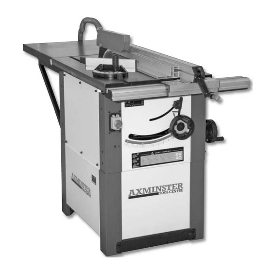
Saw Bench
The Axminster AW10BSB2 and AW12BSB2 Saw Benches are robust machines, constructed largely from
cast iron and heavy gauge steel. The 254mm or 315mm blades give a choice of cutting depth of 75mm
or 100mm, and are amply powered by a 2.2kW or 3kW 1ph induction motors. The cast iron table gives
great strength and rigidity as well as providing a smooth working surface. A full length rip fence, locks
onto rails at the front and back of the table, and is also equiped with a micro positioning adjustment
ensuring straight rip cuts. A mitre fence slides in a T slot groove in the table either side of the blade. Both
the blade height and tilt controls are conveniently located and lock in position. A pressed steel rear feed-
off table is also supplied. Dust extraction is provided on both the crown guard and under the blade for
efficient dust control, a 1,000 m3/hr extractor is recommended. As supplied, these machines are compact
in size but ready for work in the home or light trade workshop. Further options are available. 1, a kit of
two cast iron extension tables that can be fitted either one each side or both to the right of the blade,
complete with longer fence rails, and 2, a fully functioning sliding table kit to allow large board materials
to be cut. When both options are fitted this
saw bench becomes a very useful
machine for most jobs in the
workshop.
Axminster Tool Centre,
Unit 10 Weycroft Avenue, Axminster, Devon EX13 5PH
www.axminster.co.uk
Code: 951537 AW10BSB2
Code: 951540 AW12BSB2
Advertisement
Table of Contents


Need help?
Do you have a question about the AW10BSB2 and is the answer not in the manual?
Questions and answers