
Related Manuals for Axminster AWESBS


Summary of Contents for Axminster AWESBS
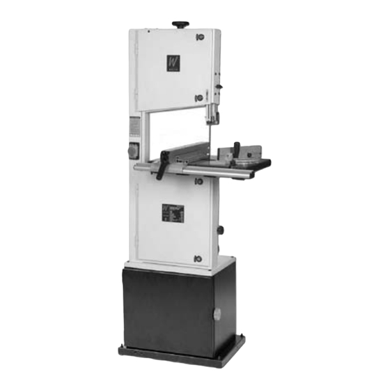
- Page 1 Axminster White Floor Standing Bandsaw A X M I N S T E R Axminster Reference No: AWESBS W H I T E 2003 w w w. a x m i n s t e r. c o . u k...
-
Page 2: Table Of Contents
Index of Contents... Page No. Index of Contents........................02 Declaration of Conformity………….………..……..………….........03 What’s in the Box………….………..……..…………............04 General Instructions for 240v Machines............05-06 Unpacking.........................06 Cabinet Assembly...................07-08-09 Assembling the Bandsaw to the Cabinet..............10 Initial Assembly..................11-12-13-14 Machine Specifications….………..................14 Identification and Description............... 15-17-25 Illustration and Parts Description ............ -
Page 3: Declaration Of Conformity
Declaration of Conformity... A X M I N S T E R W H I T E Copied from CE Certificate The undersigned, F. Mocking authorised by Laizhou City Fulin Electric Co., Ltd. No. 275 Wenquan East Road Laizhou, Shandong 261400 P.R. China declares that this product: Bandsaw MJ343B... -
Page 4: What's In The Box
Keep this Instruction Manual readily accessible for any others who may also be required to use the machine. www.axminster.co.uk... -
Page 5: General Instructions For 240V Machines
General Instructions for 240 v Machines... A X M I N S T E R W H I T E Good Working Practices/Safety The following suggestions will enable you to observe good working practices, keep yourself and fellow workers safe and maintain your tools and equipment in good working order. -
Page 6: Unpacking
“wriggle” the saw off the cardboard. (The best method of moving the saw is with a ‘hug’ lift through the neck of the saw, holding the saw back against your body and lifting by straightening your legs). www.axminster.co.uk... -
Page 7: Cabinet Assembly
Cabinet Assembly ... A X M I N S T E R 13mm Spanner W H I T E Base support plate Step 1 Locate the four rubber foot bolts, remove the first M8 nut and washer (A) and Introduce the rubber foot bolt through the underside of the base support plate and secure in place using the M8 nut and washer you remove earlier Rubber foot bolt... - Page 8 M8 bolt, nut & washer Step 4 Back panel 13mm spanner Slide the back panel in place then secure to the side support panels using six M8x16 bolts, nuts & washers. Then tighten all bolt but DON’T OVER TIGHTEN. www.axminster.co.uk...
- Page 9 Cabinet Assembly ... A X M I N S T E R W H I T E Step 5 Door fastener Hinge pin Line up the door with the two hinge pins and lower in place . Bandsaw cabinet fully assembled...
-
Page 10: Assembling The Bandsaw To The Cabinet
Assembling the Bandsaw to the Cabinet..A X M I N S T E R W H I T E Lift the saw on to the cabinet, and secure using the 4 M8x55 bolts nuts and washers. ( Insert the bolts through the base of the saw, through the floor cabinet and fit the washers and nuts on the underside). -
Page 11: Initial Assembly
Initial Assembly... A X M I N S T E R W H I T E Preparing the saw table for fitting: 1.The saw table can be fitted without removing the blade, however, if you would feel more comfortable not having to manoeuvre the table around the blade (the table is quite heavy), remove the blade by opening the top and bottom covers, release the tension on the blade by backing off the tensioning wheel (See fig 06), and remove the blade, taking care as it is manoeuvred clear of the guides and the safety guards. - Page 12 Initial Assembly... A X M I N S T E R W H I T E Fitting the guide fence assembly Assemble the back rail to the rear of the table by inserting the three Phillips screws through the predrilled holes in the extrusion. Because of the off-centre hole the back rail cannot be fitted the ‘wrong’...
- Page 13 Initial Assembly... A X M I N S T E R W H I T E Fitting the guide fence Fit the guide fence by clipping the rear clamp over the back rail first and dropping the front clamp over the fence rail. (See fig 4) Push down on the lock lever, and ensure the fence clamps up correctly. (See fig 4a) If not, adjust the clamping system by tightening or loosening the nut on the end of the torsion rod at the rear end of the guide fence blade.
-
Page 14: Machine Specifications
‘T’ slot Fence extension Fig 5 Fig 5a M6 Coach bolt M6 Knob and washer Machine Specification... Axminster No. 200434 (AWESBS) Motor 240V a.c, 50Hz, 1400rpm, 1.5hp Wheel Diameter 350mm Blade Speeds (Off Load) 12-10m/s Max Cutting Depth.(Throat) (Upright) 200mm... -
Page 15: Identification And Description
Identification and Description... A X M I N S T E R W H I T E Main saw frame The main body of the machine that all the other parts are mounted upon. (See fig 6) Upper and lower The two doors that cover the upper and lower saw wheel compartments. cover doors There are interlocks fitted to both doors so that the machine cannot (See fig 6) -
Page 16: Illustration And Parts Description
Illustration and Parts Description... A X M I N S T E R W H I T E Fig 6 Blade tensioning wheel Upper saw wheel (inside cover door see fig 8) Upper cover door latches Upper cover door Upper blade guide height clamp Guide fence Upper blade... - Page 17 Identification and Description... A X M I N S T E R W H I T E Saw table insert The saw table insert fits into the round recessed groove in the centre of (See figs 6 &11) the table. It not only fills the round void, it also supports the workpiece below the saw in order to minimise ‘breakout’...
-
Page 18: Illustrated Parts Breakdown
Illustrated Parts Breakdown... A X M I N S T E R W H I T E... - Page 19 Illustrated Parts Breakdown... A X M I N S T E R W H I T E...
-
Page 20: Illustrated Parts List
Illustrated Parts List... A X M I N S T E R W H I T E... - Page 21 Illustrated Parts List... A X M I N S T E R W H I T E...
-
Page 22: Illustrated Parts Breakdown & List
Illustrated Parts Breakdown & List... A X M I N S T E R W H I T E... - Page 23 Illustrated Parts Breakdown & List... A X M I N S T E R W H I T E Cabinet...
- Page 24 Illustration and Parts Description... A X M I N S T E R W H I T E Blade tension indicator Blade tensioning wheel Upper blade guide height adjusting knob Tracking control knob Mitre fence Guide fence Saw table Tilt quadrant Tilt mechanism clamp Quadrant...
- Page 25 Identification and Description... A X M I N S T E R W H I T E Back rail An aluminium extrusion bolted to the rear of the saw table, that is used (See fig 1) as the rear clamp bracket for the guide fence. Tracking control The tracking control knob, at the rear of the top compartment, is knob connected to a threaded rod that is engaged in a threaded hole in the...
- Page 26 W H I T E Blade tensioning wheel Upper wheel mounting assembly Upper saw wheel Upper blade guide height mechanism Upper blade guide height clamp Micro switch Idler wheel adjusting knob Lower saw wheel Fig 8 Drive belt tensioning idler wheel www.axminster.co.uk...
- Page 27 Illustration and Parts Description... A X M I N S T E R W H I T E Tilt quadrant Saw table Fig 9 Table preset Scale level stop Tilt scale pointer Tilt mechanism clamp Quadrant housing Typ. 4 Butterfly bolts Fig 10 Unlock Lock...
- Page 28 Illustration and Parts Description... A X M I N S T E R W H I T E Mitre scale Saw table insert Mitre fence Fig 11 Pointer Typ. 2‘T’ Slot Fig 12 Upper blade guide height clamp Upper door latch www.axminster.co.uk...
- Page 29 Illustration and Parts Description... A X M I N S T E R W H I T E Upper thrust bearing Guide assembly cap head bolt Fig 14 Fig 13 Cap head bolts Cap head bolt for Typ. 2 Upper blade guides thrust bearing Lower blade guard Lower blade guide...
-
Page 30: Setting Up The Saw
Setting Up the Saw... A X M I N S T E R W H I T E DISCONNECT THE SAW FROM THE MAINS SUPPLY Tensioning and tracking the blade Make sure both top and bottom blade guides are well clear of the blade. Open the front covers fully, giving good access to the top compartment of the saw and good visibility into the bottom compartment (see fig 8). -
Page 31: Setting The Fence
Setting the Fence... A X M I N S T E R W H I T E To make sure the guide fence is at 90˚line up the guide fence with the edge of the tables ‘T’ slot. If you find that the fence is out of alignment follow the steps below: Note: It is recommended that you remove the extension fence to make it easier to line the fence up. -
Page 32: Operating Instructions
If the workpiece is exceptionally small, find something to use as a sacrificial carrier and mount the workpiece on it with double sided tape, or similar. 12. Remember to check the blade tension after a new blade has been ‘working’ for 30-60 mins. The blade will ‘stretch’ slightly when new. www.axminster.co.uk... -
Page 33: Changing The Saw Blade
Operating Instructions... A X M I N S T E R W H I T E 13. Do not release the tension on the saw blade when work is complete. The blades and the main saw frame do not respond kindly to constant changes in stress and tension. Only release the tension to change the blade or if the blade is to be removed because the machine is to be ‘mothballed’... -
Page 34: Notes
Notes... A X M I N S T E R W H I T E www.axminster.co.uk... - Page 35 Notes ... A X M I N S T E R W H I T E 0800 371822 FREEPHONE...
- Page 36 Axminster Reference No: AWESBS A X M I N S T E R W H I T E Axminster Devon EX13 5PH UK FREEPHONE 0800 371822 www.axminster.co.uk 2003...
Need help?
Do you have a question about the AWESBS and is the answer not in the manual?
Questions and answers
Hvordan skifter jeg drivremmen