Table of Contents
Advertisement
Quick Links
® ® ® ® ®
Intel
Intel
Intel
Pentium
Pentium
Pentium
Intel
Intel
Pentium
Pentium
Pedestal
Pedestal
Server
Server
Pedestal
Pedestal
Pedestal Server
Server
Server
1066/800 MHz Front Side Bus
TS100-E3
® ® ® ® ®
4/Pentium
4/Pentium
4/Pentium
4/Pentium
4/Pentium
® ® ® ® ®
D LGA775
D LGA775
D LGA775
D LGA775
D LGA775
Advertisement
Table of Contents

Related Manuals for Asus TS100-E3


Summary of Contents for Asus TS100-E3
- Page 1 TS100-E3 ® ® ® ® ® ® ® ® ® ® ® ® ® ® ® Intel Intel Intel Pentium Pentium Pentium 4/Pentium 4/Pentium 4/Pentium D LGA775 D LGA775 D LGA775 Intel Intel Pentium Pentium 4/Pentium 4/Pentium D LGA775 D LGA775...
- Page 2 (including damages for loss of profits, loss of business, loss of use or data, interruption of business and the like), even if ASUS has been advised of the possibility of such damages arising from any defect or error in this manual or product.
-
Page 3: Table Of Contents
Contents Notices ....................vii Safety information ................viii About this guide ................. ix Chapter 1: Product introduction Chapter 1: Product introduction Chapter 1: Product introduction Chapter 1: Product introduction Chapter 1: Product introduction System package contents ............ 1-2 System specifications ............1-3 Front panel features ............. - Page 4 Managing and updating your BIOS ........4-2 4.1.1 Creating a bootable floppy disk ......4-2 4.1.2 AFUDOS utility ............4-3 4.1.3 ASUS CrashFree BIOS 2 utility ........ 4-5 4.1.4 ASUS Update utility ..........4-7 BIOS setup program ............4-10 4.2.1 BIOS menu screen ..........4-11 4.2.2...
- Page 5 Contents Main menu ................4-13 4.3.1 System Time ............4-13 4.3.2 System Date ............4-13 4.3.3 Legacy Diskette A ..........4-13 4.3.4 Primary/Secondary/Third IDE Master/Slave ..4-14 4.3.5 IDE Configuration ..........4-15 4.3.6 System Information ..........4-17 Advanced menu ..............4-18 4.4.1 USB Configuration ..........
- Page 6 Contents 5.2.6 Deleting a RAID configuration ....... 5-23 6.2.7 Selecting the boot drive from a RAID set ..... 5-24 6.2.8 Enabling the WriteCache ........5-25 Global Array Manager ............5-25 Chapter 6: Chapter 6: Driver installation Driver installation Chapter 6: Chapter 6: Chapter 6: Driver installation...
-
Page 7: Notices
Notices Federal Communications Commission Statement Federal Communications Commission Statement Federal Communications Commission Statement Federal Communications Commission Statement Federal Communications Commission Statement This device complies with Part 15 of the FCC Rules. Operation is subject to the following two conditions: • This device may not cause harmful interference, and •... -
Page 8: Safety Information
Safety information Electrical Safety Electrical Safety Electrical Safety Electrical Safety Electrical Safety • Before installing or removing signal cables, ensure that the power cables for the system unit and all attached devices are unplugged. • To prevent electrical shock hazard, disconnect the power cable from the electrical outlet before relocating the system. -
Page 9: About This Guide
About this guide Audience Audience Audience Audience Audience This user guide is intended for system integrators and experienced users with at least basic knowledge of configuring a server. Contents Contents Contents Contents Contents This guide contains the following parts: 1 . 1 . C h a p t e r 1 : P r o d u c t I n t r o d u c t i o n C h a p t e r 1 : P r o d u c t I n t r o d u c t i o n C h a p t e r 1 : P r o d u c t I n t r o d u c t i o n... - Page 10 N O T E : Tips and information to aid in completing a task. Reference Reference Reference Reference Reference Visit the ASUS websites worldwide that provide updated information for all ASUS hardware and software products. Refer to the ASUS contact information for details. x x x x x...
- Page 11 Chapter 1 This chapter describes the general features of the barebone server, including sections on the front panel and rear panel specifications. A S U S T S 1 0 0 - E 3 A S U S T S 1 0 0 - E 3 A S U S T S 1 0 0 - E 3 A S U S T S 1 0 0 - E 3 A S U S T S 1 0 0 - E 3...
-
Page 12: System Package Contents
System package contents Check your ASUS TS100-E3 package with the items on the following table. The package contents vary for the following configurations: I t e m D e s c r i p t i o n I t e m D e s c r i p t i o n... -
Page 13: System Specifications
System specifications The ASUS TS100-E3 is a barebone server system featuring the ASUS P5MT Series motherboard. The server supports an Intel ® Pentium ® 4/Pentium ® processor in the 775-land package, and includes the latest technologies through the chipsets embedded on the motherboard. - Page 14 M a n a g e m e n t M a n a g e m e n t ASUS Server Web-based Management (ASWM) 2.0 M a n a g e m e n t M a n a g e m e n t...
-
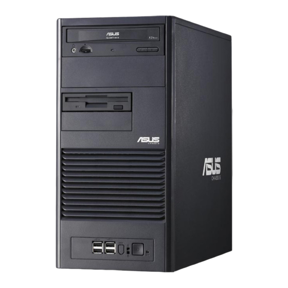
Page 15: Front Panel Features
Front panel features The TS100-E3 chassis displays a stylish front bezel with lock. The bezel covers the system components on the front panel and serves as security. Open the bezel to access the front panel components. The drive bays, power and reset buttons, LED indicators, CD-ROM drive, floppy drive, and USB 2.0 ports are... -
Page 16: Rear Panel Features
Rear panel features The rear panel includes a slot for the motherboard rear I/O ports, expansion slots, a chassis lock and intrusion switch, a vent for the system fan, and power supply module. P o w e r P o w e r c o n n e c t o r c o n n e c t o r P o w e r... -
Page 17: Internal Features
8 8 8 8 8 3 3 3 3 3 4 4 4 4 4 Power supply module Chassis fan ASUS P5MT motherboard Expansion card slots Optical drive 1 x 5.25-inch drive bay Floppy drive 2 x internal 3.5-inch drive bays... -
Page 18: Led Information
LED information The barebone system comes with five LED indicators. Refer to the following table for the LED status description. System and HDD LED System and HDD LED System and HDD LED System and HDD LED System and HDD LED P o w e r L E D ( b l u e ) P o w e r L E D ( b l u e ) P o w e r L E D ( b l u e ) - Page 19 Chapter 2 This chapter lists the hardware setup procedures that you have to perform when installing or removing system components. A S U S T S 1 0 0 - E 3 A S U S T S 1 0 0 - E 3 A S U S T S 1 0 0 - E 3 A S U S T S 1 0 0 - E 3 A S U S T S 1 0 0 - E 3...
-
Page 20: Chapter 2: Hardware Setup
Chassis cover The chassis features a “screwless design” that allows convenient assembly and disassembly. You can simply push or slide mechanical bolts and locks to remove the cover. 2.1.1 2.1.1 2.1.1 Removing the side cover Removing the side cover Removing the side cover 2.1.1 2.1.1 Removing the side cover... -
Page 21: Reinstalling The Side Cover
You may need to remove some of the installed components to access the DIMM sockets and internal connectors. Refer to section “2.10 Removable components” for instructions. 2.1.2 2.1.2 2.1.2 Reinstalling the side cover Reinstalling the side cover Reinstalling the side cover 2.1.2 2.1.2 Reinstalling the side cover... -
Page 22: Motherboard Overview
Motherboard overview The barebone server comes with the P5MT-MX/C motherboard installed. The motherboard is secured to the chassis by eight (8) screws as indicated by the circles in the illustration below. Refer to “Chapter 4 Motherboard information” for detailed information on the motherboard. -
Page 23: Central Processing Unit (Cpu)
Central Processing Unit (CPU) The motherboard comes with a surface mount LGA775 socket designed for the Intel ® Pentium ® 4 processor in the 775-land package 2.3.1 2.3.1 2.3.1 Installing the CPU Installing the CPU Installing the CPU 2.3.1 2.3.1 Installing the CPU Installing the CPU To install a CPU:... - Page 24 Lift the load lever in the direction of the arrow to a 135º angle. Lift the load plate with your thumb and forefinger to a 100º angle (A), then push the PnP cap from the load plate window to remove (B). L o a d p l a t e L o a d p l a t e L o a d p l a t e...
- Page 25 The CPU fits in only one correct orientation. DO NOT force the CPU into the socket. It may bend the connectors on the socket and damage the CPU! Close the load plate (A), then push the load lever (B) until it snaps into the retention tab.
-
Page 26: Installing The Cpu Heatsink And Airduct Assembly
The TS100-E3 comes with a proprietary CPU heatsink. You have to assemble the CPU heatsink before installing to the motherboard. To install the CPU heatsink and airduct assembly: Locate the four screw holes on the motherboard. - Page 27 CPU_FAN2 FANOUT7 FANPWR3 ® CPU_FAN1 FANOUT4 FANPWR2 P5MT-MX/C CPU Fan Connectors Do not forget to connect the CPU fan connector! Hardware monitoring errors may occur if you fail to plug the connector. A S U S T S 1 0 0 - E 3 A S U S T S 1 0 0 - E 3 A S U S T S 1 0 0 - E 3 2 - 9...
-
Page 28: System Memory
Always install DIMMs with the same CAS latency. For optimum compatibility, it is recommended that you obtain memory modules from the same vendor. Refer to the DDR2 Qualified Vendors List at the ASUS web site. • When installing one or two DIMMs, install the DIMM(s) to the blue slots (DIMM_A2/DIMM_B2). -
Page 29: Installing A Dimm
2.4.3 2.4.3 2.4.3 Installing a DIMM Installing a DIMM Installing a DIMM 2.4.3 2.4.3 Installing a DIMM Installing a DIMM Unplug the power supply before adding or removing DIMMs or other system components. Failure to do so may cause severe damage to both the motherboard and the components. -
Page 30: Expansion Slots
Expansion slots In the future, you may need to install expansion cards. The following sub- sections describe the slots and the expansion cards that they support. Make sure to unplug the power cord before installing or removing expansion cards. Failure to do so may cause physical injury, and damage to the cards and motheboard components! 2.5.1 2.5.1... -
Page 31: Interrupt Assignments
2.5.3 2.5.3 2.5.3 2.5.3 2.5.3 Interrupt assignments Interrupt assignments Interrupt assignments Interrupt assignments Interrupt assignments S t a n d a r d i n t e r r u p t a s s i g n m e n t s S t a n d a r d i n t e r r u p t a s s i g n m e n t s S t a n d a r d i n t e r r u p t a s s i g n m e n t s S t a n d a r d i n t e r r u p t a s s i g n m e n t s... -
Page 32: Pci Express Slot
2.5.4 2.5.4 2.5.4 PCI Express slot PCI Express slot PCI Express slot 2.5.4 2.5.4 PCI Express slot PCI Express slot This motherboard supports PCI Express network cards, SCSI cards, and other cards that comply with PCI Express 1.0a specifications. Due to the limits of chipset, if users install a PCI Express X16 graphic card, the link speed will downgrade to x1. -
Page 33: Front Panel Assembly
Front panel assembly 2.6.1 2.6.1 2.6.1 Removing the front panel assembly Removing the front panel assembly Removing the front panel assembly 2.6.1 2.6.1 Removing the front panel assembly Removing the front panel assembly Before installing a 5.25-inch drive, you should first remove the front panel assembly (front bezel and front panel cover). - Page 34 Unhook the hinge-like tabs from the holes on the right side of the front panel to completely detach the front panel assembly from the chassis. Do not use too much force when removing the front panel assembly. H i n g e - l i k e t a b H i n g e - l i k e t a b H i n g e - l i k e t a b H i n g e - l i k e t a b...
-
Page 35: Reinstalling The Front Panel Assembly
2.6.2 2.6.2 Reinstalling the front panel assembly Reinstalling the front panel assembly 2.6.2 2.6.2 2.6.2 Reinstalling the front panel assembly Reinstalling the front panel assembly Reinstalling the front panel assembly To reinstall the front panel assembly (front bezel and front panel cover): Insert the three hinge-like tabs to the holes on the right edge of the chassis. -
Page 36: Inch Drives
5.25-inch drives If you have powered up the system, make sure to unplug the AC power cable before installing or removing any system components. Failure to do so may cause damage to the motherboard and other system components! Two 5.25-inch drive bays are located on the upper front part of the chassis. - Page 37 Make sure that the drive and bay hole align as shown. When in place, the drive protrudes about an inch from the front panel. Secure the drive with a screw. Connect the IDE cable to the IDE connector on the back of the drive.
- Page 38 On the front panel assembly, detach the plastic bay cover opposite the 5.25-inch drive that you installed by pressing the two hooked tabs on each side of the bay cover. Reinstall the front panel assembly when done. Refer to section “2.5.2 Reinstalling the front panel assembly”...
-
Page 39: Hard Disk Drives
Hard disk drives 2.8.1 2.8.1 2.8.1 Removing a SATA HDD Removing a SATA HDD Removing a SATA HDD 2.8.1 2.8.1 Removing a SATA HDD Removing a SATA HDD Follow the instructions in this section to remove a SATA hard disk drive (HDD). First remove both side covers. -
Page 40: Installing A Sata Hdd
2.8.2 2.8.2 2.8.2 Installing a SATA HDD Installing a SATA HDD Installing a SATA HDD 2.8.2 2.8.2 Installing a SATA HDD Installing a SATA HDD Follow the instructions in this section to install a SATA hard disk drive (HDD). First remove both side covers. Then, install the SATA HDD. -
Page 41: Expansion Cards
Expansion cards Refer to this section when installing expansion cards. Make sure to unplug the power cord before installing or removing expansion cards. Failure to do so may cause physical injury, and damage to the cards and motheboard components! 2.9.1 2.9.1 Installing an expansion card Installing an expansion card... - Page 42 After installing the expansion card, put the metal bracket back. Adjust the metal bracket to the locking pawl and screw it tightly. 2 - 2 4 2 - 2 4 2 - 2 4 C h a p t e r 2 : H a r d w a r e s e t u p C h a p t e r 2 : H a r d w a r e s e t u p C h a p t e r 2 : H a r d w a r e s e t u p 2 - 2 4...
-
Page 43: Removing An Expansion Card
2.9.2 2.9.2 Removing an expansion card Removing an expansion card 2.9.2 2.9.2 2.9.2 Removing an expansion card Removing an expansion card Removing an expansion card To remove an expansion card: Remove the side cover. Lay the chassis on its side. For removing an expansion card, unscrew the metal bracket and remove it. -
Page 44: 2.10 Cable Connections
2.10 Cable connections • The bundled system cables are pre-connected before shipped. You do not need to disconnect these cables unless you need to remove pre-installed components for additional device installation. • Refer to Chapter 4 for detailed information on the connectors. 2.10.1 2.10.1 Motherboard connections... -
Page 45: Front I/O Board
2.11 Removable components You may need to remove previously installed system components when installing, removing system devices, or when replacing defective components. This section tells how to remove the following components: Chassis fan Floppy disk drive module Front I/O board Power supply unit 2.11.1 2.11.1... - Page 46 To reinstall the chassis fan: Align the chassis fan holes to the screw holes on the chassis. Drive in the four screws you removed earlier to secure the fan to the chassis. Plug the chassis fan cable to the connector on the motherboard. 2 - 2 8 2 - 2 8 2 - 2 8...
- Page 47 2.11.2 2.11.2 Floppy disk drive Floppy disk drive 2.11.2 2.11.2 2.11.2 Floppy disk drive Floppy disk drive Floppy disk drive You need to remove the front panel assembly before you can remove the floppy disk drive. Refer to section “2.5.1 Removing the front panel assembly” for instructions.
- Page 48 To install a floppy disk drive: Position the floppy drive into the chassis until the drive fits the front edge of the bay. Screw the floppy disk drive tightly. Connect the drive signal cable and power cable. F l o p p y d r i v e p o w e r c a b l e F l o p p y d r i v e p o w e r c a b l e F l o p p y d r i v e p o w e r c a b l e F l o p p y d r i v e p o w e r c a b l e...
- Page 49 2.11.3 2.11.3 Front I/O board Front I/O board 2.11.3 2.11.3 Front I/O board 2.11.3 Front I/O board Front I/O board You need to remove the front panel assembly before you can remove the front I/O board. Refer to section “2.5.1 Removing the front panel assembly” for instructions.
- Page 50 To install the front I/O board: First, put the front I/O board into the chassis with caution. Then, fasten the he front I/O board with screws. Last, connect all the cables to the board respectively. 2 - 3 2 2 - 3 2 2 - 3 2 C h a p t e r 2 : H a r d w a r e s e t u p C h a p t e r 2 : H a r d w a r e s e t u p...
- Page 51 2.11.4 2.11.4 Power supply unit Power supply unit 2.11.4 2.11.4 2.11.4 Power supply unit Power supply unit Power supply unit Refer to this section when removing or installing a power supply unit to the barebone system. You MUST disconnect all power cable plugs from the motherboard along with installed devices before removing the power supply unit.
- Page 52 To remove the power supply unit (PSU): Remove the chassis cover. Refer to section “2.1.1 Removing the side cover.” Remove the front panel assembly. Refer to section “2.5.1 Removing the front panel assembly. Lay the chassis on a flat, stable surface.
- Page 53 To reinstall the power supply unit: Remove the chassis cover. Refer to section “2.1.1 Removing the side cover.” Remove the front panel assembly. Refer to section “2.5.1 Removing the front panel assembly. Lay the chassis on a flat, stable surface. Carefully slide the PSU in the direction of the arrow.
- Page 54 2 - 3 6 2 - 3 6 2 - 3 6 C h a p t e r 2 : H a r d w a r e s e t u p C h a p t e r 2 : H a r d w a r e s e t u p C h a p t e r 2 : H a r d w a r e s e t u p 2 - 3 6 2 - 3 6...
- Page 55 Chapter 3 This chapter gives information about the motherboard that comes with the server. This chapter includes the motherboard layout, jumper settings, and connector locations. A S U S T S 1 0 0 - E 3 A S U S T S 1 0 0 - E 3 A S U S T S 1 0 0 - E 3 A S U S T S 1 0 0 - E 3 A S U S T S 1 0 0 - E 3...
-
Page 56: Motherboard Layouts
Motherboard layouts P5MT-MX/C model P5MT-MX/C model P5MT-MX/C model P5MT-MX/C model P5MT-MX/C model 24.5cm (9.6in) FM_CPU2 PS/2KBMS CPU_FAN2 KBPWR T: Mouse B: Keyboard SUPER I/O ATX12V1 USB12 CPU_FAN1 LGA775 USBPW12 FM_CPU1 COM1 ® VGA1 LAN_EN1 Broadcd LAN1 BCM5753 Intel E7230 VGA_EN1 PCIE1 RAID_SEL1 CR2032 3... - Page 57 Layout contents Layout contents Layout contents Layout contents Layout contents J u m p e r s J u m p e r s J u m p e r s P a g e P a g e P a g e J u m p e r s J u m p e r s P a g e...
-
Page 58: Jumpers
Jumpers The grayed out components in the illustrations may not be present in certain models. 1 . 1 . C l e a r R T C R A M ( C L R T C ) C l e a r R T C R A M ( C L R T C ) C l e a r R T C R A M ( C L R T C ) C l e a r R T C R A M ( C L R T C ) C l e a r R T C R A M ( C L R T C ) - Page 59 2 . 2 . C P U f a n p i n s e l e c t i o n ( 3 - p i n F M _ C P U 1 , F M _ C P U 2 ) C P U f a n p i n s e l e c t i o n ( 3 - p i n F M _ C P U 1 , F M _ C P U 2 ) C P U f a n p i n s e l e c t i o n ( 3 - p i n F M _ C P U 1 , F M _ C P U 2 ) C P U f a n p i n s e l e c t i o n ( 3 - p i n F M _ C P U 1 , F M _ C P U 2 )
- Page 60 4 . 4 . K e y b o a r d p o w e r ( 3 - p i n K B P W R 1 ) K e y b o a r d p o w e r ( 3 - p i n K B P W R 1 ) K e y b o a r d p o w e r ( 3 - p i n K B P W R 1 ) K e y b o a r d p o w e r ( 3 - p i n K B P W R 1 ) K e y b o a r d p o w e r ( 3 - p i n K B P W R 1 )
- Page 61 6 . 6 . G i g a b i t L A N c o n t r o l l e r s e t t i n g ( 3 - p i n L A N _ E N 1 ) G i g a b i t L A N c o n t r o l l e r s e t t i n g ( 3 - p i n L A N _ E N 1 ) G i g a b i t L A N c o n t r o l l e r s e t t i n g ( 3 - p i n L A N _ E N 1 ) G i g a b i t L A N c o n t r o l l e r s e t t i n g ( 3 - p i n L A N _ E N 1 )
- Page 62 8 . 8 . F o r c e B I O S r e c o v e r y s e t t i n g ( 3 - p i n R E C O V E R Y 1 ) F o r c e B I O S r e c o v e r y s e t t i n g ( 3 - p i n R E C O V E R Y 1 ) F o r c e B I O S r e c o v e r y s e t t i n g ( 3 - p i n R E C O V E R Y 1 ) F o r c e B I O S r e c o v e r y s e t t i n g ( 3 - p i n R E C O V E R Y 1 )
-
Page 63: Connectors
Connectors 3.3.1 3.3.1 3.3.1 Rear panel connectors Rear panel connectors Rear panel connectors 3.3.1 3.3.1 Rear panel connectors Rear panel connectors 1 . 1 . P S / 2 m o u s e p o r t ( g r e e n ) . P S / 2 m o u s e p o r t ( g r e e n ) . -
Page 64: Internal Connectors
3.3.2 3.3.2 Internal connectors Internal connectors 3.3.2 3.3.2 3.3.2 Internal connectors Internal connectors Internal connectors 1 . 1 . F l o p p y d i s k d r i v e c o n n e c t o r ( 3 4 - 1 p i n F L O P P Y ) F l o p p y d i s k d r i v e c o n n e c t o r ( 3 4 - 1 p i n F L O P P Y ) F l o p p y d i s k d r i v e c o n n e c t o r ( 3 4 - 1 p i n F L O P P Y ) F l o p p y d i s k d r i v e c o n n e c t o r ( 3 4 - 1 p i n F L O P P Y ) - Page 65 3 . 3 . 3 . 3 . Serial ATA connectors (7-pin SATA1, SATA2, SATA3, SATA4) Serial ATA connectors (7-pin SATA1, SATA2, SATA3, SATA4) Serial ATA connectors (7-pin SATA1, SATA2, SATA3, SATA4) Serial ATA connectors (7-pin SATA1, SATA2, SATA3, SATA4) Serial ATA connectors (7-pin SATA1, SATA2, SATA3, SATA4) These connectors are for the Serial ATA signal cables to Serial ATA hard disk drives.
- Page 66 4 . 4 . H a r d d i s k a c t i v i t y L E D c o n n e c t o r ( 4 - p i n H D L E D 1 ) H a r d d i s k a c t i v i t y L E D c o n n e c t o r ( 4 - p i n H D L E D 1 ) H a r d d i s k a c t i v i t y L E D c o n n e c t o r ( 4 - p i n H D L E D 1 ) H a r d d i s k a c t i v i t y L E D c o n n e c t o r ( 4 - p i n H D L E D 1 )
- Page 67 6 . 6 . S e r i a l p o r t c o n n e c t o r ( 1 0 - 1 p i n C O M 2 ) S e r i a l p o r t c o n n e c t o r ( 1 0 - 1 p i n C O M 2 ) S e r i a l p o r t c o n n e c t o r ( 1 0 - 1 p i n C O M 2 ) S e r i a l p o r t c o n n e c t o r ( 1 0 - 1 p i n C O M 2 ) S e r i a l p o r t c o n n e c t o r ( 1 0 - 1 p i n C O M 2 )
- Page 68 8 . 8 . C P U , C h a s s i s a n d p o w e r f a n c o n n e c t o r s ( 3 - p i n C P U , C h a s s i s a n d p o w e r f a n c o n n e c t o r s ( 3 - p i n C P U , C h a s s i s a n d p o w e r f a n c o n n e c t o r s ( 3 - p i n C P U , C h a s s i s a n d p o w e r f a n c o n n e c t o r s ( 3 - p i n...
- Page 69 1 0 . 1 0 . S S I p o w e r c o n n e c t o r s ( 2 4 - p i n A T X P W R 1 , 4 - p i n A T X 1 2 V 1 ) S S I p o w e r c o n n e c t o r s ( 2 4 - p i n A T X P W R 1 , 4 - p i n A T X 1 2 V 1 ) 1 0 .
- Page 70 1 2 . 1 2 . 1 2 . 1 2 . 1 2 . S y s t e m p a n e l c o n n e c t o r ( 2 0 - p i n P A N E L 1 ) S y s t e m p a n e l c o n n e c t o r ( 2 0 - p i n P A N E L 1 ) S y s t e m p a n e l c o n n e c t o r ( 2 0 - p i n P A N E L 1 ) S y s t e m p a n e l c o n n e c t o r ( 2 0 - p i n P A N E L 1 )
- Page 71 Chapter 4 This chapter tells how to change system settings through the BIOS Setup menus and describes the BIOS parameters. A S U S T S 1 0 0 - E 3 A S U S T S 1 0 0 - E 3 A S U S T S 1 0 0 - E 3 A S U S T S 1 0 0 - E 3 A S U S T S 1 0 0 - E 3...
-
Page 72: Managing And Updating Your Bios
Refer to the corresponding sections for details on these utilities. Save a copy of the original motherboard BIOS file to a bootable floppy disk in case you need to restore the BIOS in the future. Copy the original motherboard BIOS using the ASUS Update or AFUDOS utilities. 4.1.1 4.1.1 4.1.1... -
Page 73: Afudos Utility
E x t e n s i o n n a m e Press <Enter>. The utility copies the current BIOS file to the floppy disk. A:\>afudos /oOLDBIOS1.rom AMI Firmware Update Utility - Version 1.19(ASUS V2.07(03.11.24BB)) Copyright (C) 2002 American Megatrends, Inc. All rights reserved. Reading flash ..done Write to file.. - Page 74 Updating the BIOS file To update the BIOS file with the AFUDOS utility: Visit the ASUS website (www.asus.com) and download the latest BIOS file for the motherboard. Save the BIOS file to a bootable floppy disk. Write the BIOS filename on a piece of paper. You need to type the exact BIOS filename at the DOS prompt.
-
Page 75: Asus Crashfree Bios 2 Utility
ASUS CrashFree BIOS 2 utility ASUS CrashFree BIOS 2 utility The ASUS CrashFree BIOS 2 is an auto recovery tool that allows you to restore the BIOS file when it fails or gets corrupted during the updating process. You can update a corrupted BIOS file using the motherboard support CD or the floppy disk that contains the updated BIOS file. - Page 76 Restart the system after the utility completes the updating process. The recovered BIOS may not be the latest BIOS version for this motherboard. Visit the ASUS website (www.asus.com) to download the latest BIOS file. 4 - 6 4 - 6...
-
Page 77: Asus Update Utility
ASUS Update utility 4.1.4 4.1.4 ASUS Update utility ASUS Update utility The ASUS Update is a utility that allows you to manage, save, and update the motherboard BIOS in Windows ® environment. The ASUS Update utility allows you to: • Save the current BIOS file •... - Page 78 Updating the BIOS through the Internet Updating the BIOS through the Internet Updating the BIOS through the Internet To update the BIOS through the Internet: Launch the ASUS Update utility from the Windows ® desktop by clicking S t a r t...
- Page 79 Updating the BIOS through a BIOS file Updating the BIOS through a BIOS file Updating the BIOS through a BIOS file To update the BIOS through a BIOS file: Launch the ASUS Update utility from the Windows ® desktop by clicking S t a r t S t a r t S t a r t >...
-
Page 80: Bios Setup Program
The BIOS setup screens shown in this section are for reference purposes only, and may not exactly match what you see on your screen. • Visit the ASUS website (www.asus.com) to download the latest BIOS file for this motherboard. 4 - 1 0... -
Page 81: Bios Menu Screen
[SHIFT-TAB] to Legacy Diskette A [1.44M, 3.5 in] select a field. Primary IDE Master [HDS722516VLSAB0] Primary IDE Slave [ASUS CD-S520/A4] Use [+] or [-] to Third IDE Master [Not Detected] configure system time. Third IDE Slave [Not Detected] Fourth IDE Master... -
Page 82: Menu Items
M a i n Use [+] or [-] to configure system Primary IDE Master : [HDS722516VLSAB0] time. Primary IDE Slave : [ASUS CD-S520/A4] shows the Main menu items. Third IDE Master : [Not Detected] Third IDE Slave : [Not Detected] Select Screen... -
Page 83: Main Menu
Legacy Diskette A [1.44M, 3.5 in] Primary IDE Master [HDS722516VLSAB0] Use [+] or [-] to Primary IDE Slave [ASUS CD-S520/A4] configure system time. Third IDE Master [Not Detected] Third IDE Slave [Not Detected] Fourth IDE Master [Not Detected]... - Page 84 4.3.4 4.3.4 Primary, Third, and Fourth IDE Master/Slave Primary, Third, and Fourth IDE Master/Slave 4.3.4 4.3.4 4.3.4 Primary, Third, and Fourth IDE Master/Slave Primary, Third, and Fourth IDE Master/Slave Primary, Third, and Fourth IDE Master/Slave The items in this menu allow you to set or change the configurations for the IDE devices installed in the system.
-
Page 85: Ide Configuration
Block (Multi-sector Transfer) [Auto] Block (Multi-sector Transfer) [Auto] Block (Multi-sector Transfer) [Auto] Block (Multi-sector Transfer) [Auto] Block (Multi-sector Transfer) [Auto] Enables or disables data multi-sectors transfers. When set to [Auto], the data transfer from and to the device occurs multiple sectors at a time if the device supports multi-sector transfer feature. - Page 86 Onboard IDE Operate Mode [Enhanced Mode] Onboard IDE Operate Mode [Enhanced Mode] Onboard IDE Operate Mode [Enhanced Mode] Onboard IDE Operate Mode [Enhanced Mode] Onboard IDE Operate Mode [Enhanced Mode] Allows selection of the IDE operation mode depending on the installed operating system (OS).
-
Page 87: System Information
This mode allows you to enable or disable Advanced Host Controller Interface (AHCI) Port3 Interlock Switch. Configuration options: [Disabled] [Enabled] ALPE and ASP and the sub-options will show up only when Configure SATA As is set up as [ACHI] IDE Detect Time Out (Sec) [35] IDE Detect Time Out (Sec) [35] IDE Detect Time Out (Sec) [35] IDE Detect Time Out (Sec) [35]... -
Page 88: Advanced Menu
Advanced menu The Advanced menu items allow you to change the settings for the CPU and other system devices. Be cautious when changing the settings of the Advanced menu items. Incorrect field values can cause the system malfunction. BIOS SETUP UTILITY Advanced Configure the USB USB Configuration... -
Page 89: Mps Configuration
USB Function [8 USB Ports] USB Function [8 USB Ports] USB Function [8 USB Ports] USB Function [8 USB Ports] USB Function [8 USB Ports] Allows you to enable a specific number of USB ports, or disable the USB function. Configuration options: [Disabled] [2 USB Ports] [4 USB Ports] [6 USB Ports] [8 USB Ports] Legacy USB Support [Auto] Legacy USB Support [Auto]... -
Page 90: Remote Access Configuration
4.4.3 4.4.3 Remote Access Configuration Remote Access Configuration 4.4.3 4.4.3 4.4.3 Remote Access Configuration Remote Access Configuration Remote Access Configuration BIOS SETUP UTILITY Advanced Configure Remote Access type and parameters Select Remote Access type. Remote Access [Disabled] Remote Access [Disabled] Remote Access [Disabled] Remote Access [Disabled] Remote Access [Disabled]... -
Page 91: Cpu Configuration
4.4.4 4.4.4 4.4.4 CPU Configuration CPU Configuration CPU Configuration 4.4.4 4.4.4 CPU Configuration CPU Configuration The items in this menu show the CPU-related information that the BIOS automatically detects. BIOS SETUP UTILITY Advanced Configure advanced CPU settings Sets the ratio Module Version: 3C.0B between CPU Core Clock and the FSB... - Page 92 Hyper-Threading Technology [Enabled] Hyper-Threading Technology [Enabled] Hyper-Threading Technology [Enabled] Hyper-Threading Technology [Enabled] Hyper-Threading Technology [Enabled] Allows you to enable or disable the Hyper-Threading Technology of CPU. Configuration options: [Disabled] [Enabled] When an Intel Pentium4 processor which supports Hyper-Threading Technology is installed, this functioin will then work. Intel(R) Speedstep Technology [Automatic] Intel(R) Speedstep Technology [Automatic] Intel(R) Speedstep Technology [Automatic]...
-
Page 93: Chipset Configuration
4.4.5 4.4.5 Chipset Configuration Chipset Configuration 4.4.5 4.4.5 4.4.5 Chipset Configuration Chipset Configuration Chipset Configuration The Chipset Configuration menu allows you to change the advanced chipset settings. Select an item then press <Enter> to display the sub-menu. BIOS SETUP UTILITY Advanced Advanced Chipset Settings Manual DRAM Drequency... -
Page 94: Onboard Devices Configuration
Memory Remap Feature [Disabled] Memory Remap Feature [Disabled] Memory Remap Feature [Disabled] Memory Remap Feature [Disabled] Memory Remap Feature [Disabled] Allows you to remap the overlap PCI memory over the total physical memory. Configuration options: [Disabled] [Enabled] 4.4.6 4.4.6 4.4.6 Onboard Devices Configuration Onboard Devices Configuration Onboard Devices Configuration... -
Page 95: Pci/Pnp Configuration
4.4.7 4.4.7 PCI/PnP Configuration PCI/PnP Configuration 4.4.7 4.4.7 4.4.7 PCI/PnP Configuration PCI/PnP Configuration PCI/PnP Configuration The PCI/PnP Configuration menu items allow you to change the advanced settings for PCI/PnP devices. The menu includes setting the IRQ and DMA channel resources for either PCI/PnP or legacy ISA devices, and setting the memory size block for legacy ISA devices. -
Page 96: Power Menu
Power menu The Power menu items allow you to change the settings for the ACPI and Advanced Power Management (APM) features. Select an item then press <Enter> to display the configuration options. BIOS SETUP UTILITY Main Advanced Power Boot Exit ACPI APIC Support [Enabled] Include ACPI APIC... - Page 97 Resume On RTC Alarm [Disabled] Resume On RTC Alarm [Disabled] Resume On RTC Alarm [Disabled] Resume On RTC Alarm [Disabled] Resume On RTC Alarm [Disabled] Allows you to enable or disable RTC to generate a wake event. Configuration options: [Disabled] [Enabled] The following items appear when the P o w e r O n R T C A l a r m P o w e r O n R T C A l a r m P o w e r O n R T C A l a r m item is...
-
Page 98: Hardware Monitor
4.5.3 4.5.3 Hardware Monitor Hardware Monitor 4.5.3 4.5.3 4.5.3 Hardware Monitor Hardware Monitor Hardware Monitor BIOS SETUP UTILITY Power Hardware Monitor CPU1 Temperature [34ºC/93ºF] MB Temperature [28ºC/82ºF] CPU Fan1 Speed [4530RPM] CPU Fan2 Speed [N/A] Front Fan1 Speed [N/A] Front Fan2 Speed [N/A] Rear Fan1 Speed [N/A]... - Page 99 CPU TargetTemperature [xxx] CPU TargetTemperature [xxx] CPU TargetTemperature [xxx] CPU TargetTemperature [xxx] CPU TargetTemperature [xxx] MB Target Temperature [xxx] MB Target Temperature [xxx] MB Target Temperature [xxx] MB Target Temperature [xxx] MB Target Temperature [xxx] Allows you to set up the corresponding fan speed when the CPU or motherboard reaches a certain temperature.
-
Page 100: Boot Menu
Specifies the boot sequence from the 1st Boot Device [1st FLOPPY DRIVE] available devices. 2nd Boot Device [HDD:3M-HDS722516VL] 3rd Boot Device [CD-ROM:PS-ASUS CD-S] A device enclosed in parenthesis has been disabled in the corresponding menu. Select Screen Select Item Change Option... -
Page 101: Boot Settings Configuration
AddOn ROM Display Mode [Force BIOS] Allows you to set the firmware program display mode of optional device . Configuration options: [Force BIOS] [Keep Current] Set this item to [Enabled] to use the ASUS MyLogo™ feature. Bootup Num-Lock [On] Bootup Num-Lock [On]... - Page 102 Hit ‘DEL’ Message Display [Enabled] Hit ‘DEL’ Message Display [Enabled] Hit ‘DEL’ Message Display [Enabled] Hit ‘DEL’ Message Display [Enabled] Hit ‘DEL’ Message Display [Enabled] When set to Enabled, the system displays the message “Press DEL to run Setup” during POST. Configuration options: [Enabled] [Disabled] Interrupt 19 Capture [Enabled] Interrupt 19 Capture [Enabled] Interrupt 19 Capture [Enabled]...
-
Page 103: Security
4.6.3 4.6.3 Security Security 4.6.3 4.6.3 4.6.3 Security Security Security The Security menu items allow you to change the system security settings. Select an item then press <Enter> to display the configuration options. BIOS SETUP UTILITY Boot Security Settings <Enter> to change password. - Page 104 After a supervisor password is set, the other items appear to allow you to change other security settings. BIOS SETUP UTILITY Boot Security Settings Supervisor Password : Installed User Password : Not Installed Change Supervisor Password User Access Level [Full Access] Change User Password Clear User Password Password Check...
-
Page 105: Exit Menu
Clear User Password Clear User Password Clear User Password Clear User Password Clear User Password Select this item to clear the user password. Password Check [Setup] Password Check [Setup] Password Check [Setup] Password Check [Setup] Password Check [Setup] When set to [Setup], BIOS checks for user password when accessing the Setup utility. - Page 106 Exit & Discard Changes Exit & Discard Changes Exit & Discard Changes Exit & Discard Changes Exit & Discard Changes Select this option then press <Enter> to exit the Setup utility without saving your changes. When a confirmation window appears, select [OK] then press <Enter> to discard your changes and exit Setup.
- Page 107 Chapter 5 This chapter provides information on how toconfigure your hard disk drives as RAID sets. A S U S T S 1 0 0 - E 3 A S U S T S 1 0 0 - E 3 A S U S T S 1 0 0 - E 3 A S U S T S 1 0 0 - E 3 A S U S T S 1 0 0 - E 3...
-
Page 108: Chapter 5: Raid Configuration
Setting up RAID The motherboard comes with the following RAID solutions: P5MT-MX/C model P5MT-MX/C model P5MT-MX/C model P5MT-MX/C model P5MT-MX/C model • LSI Logic Embedded SATA RAID LSI Logic Embedded SATA RAID LSI Logic Embedded SATA RAID LSI Logic Embedded SATA RAID technology embedded in the Intel ®... -
Page 109: Installing Hard Disk Drives
5.1.2 5.1.2 Installing hard disk drives Installing hard disk drives 5.1.2 5.1.2 5.1.2 Installing hard disk drives Installing hard disk drives Installing hard disk drives The motherboard supports Serial ATA for RAID set configuration. For optimal performance, install identical drives of the same model and capacity when creating a disk array. -
Page 110: Lsi Logic Embedded Sata Raid Setup Utility
LSI Logic Embedded SATA RAID Setup Utility The LSI Logic Embedded SATA RAID Setup Utility allows you to create RAID 0 and RAID 1 set(s) from SATA hard disk drives connected to the SATA connectors supported by the motherboard ICH7R Southbridge chip. To enter the LSI Logic Embedded SATA RAID Setup Utility: Turn on the system after installing all the SATA hard disk drives. -
Page 111: Creating A Raid 0 Or Raid 1 Set
M e n u M e n u M e n u M e n u M e n u D e s c r i p t i o n D e s c r i p t i o n D e s c r i p t i o n D e s c r i p t i o n D e s c r i p t i o n... - Page 112 ARRAY SELECTION MENU ARRAY SELECTION MENU The ARRAY SELECTION MENU ARRAY SELECTION MENU ARRAY SELECTION MENU displays the available drives connected to the SATA ports. Select the drives you want to include in the RAID set, then press <SpaceBar>. When selected, the drive indicator changes from R E A D Y R E A D Y ONLIN A[X]-[Y]...
- Page 113 Press <F10>, select the configurable array, then press <SpaceBar>. The logical drive information appears including a Logical Drive menu that allows you to change the logical drive parameters. A S U S T S 1 0 0 - E 3 A S U S T S 1 0 0 - E 3 A S U S T S 1 0 0 - E 3 5 - 7...
- Page 114 R A I D R A I D L o g i c a l D r i v e L o g i c a l D r i v e Select R A I D R A I D R A I D from the L o g i c a l D r i v e L o g i c a l D r i v e L o g i c a l D r i v e menu, then press <Enter>.
- Page 115 10. When finished setting the selected logical drive configuration, select A c c e p t A c c e p t A c c e p t from the menu, then press <Enter>. A c c e p t A c c e p t 11.
- Page 116 Using a New Configuration Using a New Configuration Using a New Configuration Using a New Configuration Using a New Configuration Use New Configuration to clear the existed RAID setup. If you don’t want to clear the existed setup, use View/Add Configuration option to view or add a new RAId setup.
-
Page 117: Adding Or Viewing A Raid Configuration
5.2.2 5.2.2 Adding or viewing a RAID configuration Adding or viewing a RAID configuration 5.2.2 5.2.2 5.2.2 Adding or viewing a RAID configuration Adding or viewing a RAID configuration Adding or viewing a RAID configuration You can add a new RAID configuration or view an existing configuration using the V i e w / A d d C o n f i g u r a t i o n V i e w / A d d C o n f i g u r a t i o n V i e w / A d d C o n f i g u r a t i o n... - Page 118 Select all the drives required for the RAID set, then press <Enter>. The configurable array appears on screen. Press <F10>, select the configurable array, then press <SpaceBar>. The logical drive information appears including a Logical Drive menu that allows you to change the logical drive parameters. 5 - 1 2 5 - 1 2 5 - 1 2...
- Page 119 C r e a t i n g a R A I D s e t : U s i n g E a s y C r e a t i n g a R A I D s e t : U s i n g E a s y Follow steps 6 to 7 of the C r e a t i n g a R A I D s e t : U s i n g E a s y C r e a t i n g a R A I D s e t : U s i n g E a s y C r e a t i n g a R A I D s e t : U s i n g E a s y...
-
Page 120: Initializing The Logical Drives
5.2.3 5.2.3 Initializing the logical drives Initializing the logical drives 5.2.3 5.2.3 5.2.3 Initializing the logical drives Initializing the logical drives Initializing the logical drives After creating the RAID set(s), you must initialize the logical drives. You may initialize the logical drives of a RAID set(s) using the I n i t i a l i z e I n i t i a l i z e I n i t i a l i z e I n i t i a l i z e... - Page 121 Y e s Y e s When prompted, press the <SpaceBar> to select Y e s Y e s Y e s from the I n i t i a l i z e ? I n i t i a l i z e ? I n i t i a l i z e ? dialog box, then press <Enter>.
- Page 122 When initialization is completed, press <Esc>. Using the Objects command Using the Objects command Using the Objects command Using the Objects command Using the Objects command O b j e c t s O b j e c t s To initialize the logical drives using the O b j e c t s O b j e c t s O b j e c t s command:...
- Page 123 Logical Drive Logical Drive O b j e c t s O b j e c t s Select Logical Drive Logical Drive Logical Drive from the O b j e c t s O b j e c t s O b j e c t s sub-menu, then press <Enter>.
- Page 124 Y e s Y e s When prompted, press the <SpaceBar> to select Y e s Y e s Y e s from the I n i t i a l i z e ? I n i t i a l i z e ? I n i t i a l i z e ? I n i t i a l i z e ? I n i t i a l i z e ? dialog box, then press <Enter>.
-
Page 125: Rebuilding Failed Drives
5.2.4 5.2.4 Rebuilding failed drives Rebuilding failed drives 5.2.4 5.2.4 5.2.4 Rebuilding failed drives Rebuilding failed drives Rebuilding failed drives You can manually rebuild failed hard disk drives using the R e b u i l d R e b u i l d R e b u i l d R e b u i l d command R e b u i l d... - Page 126 After selecting the drive to rebuild, press <F10>. The indicator for the selected drive now shows R B L D R B L D R B L D R B L D R B L D. When prompted, press <Y> to to rebuild the drive. When rebuild is complete, press any key to continue.
-
Page 127: Checking The Drives For Data Consistency
5.2.5 5.2.5 Checking the drives for data consistency Checking the drives for data consistency 5.2.5 5.2.5 5.2.5 Checking the drives for data consistency Checking the drives for data consistency Checking the drives for data consistency You can check and verify the accuracy of data redundancy in the selected logical drive. - Page 128 Y e s Y e s When prompted, press the <SpaceBar> to select Y e s Y e s Y e s from the C o n s i s t e n c y C h e c k C o n s i s t e n c y C h e c k C o n s i s t e n c y C h e c k C o n s i s t e n c y C h e c k...
- Page 129 Using the Objects command Using the Objects command Using the Objects command Using the Objects command Using the Objects command To check data consistency using the O b j e c t s O b j e c t s O b j e c t s O b j e c t s command: O b j e c t s...
-
Page 130: Deleting A Raid Configuration
5.2.6 5.2.6 Deleting a RAID configuration Deleting a RAID configuration 5.2.6 5.2.6 5.2.6 Deleting a RAID configuration Deleting a RAID configuration Deleting a RAID configuration To delete a RAID configuration: From the Management Menu, select Configure Configure Configure Configure > Clear Configuration Clear Configuration Clear Configuration, Clear Configuration... -
Page 131: Selecting The Boot Drive From A Raid Set
5.2.7 5.2.7 Selecting the boot drive from a RAID set Selecting the boot drive from a RAID set 5.2.7 5.2.7 5.2.7 Selecting the boot drive from a RAID set Selecting the boot drive from a RAID set Selecting the boot drive from a RAID set You must have created a new RAID configuration before you can select the boot drive from a RAID set. -
Page 132: Enabling The Writecache
5.2.8 5.2.8 Enabling the WriteCache Enabling the WriteCache 5.2.8 5.2.8 5.2.8 Enabling the WriteCache Enabling the WriteCache Enabling the WriteCache You may enable the RAID controller’s W r i t e C a c h e W r i t e C a c h e W r i t e C a c h e W r i t e C a c h e option to improve the W r i t e C a c h e... - Page 133 Chapter 6 This chapter provides information on RAID configurations, RAID driver installation, and LAN driver installation for this motherboard. A S U S T S 1 0 0 - E 3 A S U S T S 1 0 0 - E 3 A S U S T S 1 0 0 - E 3 A S U S T S 1 0 0 - E 3 A S U S T S 1 0 0 - E 3...
-
Page 134: Chapter 6: Driver Installation
D) Create ICH7R Intel Matrix Storage for Windows 32 bit driver Disk E) Create ICH7R Intel Matrix Storage for Windows 64 bit driver Disk F) Write TS100-E3/P12 FRu Place a blank, high-density floppy disk to the floppy disk drive, then... -
Page 135: Installing The Raid Controller Driver
6.1.2 6.1.2 Installing the RAID controller driver Installing the RAID controller driver 6.1.2 6.1.2 6.1.2 Installing the RAID controller driver Installing the RAID controller driver Installing the RAID controller driver Windows Windows ® ® ® ® ® 2000/2003 Server OS 2000/2003 Server OS Windows Windows... - Page 136 Insert the RAID driver disk you created earlier to the floppy disk drive, then press <Enter>. Select the RAID controller driver from the list, then press <Enter>. The Windows ® 2000/2003 Setup loads the RAID controller drivers from the RAID driver disk. When prompted, press <Enter> to continue installation.
- Page 137 T o a n e x i s t i n g W i n d o w s T o a n e x i s t i n g W i n d o w s ® ® ® ® ® 2 0 0 0 / 2 0 0 3 S e r v e r O S 2 0 0 0 / 2 0 0 3 S e r v e r O S T o a n e x i s t i n g W i n d o w s...
- Page 138 To verify the RAID controller driver installation: M y C o m p u t e r M y C o m p u t e r Right-click the M y C o m p u t e r M y C o m p u t e r M y C o m p u t e r icon on the Windows ®...
- Page 139 Red Hat Red Hat Red Hat ® ® ® ® ® Enterprise ver. 3.0 Enterprise ver. 3.0 Enterprise ver. 3.0 Red Hat Red Hat Enterprise ver. 3.0 Enterprise ver. 3.0 To install the Intel ® ICH7R LSI Logic Embedded SATA RAID controller driver when installing Red Hat ®...
- Page 140 Y e s Y e s Select Y e s Y e s Y e s using the <Tab> key when asked if you have the driver disk. Press <Enter> Select f d 0 f d 0 f d 0 f d 0 using the <Tab>...
- Page 141 When prompted, insert the Red Hat ® Enterprise ver. 3.0 RAID driver disk to the floppy disk drive, select O K , O K , O K , O K , O K , then press <Enter>. The drivers for the RAID controller are installed to the system. When asked if you will load additional RAID controller drivers, select N o N o, then press <Enter>.
- Page 142 SuSE Linux SuSE Linux SuSE Linux SuSE Linux SuSE Linux To install the RAID controller driver when installing SuSE Linux OS: Boot the system from the SuSE Installation CD. Select Installation from the B o o t O p t i o n s B o o t O p t i o n s B o o t O p t i o n s B o o t O p t i o n s...
- Page 143 When prompted, insert the RAID driver disk to the floppy disk drive, then press <Enter>. When prompted, select the floppy disk drive (fd0) as the driver update medium, select OK, then press <Enter>. The drivers for the RAID controller are installed to the system. A S U S T S 1 0 0 - E 3 A S U S T S 1 0 0 - E 3 A S U S T S 1 0 0 - E 3...
-
Page 144: Lan Driver Installation
LAN driver installation This section provides instructions on how to install the Broadcom ® Gigabit LAN controller drivers. 6.2.1 6.2.1 6.2.1 Windows Windows Windows ® ® ® ® ® 2000/2003 Server 2000/2003 Server 2000/2003 Server 6.2.1 6.2.1 Windows Windows 2000/2003 Server 2000/2003 Server To install the Broadcom ®... -
Page 145: Red Hat ® Enterprise Ver. 3.0
N e x t N e x t Click N e x t N e x t N e x t when the InstallShield Wizard window appears. Follow screen instructions to continue installation. 6.2.2 6.2.2 Red Hat Red Hat ® ® ® ® ® Enterprise ver. - Page 146 For 2.2.x kernels, the driver is installed in: /lib/modules/<kernel_version>/net/bcm5700.o For 2.4.x kernels, the driver is installed in: /lib/modules/<kernel_version>/kernel/drivers/net/ bcm5700.o For 2.4.x kernels with bcm5700 driver patched in, the driver is installed in: /lib/modules/<kernel_version>/kernel/drivers/net/bcm/ bcm5700.o /lib/modules/<kernel_version>/kernel/drivers/addon/ bcm5700/bcm5700.o Load the driver: insmod bcm5700 Refer to Red Hat distribution documentation to configure the network protocol and address.
-
Page 147: Management Applications And Utilities Installation
The contents of the support CD are subject to change at any time without notice. Visit the ASUS website (www.asus.com) for updates. 6.3.1 6.3.1 Running the support CD Running the support CD 6.3.1... -
Page 148: Management Software Menu
C o n t a c t C o n t a c t C o n t a c t tab to display the ASUS contact information. You can also C o n t a c t find this information on the inside front cover of this user guide. - Page 149 Appendix This section provides information about the power supply unit and a troubleshooting guide for solving common problems when using the barebone server. A S U S T S 1 0 0 - E 3 A S U S T S 1 0 0 - E 3 A S U S T S 1 0 0 - E 3 A S U S T S 1 0 0 - E 3 A S U S T S 1 0 0 - E 3...
-
Page 150: Appendix: Reference Information
350 W single power supply A.1.1 A.1.1 A.1.1 General description General description General description A.1.1 A.1.1 General description General description The 350 W SSI-type single power supply with universal AC input includes PFC and ATX-compliant output cables and connectors. The power supply has 9 plugs. -
Page 151: Specifications
A.1.2 A.1.2 Specifications Specifications A.1.2 A.1.2 A.1.2 Specifications Specifications Specifications Input Characteristics Input Characteristics Input Characteristics Input Characteristics Input Characteristics I n p u t V o l t a g e R a n g e I n p u t V o l t a g e R a n g e I n p u t V o l t a g e R a n g e I n p u t V o l t a g e R a n g e I n p u t V o l t a g e R a n g e... -
Page 152: Simple Fixes
Simple fixes Some problems that you may encounter are not due to defects on the system or the components. These problems only requires simple troubleshooting actions that you can perform by yourself. P r o b l e m P r o b l e m A c t i o n A c t i o n P r o b l e m...
Need help?
Do you have a question about the TS100-E3 and is the answer not in the manual?
Questions and answers