Table of Contents
Advertisement
Quick Links
Download this manual
See also:
Configuration Manual
Advertisement
Table of Contents

Related Manuals for Asus TS100-E7/PI4


Summary of Contents for Asus TS100-E7/PI4
- Page 1 TS100-E7/PI4 Pedestal Server User Guide...
- Page 2 ASUSTeK COMPUTER INC. (“ASUS”). ASUS provides this manual “as is” without warranty of any kind, either express or implied, including but not limited to the implied warranties or conditions of merchantability or fitness for a particular purpose. In no...
-
Page 3: Table Of Contents
Contents Contents ...................... iii Notices ......................vii Safety information ..................viii About this guide ..................x Chapter 1: Product introduction System package contents ............1-2 Serial number label ..............1-2 1.3 System specifications ..............1-3 Front panel features ..............1-5 Rear panel features ..............1-6 Internal features ................ -
Page 4: Contents
Jumpers ..................3-4 Internal connectors ..............3-7 Chapter 4: BIOS setup Managing and updating your BIOS ..........4-2 4.1.1 ASUS CrashFree BIOS 3 utility ........4-2 4.1.2 ASUS EZ Flash Utility ............. 4-3 4.1.3 BUPDATER utility............4-4 BIOS setup program ..............4-6 4.2.1... - Page 5 Contents 4.5.5 North Bridge ..............4-17 4.5.6 South Bridge ..............4-17 4.5.7 SATA Configuration ............4-18 4.5.8 Intel TXT(LT) Configuration ........... 4-19 4.5.9 USB Configuration ............4-19 4.5.10 Onboard Devices Configuration ........4-20 4.5.11 APM ................4-22 4.5.12 Serial Port Console Redirection ........4-23 Monitor menu ................
- Page 6 Contents 5.3.8 Setting the Boot array in the BIOS Setup Utility .... 5-33 Chapter 6: Driver installation RAID driver installation ............... 6-2 6.1.1 Creating a RAID driver disk ..........6-2 6.1.2 Installing the RAID controller driver ........ 6-5 Intel chipset device software installation ......... 6-8 ®...
-
Page 7: Notices
Notices Federal Communications Commission Statement This device complies with Part 15 of the FCC Rules. Operation is subject to the following two conditions: • This device may not cause harmful interference, and • This device must accept any interference received including interference that may cause undesired operation. -
Page 8: Safety Information
Safety information Electrical Safety • Before installing or removing signal cables, ensure that the power cables for the system unit and all attached devices are unplugged. • To prevent electrical shock hazard, disconnect the power cable from the electrical outlet before relocating the system. •... - Page 9 ASUS website at http://csr.asus.com/english/REACH.htm. ASUS Recycling/Takeback Services ASUS recycling and takeback programs come from our commitment to the highest standards for protecting our environment. We believe in providing solutions for you to be able to responsibly recycle our products, batteries, other components as well as the packaging materials.
-
Page 10: About This Guide
About this guide Audience This user guide is intended for system integrators, and experienced users with at least basic knowledge of configuring a server. Contents This guide contains the following parts: Chapter 1: Product Introduction This chapter describes the general features of the server, including sections on front panel and rear panel specifications. - Page 11 Refer to the following sources for additional information, and for product and software updates. ASUS Server Web-based Management (ASWM) user guide This manual tells how to set up and use the proprietary ASUS server management utility. ASUS websites The ASUS websites worldwide provide updated information for all ASUS...
- Page 13 Chapter 1 This chapter describes the general features of the server, including sections on front panel and rear panel specifications. ASUS TS100-E7/PI4...
-
Page 14: Chapter 1: Product Introduction
14 characters such as xxS0xxxxxxxxxx shown as the figure below. With the correct serial number of the product, ASUS Technical Support team members can then offer a quicker and satisfying solution to your problems. -
Page 15: System Specifications
1.3 System specifications The ASUS TS100-E7/PI4 is a pedestal barebone server system featuring the ASUS P8B-X/MR server board. The server supports Intel ® LGA1155 Lynnfield / Clarkdale processors, plus other latest technologies through the chipsets onboard. Model Name TS100-E7/PI4 1* socket LGA1155... - Page 16 Linux Enterprise Server 10 SP3/11 32/64-bit (Subject to change without any notice) Anti-virus Software Optional Anti-Virus CD Pack Management Software ASUS ASWM Enterprise Solution Dimension (HH x WW x DD) 436.8mm * 200mm * 478.8mm Net Weight Kg (CPU, DRAM & 15 Kg...
-
Page 17: Front Panel Features
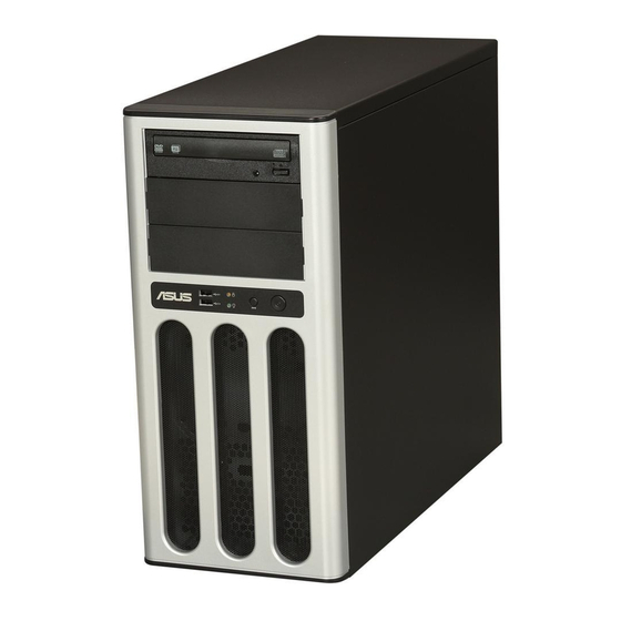
USB 2.0 ports are located on the front panel. For future installation of 5.25-inch devices, two drive bays are available. Optical drive Empty 5.25-inch bays HDD access LED Power button Reset button Power LED USB 2.0 ports Refer to section 1.7.1 Front panel LEDs for the LED descriptions. ASUS TS100-E7/PI4... -
Page 18: Rear Panel Features
Rear panel features The rear panel includes a slot for the motherboard rear I/O ports, expansion slots, a chassis lock, a vent for the system fan, and power supply module. Power connector 300W Single power supply PS/2 mouse port PS/2 keyboard port USB 2.0 ports 120mm x 25mm Serial port... -
Page 19: Internal Features
Internal features The barebone server includes the basic components as shown. Power supply unit 120mm x 25mm system fan ASUS P8B-X/MR Server Board Expansion card locks Optical drive 2 x 5.25-inch drive bays Front I/O board (hidden) Internal HDD bays Turn off the system power and detach the power supply before removing or replacing any system component. -
Page 20: Led Information
LED information 1.7.1 Front panel LEDs HDD Access LED Power LED Icon Display status Description Power LED System power ON No activity HDD Access LED Blinking Read/write data into the HDD 1.7.2 Rear panel LEDs ACT/LINK LED SPEED LED ACT/LINK LED SPEED LED ACT/LINK LED SPEED LED... - Page 21 Chapter 2 This chapter lists the hardware setup procedures that you have to perform when installing or removing system components. ASUS TS100-E7/PI4...
-
Page 22: Chapter 2: Hardware Setup
Chassis cover 2.1.1 Removing the side cover • Ensure that you unplug the power cord before removing the side cover. • Take extra care when removing the side cover. Keep your fingers from components inside the chassis that can cause injury, such as the CPU fan, rear fan, and other sharp-edged parts. -
Page 23: Reinstalling The Side Cover
Position the side cover to the chassis. Slide the side cover toward the front panel until it snaps in place. Drive in the two screws you removed earlier to secure the side cover. ASUS TS100-E7/PI4... -
Page 24: Central Processing Unit (Cpu)
ASUS will shoulder the cost of repair only if the damage is shipment/transit-related. • Keep the cap after installing the motherboard. ASUS will process Return Merchandise Authorization (RMA) requests only if the motherboard comes with the cap on the LGA1155 socket. - Page 25 CPU notches. The CPU fits in only one correct orientation. DO NOT force the Gold CPU into the socket to prevent triangle bending the connectors on the mark socket and damaging the CPU! Alignment keys ASUS TS100-E7/PI4...
- Page 26 Apply some Thermal Interface Material to the exposed area of the CPU that the heatsink will be in contact with, ensuring that it is spread in an even thin layer. Some heatsinks come with pre- applied thermal paste. If so, skip this step.
-
Page 27: Installing The Cpu Heatsink And Fan
Push down two fasteners at a time in a diagonal sequence to secure the heatsink and fan assembly in place. Orient the heatsink and fan assembly such that the CPU fan cable is closest to the CPU fan connector. ASUS TS100-E7/PI4... -
Page 28: Uninstalling The Cpu Heatsink And Fan
Connect the CPU fan cable to the connector on the motherboard labeled CPU_FAN1. DO NOT forget to connect the CPU fan connector! Hardware monitoring errors can occur if you fail to plug this connector. 2.2.3 Uninstalling the CPU heatsink and fan To uninstall the CPU heatsink and fan: Disconnect the CPU fan cable from the connector on the motherboard. -
Page 29: System Memory
Always install DIMMs with the same CAS latency. For optimum compatibility, it is recommended that you obtain memory modules from the same vendor. • Install the DDR to the A2 or B2 (orange slot) when installing only one memory module to the motherboard. ASUS TS100-E7/PI4... -
Page 30: Installing A Dimm
2.3.3 Installing a DIMM Ensure to unplug the power supply before adding or removing DIMMs or other system components. Failure to do so may cause severe damage to both the motherboard and the components. Unlock a DIMM socket by pressing DIMM notch the retaining clips outward. -
Page 31: Front Panel Cover
2.4.2 Reinstalling the front panel cover To reinstall the front panel cover: Hook the other side of the front panel cover to the chassis. Swing the front panel cover and snap it back into place. ASUS TS100-E7/PI4 2-11... -
Page 32: Inch Drives
5.25-inch drives Ensure to unplug the power cable before installing or removing any system components. Failure to do so may cause damage to the motherboard and other system components! The system comes with three 5.25-inch drive bays located on the upper front part of the chassis. - Page 33 SATA connector on the back of the drive. Connect a power plug from the power supply to the power connector on the back of the drive. Follow the instructions on the previous section to reinstall the front panel cover. ASUS TS100-E7/PI4 2-13...
-
Page 34: Hard Disk Drives
Hard disk drives The server system supports four Serial ATA hard disk drives through screw-free hard disk drive holders. To install a Serial ATA hard disk drive: Secure the supplied HDD trays to the HDD with four screws. Carefully insert the trays with the HDD installed and push them all the way to the depth of the bay. -
Page 35: Expansion Cards
Push down the expansion card lock to unlock it from the chassis. Lift up the expansion card lock as shown. Remove the metal slot cover opposite the slot where you wish to install an expansion card. ASUS TS100-E7/PI4 2-15... - Page 36 Align the card golden fingers with the slot, and then press firmly until the card is completely seated on the slot. Restore the expansion card lock to its original position. A light click indicates that the card is locked in place.
-
Page 37: Configuring An Expansion Card
ACPI Mode when used IRQ Holder for PCI Steering IRQ Holder for PCI Steering PS/2 Compatible Mouse Port Numeric Data Processor Primary IDE Channel Secondary IDE Channel * These IRQs are usually available for ISA or PCI devices. ASUS TS100-E7/PI4 2-17... -
Page 38: System Fan
System fan You may need to remove previously installed system fan when it got defective. This section tells how to remove the system fan. To remove the system fan: Unplug the system fan cable from the REAR_FAN1 connector on the motherboard. -
Page 39: Cable Connections
8-pin ATX 12V power connector (from power supply to motherboard) System fan connector (from system fan to motherboard) SATA conectors (system default; from motherboard to SATA devices) USB connector (from motherboard to front I/O board) System panel connector (from motherboard to front I/O board) ASUS TS100-E7/PI4 2-19... - Page 40 2-20 Chapter 2: Hardware setup...
- Page 41 Chapter 3 This chapter includes the motherboard layout and brief descriptions of the jumpers and internal connectors. ASUS TS100-E7/PI4...
-
Page 42: Chapter 3: Motherboard Info
Motherboard layout Chapter 3: Motherboard information... -
Page 43: Layout Contents
Serial General Purpose Input/Output connector (6-1 pin SGPIO1) 3-12 Serial port connectors (10-1 pin COM2) 3-12 TPM connector (20-1-pin TPM) 3-13 ATX power connectors (24-pin EATXPWR1, 8-pin EATX12V1) 3-14 System panel connector (20-1 pin PANEL1) 3-15 Auxiliary panel connector (20-2 pin AUX_PANEL1) 3-16 ASUS TS100-E7/PI4... -
Page 44: Jumpers
Jumpers Clear RTC RAM (CLRTC1) This jumper allows you to clear the Real Time Clock (RTC) RAM in CMOS. You can clear the CMOS memory of date, time, and system setup parameters by erasing the CMOS RTC RAM data. The onboard button cell battery powers the RAM data in CMOS, which include system setup information such as system passwords. - Page 45 If you use a 4-pin fan but set the jumper to pin 2-3, the fan you installed may not work. • If you use a 3-pin fan but set the jumper for a 4-pin fan, the fan control will not work and the fan you installed will always run at full speed. ASUS TS100-E7/PI4...
- Page 46 LAN controller setting (3-pin LAN_SW1, LAN_SW2) These jumpers allow you to enable or disable the onboard Intel 82574L ® Gigabit LAN controllers. Set to pins 1-2 to activate the Gigabit LAN feature. Intel C202 SATA port S/W RAID setting (3-pin RAID_SEL1) ®...
-
Page 47: Internal Connectors
If you installed Serial ATA hard disk drives, you can create a RAID 0, RAID 1, RAID 10, or RAID 5 configuration. The actual data transfer rate depends on the speed of Serial ATA hard disks installed. ASUS TS100-E7/PI4... - Page 48 Hard disk activity LED connector (4-pin HDLED1) This LED connector is for the storage add-on card cable connected to the SATA or SAS add-on card. The read or write activities of any device connected to the SATA or SAS add-on card causes the front panel LED to light up.
- Page 49 480 Mbps connection speed. Thermal sensor cable connectors (3-pin TR1) This connector is for temperature monitoring. Connect the thermal sensor cable to this connector and place the other end to the device, which you want to monitor temperature. ASUS TS100-E7/PI4...
- Page 50 DO NOT forget to connect the fan cables to the fan connectors. Insufficient air flow inside the system may damage the motherboard components. • These are not jumpers! DO NOT place jumper caps on the fan connectors! • All fans feature the ASUS Smart Fan technology. 3-10 Chapter 3: Motherboard information...
- Page 51 Serial port connectors (10-1 pin COM2) This connector is for the serial (COM) port. Connect the serial port module cable to one of these connectors, then install the module to a slot opening at the back of the system chassis. ASUS TS100-E7/PI4 3-11...
- Page 52 TPM connector (20-1 pin TPM) This connector supports a Trusted Platform Module (TPM) system, which can securely store keys, digital certificates, passwords, and data. A TPM system also helps enhance network security, protects digital identities, and ensures platform integrity. 3-12 Chapter 3: Motherboard information...
- Page 53 • This motherboard supports ATX2.0 PSU or later version. • Ensure that your power supply unit (PSU) can provide at least the minimum power required by your system. ASUS TS100-E7/PI4 3-13...
- Page 54 10. System panel connector (20-pin PANEL1) This connector supports several chassis-mounted functions. System power LED (3-pin PLED) This 3-pin connector is for the system power LED. Connect the chassis power LED cable to this connector. The system power LED lights up when you turn on the system power, and blinks when the system is in sleep mode.
- Page 55 Connect the Locator LED cables to these 2-pin connector. The LEDs will light up when the Locator button is pressed. Locator Button/Swich (2-pin LOCATORBTN) These leads are for the locator button on the front panel. This button queries the state of the system locator. ASUS TS100-E7/PI4 3-15...
- Page 56 3-16 Chapter 3: Motherboard information...
- Page 57 Chapter 4 This chapter tells how to change the system settings through the BIOS Setup menus. Detailed descriptions of the BIOS parameters are also provided. ASUS TS100-E7/PI4...
-
Page 58: Chapter 4: Bios Setup
4.1.1 ASUS CrashFree BIOS 3 utility The ASUS CrashFree BIOS 3 is an auto recovery tool that allows you to restore the BIOS file when it fails or gets corrupted during the updating process. You can update a corrupted BIOS file using a USB flash drive that contains the updated BIOS file. -
Page 59: Asus Ez Flash Utility
4.1.2 ASUS EZ Flash Utility The ASUS EZ Flash Utility feature allows you to update the BIOS without having to use a DOS-based utility. Before you start using this utility, download the latest BIOS from the ASUS website at www.asus.com. -
Page 60: Bupdater Utility
Updating the BIOS file To update the BIOS file using the BUPDATER utility: Visit the ASUS website at www.asus.com and download the latest BIOS file for the motherboard. Save the BIOS file to a bootable USB flash disk drive. Copy the BUPDATER utility (BUPDATER.exe) from the ASUS support website at support.asus.com to the bootable USB flash disk drive you created... - Page 61 DO NOT shut down or reset the system while updating the BIOS to prevent system boot failure! The utility returns to the DOS prompt after the BIOS update process is completed. Reboot the system from the hard disk drive. The BIOS update is finished! Please restart your system. C:\> ASUS TS100-E7/PI4...
-
Page 62: Bios Setup Program
The BIOS setup screens shown in this section are for reference purposes only, and may not exactly match what you see on your screen. • Visit the ASUS website (www.asus.com) to download the latest BIOS file for this motherboard. Chapter 4: BIOS setup... -
Page 63: Bios Menu Screen
For changing the system boot configuration Tool For configuring options for special functions Exit For selecting the exit options To select an item on the menu bar, press the right or left arrow key on the keyboard until the desired item is highlighted. ASUS TS100-E7/PI4... -
Page 64: Menu Items
4.2.3 Menu items The highlighted item on the menu bar displays the specific items for that menu. For example, selecting Main shows the Main menu items. The other items (Event Logs, Advanced, Monitor, Boot, Tool, and Exit) on the menu bar have their respective menu items. -
Page 65: Main Menu
Clock (RTC) RAM to clear the BIOS password. See section 2.6 Jumpers for information on how to erase the RTC RAM. The Administrator or User Password items on top of the screen show • the default Not Installed. After you set a password, these items show Installed. ASUS TS100-E7/PI4... -
Page 66: Administrator Password
Administrator Password If you have set an administrator password, we recommend that you enter the administrator password for accessing the system. Otherwise, you might be able to see or change only selected fields in the BIOS setup program. To set an administrator password: Select the Administrator Password item and press <Enter>. -
Page 67: Event Logs Menu
Allows you to adjust value for the METW (Multiple Event Time Window), which is the number of minutes that must pass between duplicate log entries which utilize a multiple-event counter. Use the <+> and <-> keys to adjust the value. The values range from 0 to 99. ASUS TS100-E7/PI4 4-11... - Page 68 Log OEM Codes [Enabled] Allows you to enable or disable the logging of EFI status codes as OEM codes. Configuration option: [Disabled] [Enabled] Convert OEM Codes [Disabled] Allows you to enable or disable the converting of EFI status codes to standard Smbios types.
-
Page 69: Advanced Menu
Allows you to enable or disable ACPI Auto Configuration. Configuration options: [Disabled] [Enabled] ACPI Sleep State [S3 (Suspend to RAM)] Allows you to set the ACPI Sleep State. Configuration options: [Suspend Disabled] [S1 (CPU Stop Clock)] [S3 (Suspend to RAM)] ASUS TS100-E7/PI4 4-13... -
Page 70: Trusted Computing
4.5.2 Trusted Computing Aptio Setup Utility - Copyright (C) 2010 American Megatrends, Inc. Advanced Enables or Disables TPM TPM Configuration support. O.S. will not show TPM SUPPORT [Disabled] TPM. Reset of platform is required. Current TPM Status Information NO TPM Hardware TPM SUPPORT [Disabled] Allows you to enable or disable the TPM support. -
Page 71: Cpu Configuration
Allows you to choose the number of CPU cores to activate in each processor package. Configuration options: [All] [1] [2] [3] Limit CPUID Maximum [Disabled] Setting this item to [Enabled] allows legacy operating systems to boot even without support for CPUs with extended CPUID functions. Configuration options: [Disabled] [Enabled] ASUS TS100-E7/PI4 4-15... - Page 72 Execute Disable Bit [Enabled] Allows you to enable or disable the No-Execution Page Protection Technology. Setting this item to [Disabled] forces the XD feature flag to always return to zero (0). Configuration options: [Disabled] [Enabled] Intel Virtualization Tech [Enabled] The Intel ®...
-
Page 73: North Bridge
Enabled/disabled the High SB Chipset Configuration Precision Event Timer. High Precision Event Timer Configuration High Precision Timer [Enabled] High Precision Timer [Enabled] Allows you to enable or disable the High Precision Event Timer. Configuration options: [Enabled] [Disabled] ASUS TS100-E7/PI4 4-17... -
Page 74: Sata Configuration
[Enhanced] S.M.A.R.T. Status Check [Enabled] SATA Port1 ST3160812AS (160.0GB) SATA Port2 ST3160812AS (160.0GB) SATA Port3 ASUS CB-521 ATAPI SATA Port4 Not Present SATA Port5 Not Present SATA Port6 Not Present SATA Mode [IDE Mode] Allows you to set the SATA configuration. -
Page 75: Intel Txt(Lt) Configuration
USB controller legacy mode is enabled. If no USB device is detected, the legacy USB support is disabled. Configuration options: [Disabled] [Enabled] [Auto] EHCI Hand-off [Disabled] Enables or disables the BIOS EHCI hand-off support. Configuration options: [Disabled] [Enabled] ASUS TS100-E7/PI4 4-19... -
Page 76: Onboard Devices Configuration
USB transfer time-out [20 sec] Allows you to select the USB transfer time-out value. Configuration options: [1 sec] [5 sec] [10 sec] [20 sec] Device reset time-out [20 sec] Allows you to select the USB device reset time-out value. Configuration options: [10 sec] [20 sec] [30 sec] [40 sec] Device power-up delay [Auto] Configuration options: [Auto] [Manual] Device power-up delay in seconds [XX]... - Page 77 Device Mode [STD Printer Mode] Allows you to select the printer port mode. Configuration options: [STD Printer mode] [SPP Mode] [EPP-1.9 and SPP Mode] [EPP-1.7 and SPP Mode] [ECP Mode] [ECP and EPP 1.9 Mode] [ECP and EPP 1.7 Mode] ASUS TS100-E7/PI4 4-21...
-
Page 78: Apm
4.5.11 Aptio Setup Utility - Copyright (C) 2010 American Megatrends, Inc. Advanced Specify what state to go to Restrore AC Power Loss [Power Off] when power is re-applied after EuP Ready [Disabled] a power failure (G3 state). Power On By PCI [Disabled] Power On By PCIE [Disabled]... -
Page 79: Serial Port Console Redirection
0 if the num of 1’s in the data bits is even [Odd] parity bit is 0 if num of 1’s in the data bits is odd [Mark] parity bit is always 1 [Space] parity bit is always 0 ASUS TS100-E7/PI4 4-23... -
Page 80: Console Redirection Settings
Stop Bits [1] Stop bits indicate the end of a serial data packet. (A start bit indicates the beginning.) The standard setting is 1 stop bit. Communication with slow devices may require more than 1 stop bit. Configuration options: [1] [2] Flow Control [Hardware RTS/CTS] Flow control can prevent data loss from buffer overflow. -
Page 81: Monitor Menu
N/A. Fan Speed Control [Generic Mode] Allows you to configure the ASUS Smart Fan feature that smartly adjusts the fan speeds for more efficient system operation. Configuration options: [Full Speed Mode] [High Density Mode] [Generic Mode] [Whisper Mode] VCORE1 Voltage, 3.3V Voltage, +5V Voltage, +12V Voltage,... -
Page 82: Boot Menu
Allows you to enable or disable the full screen logo display feature. Configuration options: [Disabled] [Enabled] Set this item to [Enabled] to use the ASUS MyLogo2™ feature. Option ROM Messages [Force BIOS] Allows you to set the display mode for Options ROM. -
Page 83: Network Device Bbs Priorities
The number of device items that appears on the screen depends on the number of devices installed in the system. • To select the boot device during system startup, press <F8> when ASUS Logo appears. • To access Windows OS in Safe Mode, do any of the following: - Press <F5>... -
Page 84: Tool Menu
Be used to update BIOS ASUS EZ Flash Utility ASUS EZ Flash Utility Allows you to run ASUS EZ Flash 2. When you press <Enter>. Check section 4.1.2 ASUS EZ Flash 2 utility for details. Exit menu The Exit menu items allow you to save or discard your changes to the BIOS items. - Page 85 Chapter 5 This chapter provides instructions for setting up, creating and configuring RAID sets using the available utilities. ASUS TS100-E7/PI4...
-
Page 86: Chapter 5: Raid Configuration
Setting up RAID The motherboard comes with the Intel C202 southbridge controller that supports ® the following SATA RAID solutions: LSI MegaRAID software RAID Configuration Utility (default) with RAID 0, • RAID 1, and RAID 10 support (for both Linux and Windows OS). Intel Rapid Storage Manager with RAID 0, RAID 1, RAID 10, and RAID 5 •... -
Page 87: Installing Hard Disk Drives
Go to the Main menu > Storage Configuration, and then press <Enter>. Set the Configure SATA as item to [RAID]. Save your changes, and then exit the BIOS Setup. Refer to Chapter 4 for details on entering and navigating through the BIOS Setup. ASUS TS100-E7/PI4... -
Page 88: L Si Software Raid Configuration Utility
5.2 L SI Software RAID Configuration Utility The LSI MegaRAID software RAID configuration utility allows you to create RAID 0, RAID 1, or RAID 10 set(s) from SATA hard disk drives connected to the SATA connectors supported by the motherboard southbridge chip. To enter the LSI MegaRAID software RAID configuration utility Turn on the system after installing all the SATA hard disk drives. -
Page 89: Creating A Raid Set
Management Menu View/Add Configuration Configure Clear Configuration Initialize Select Boot Drive Objects Rebuild Check Consistency Defines Physical Arrays. An Array Will Automatically Become A VD Use Cursor Keys to Navigate Between Items And Press Enter To Select An Option ASUS TS100-E7/PI4... - Page 90 The ARRAY SELECTION MENU displays the available drives connected to the SATA ports. Use the up/down arrow key to select the drives you want to include in the RAID set, and then press <Space>. When selected, the drive indicator changes from READY to ONLIN A[X]-[Y], where X is the array number, and Y is the drive number.
- Page 91 Check Consistency Virtual Drive 0 RAID Level RAID = 1 RAID 0 Size = 77247MB RAID 1 DWC = Off = On Accept SPAN = NO Choose RAID Level For This VD Cursor Keys, SPACE-(De)Select F2-ChIdInfo F3-SlotInfo F10-Configure Esc-Quit ASUS TS100-E7/PI4...
- Page 92 When creating a RAID 1 or a RAID 10 set, select DWC from the Virtual Drive menu, and then press <Enter>. When creating a RAID 0 set, proceed to step 10. Select On to enable the Disk Write Cache setting, and then press <Enter>. LSI Software RAID Configuration Utility Ver A.62 Apr 29, 2009 BIOS Version A.09.07211059R...
- Page 93 New Configuration Management Menu Configure View/Add Configuration Initialize Clear Configuration Select Boot Drive Objects Rebuild Check Consistency Clear Existing Configuration And Start A New Configuration Use Cursor Keys to Navigate Between Items And Press Enter To Select An Option ASUS TS100-E7/PI4...
- Page 94 Follow step 2 to 7 of the previous section: Using Easy Configuration. Select Size from the Virtual Drive menu, and then press <Enter>. Key-in the desired virtual drive size, and then press <Enter>. LSI Software RAID Configuration Utility Ver A.62 Apr 29, 2009 BIOS Version A.09.07211059R Virtual Drive(s) Configured...
-
Page 95: Adding Or Viewing A Raid Configuration
SPACE-Sel,ENTER-EndArray,F10-Configure,F2-Drive Info,F3-Virtual Drives,F4-HSP The information of the selected hard disk drive displays at the bottom of the screen. Follow step 3 to 12 of section 6.2.1 Creating a RAID set: Using Easy Configuration to add a new RAID set. ASUS TS100-E7/PI4 5-11... -
Page 96: Initializing The Virtual Drives
5.2.3 Initializing the virtual drives After creating the RAID set(s), you must initialize the virtual drives. You may initialize the virtual drives of a RAID set(s) using the Initialize or Objects command on the Management Menu. Using the Initialize command To initialize the virtual drive using the Initialize command From the Management Menu, select Initialize, and then press <Enter>. - Page 97 RAID Size #Stripes StripSz Status Configure 154494MB 64 KB ONLINE Init Of VD Is In Process Initialize Objects VD 0 Initialization Complete. Press Esc.. Rebuild Check Consistency ¦ 100% Completed Virtual Drives Virtual Drive 0 SPACE-(De)Select, F10-Initialize ASUS TS100-E7/PI4 5-13...
- Page 98 Using the Objects command To initialize the virtual drives using the Objects command From the Management Menu, select Objects > Virtual Drive, and then press <Enter>. LSI Software RAID Configuration Utility Ver A.62 Apr 29, 2009 BIOS Version A.09.07211059R Objects Management Menu Adapter Configure Virtual Drive Initialize Physical Drive Objects...
- Page 99 Initilize Will Destroy Data On Selected VD(s) Use Cursor Keys To Navigate Between Items And Press Enter To Select An Option A progress bar appears on screen. If desired, press <Esc> to abort initialization. When initialization is completed, press <Esc>. ASUS TS100-E7/PI4 5-15...
-
Page 100: Rebuilding Failed Drives
5.2.4 Rebuilding failed drives You can manually rebuild failed hard disk drives using the Rebuild command in the Management Menu. To rebuild a failed hard disk drive From the Management Menu, select Rebuild, and then press <Enter>. LSI Software RAID Configuration Utility Ver A.62 Apr 29, 2009 BIOS Version A.09.07211059R Management Menu... - Page 101 RBLD A00-01 Rebuild Check Consistency Rebuilding Of Drive Will Take A Few Minutes. Start Rebuilding Drive (Y/N)? Port # 1 DISK 77247MB HDS728080PLA380 PF20A60A SPACE-(De)Select,F10-Start Rebuild,F2-Drive Information,F3-View Virtual Drives When rebuild is complete, press any key to continue. ASUS TS100-E7/PI4 5-17...
-
Page 102: Checking The Drives For Data Consistency
5.2.5 Checking the drives for data consistency You can check and verify the accuracy of data redundancy in the selected virtual drive. The utility can automatically detect and/or detect and correct any differences in data redundancy depending on the selected option in the Objects > Adapter menu. - Page 103 • Continue - Continues the consistency check. • Abort - Aborts the consistency check. When you restart checking, it continues from zero percent. When checking is complete, press any key to continue. ASUS TS100-E7/PI4 5-19...
- Page 104 Using the Objects command To check data consistency using the Objects command From the Management Menu, select Objects, and then select Virtual Drive from the sub-menu. Use the arrow keys to select the virtual drive you want to check, and then press <Enter>. Select Check Consistency from the pop-up menu, and then press <Enter>.
-
Page 105: Deleting A Raid Configuration
Initialize Select Boot Drive Objects Rebuild Check Consistency Clear Existing Configuration Use Cursor Keys To Navigate Between Items And Press Enter To Select An Option The utility clears all the current array(s). Press any key to continue. ASUS TS100-E7/PI4 5-21... -
Page 106: Selecting The Boot Drive From A Raid Set
5.2.7 Selecting the boot drive from a RAID set You must have created a new RAID configuration before you can select the boot drive from a RAID set. See section 5.2.1 Creating a RAID set: Using New Configuration for details. To select the boot drive from a RAID set From the Management Menu, select Configure >... -
Page 107: Enabling Writecache
= On Check Consistency Read Ahead = On Disk Write Cache - Off(Write Through) or On(Write Back) Use Cursor Keys To Navigate Between Items And Press Enter To Select An Option When finished, press any key to continue. ASUS TS100-E7/PI4 5-23... -
Page 108: Intel ® Rapid Storage Technology Option Rom Utilitys
® Intel Rapid Storage Technology Option ROM Utilitys The Intel ® Rapid Storage Technology Option ROM utility allows you to create RAID 0, RAID 1, RAID 10 (RAID 1+0), and RAID 5 set(s) from Serial ATA hard disk drives that are connected to the Serial ATA connectors supported by the Southbridge. To enter the Intel ®... -
Page 109: Creating A Raid Set
Select 2 to 6 disks to use in creating the volume. [ ↑↓ ]-Prev/Next [SPACE]-SelectDisk [ENTER]-Done Use the up/down arrow keys to select a drive, and then press <Space> to select. A small triangle marks the selected drive. Press <Enter> after completing your selection. ASUS TS100-E7/PI4 5-25... -
Page 110: Creating A Recovery Set
Use the up/down arrow keys to select the stripe size for the RAID array (for RAID 0, 10 and 5 only), and then press <Enter>. The available stripe size values range from 4 KB to 128 KB. The following are typical values: RAID 0: 128KB RAID 10: 64KB RAID 5: 64KB... - Page 111 Press <Y> to create the recovery set and return to the main menu, or <N> to go back to the CREATE VOLUME menu. If a recovery set is created, you cannot add more RAID sets even when you have more non-RAID disks installed in your system. ASUS TS100-E7/PI4 5-27...
-
Page 112: Deleting A Raid Set
5.3.3 Deleting a RAID set Take caution when deleting a RAID set. You will lose all data on the hard disk drives when you delete a RAID set. To delete a RAID set: From the utility main menu, select 2. Delete RAID Volume and press <Enter>. -
Page 113: Resetting Disks To Non-Raid
Use the up/down arrow keys to select the RAID set drive(s) you want to reset, and then press <Space> to select. Press <Enter> to reset the RAID set drive(s). A confirmation message appears. Press <Y> to reset the drive(s) or press <N> to return to the utility main menu. ASUS TS100-E7/PI4 5-29... -
Page 114: Recovery Volume Options
5.3.5 Recovery Volume Options If you have created a recovery set, you can configure more recovery set options following the descriptions in the section. See section 5.3.2 Creating a Recovery set to create a recovery set before continue. To configure a recovery set: From the utility main menu, select 4. -
Page 115: Exiting The Intel ® Rapid Storage Technology Utility
Select the port of destination disk for rebuilding (ESC to exit): Port Drive Model Serial # Size XXXXXXXXXXX XXXXXXXX XX.XGB [ ↑↓ ]-Previous/Next [ENTER]-Select [ESC]-Exit Select a destination disk with the same size as the original hard disk. ASUS TS100-E7/PI4 5-31... -
Page 116: Rebuilding The Raid With A New Hard Disk
The utility immediately starts rebuilding after the disk is selected. The status of the degraded RAID volume is changed to “Rebuild”. Intel(R) Rapid Storage Technology - Option ROM - 10.1.0.1008 Copyright(C) 2003-10 Intel Corporation. All Rights Reserved. MAIN MENU 1. Create RAID Volume 3. -
Page 117: Setting The Boot Array In The Bios Setup Utility
Use up/down arrow keys to select the boot priority and press <Enter>. See section 4.7 Boot menu for details. From the Exit menu, select Save Changes & Exit, then press <Enter>. When the confirmation window appears, select Yes, then press <Enter>. ASUS TS100-E7/PI4 5-33... - Page 118 5-34 Chapter 5: RAID configuration...
- Page 119 Chapter 6 This chapter provides instructions for installing the necessary drivers for different system components. ASUS TS100-E7/PI4...
-
Page 120: Chapter 6: Driver Installation
RAID driver installation After creating the RAID sets for your server system, you are now ready to install an operating system to the independent hard disk drive or bootable array. This part provides instructions on how to install the RAID controller drivers during OS installation. - Page 121 SLES 10 SP3 32 bit SLES 10 SP3 64 bit SLES 11 32 bit Locate the RAID driver and place a blank, high-density floppy disk to the floppy disk drive. Press <Enter>. Follow screen instructions to create the driver disk. ASUS TS100-E7/PI4...
- Page 122 To create a RAID driver disk in Windows environment ® Start Windows ® Place the motherboard support DVD into the optical drive. Go to the Make Disk menu, and then select the type of RAID driver disk you want to create. Insert a floppy disk into the floppy disk drive.
-
Page 123: Installing The Raid Controller Driver
S. * If you do not have any device support disks from a mass storage device manufacturer, or do not want to specify additional mass storage devices for use with Windows, press ENTER. S=Specify Additional Device ENTER=Continue F3=Exit ASUS TS100-E7/PI4... - Page 124 Insert the RAID driver disk you created earlier to the USB floppy disk drive, then press <Enter>. Windows Setup Please insert the disk labeled Manufacturer-supplied hardware support disk into Drive A: Press ENTER when ready. ENTER=Continue ESC=Cancel F3=Exit Select the RAID controller driver you need from the list, then press <Enter>. The Windows ®...
- Page 125 The screen differs based on the controller. Right-click the RAID controller driver item, and then select Properties from the menu. Click the Driver tab, and then click the Driver Details button to display the RAID controller drivers. Click OK when finished. ASUS TS100-E7/PI4...
-
Page 126: Intel ® Chipset Device Software Installation
® Intel chipset device software installation This section provides the instructions on how to install the Intel ® chipset device software on the system. You need to manually install the Intel chipset device software on a Windows ® operating system. To install the Intel ®... - Page 127 Select Yes to accept the terms of the License Agreement and continue the process. Read the Readme File Information and press Next to continue the installation. After completing the installation, click Finish to complete the setup process. ASUS TS100-E7/PI4...
-
Page 128: Lan Driver Installation
LAN driver installation This section provides the instructions on how to install the Intel Gigabit LAN ® controller drivers on the system. You need to manually install the LAN controller driver on a Windows ® operating system. To install the LAN controller drivers: Restart the computer, and then log on with Administrator privileges. - Page 129 Click Next when the Intel(R) Network Connections–InstallShield Wizard window appears. Toggle I accept the terms in the license agreement and click Next to continue. Click the Intel(R) PROSet for Windows Device Manager box, and then click Next to start the installation. ASUS TS100-E7/PI4 6-11...
- Page 130 Follow the screen instructions to complete installation. When finished, press Finish to continue. 6-12 Chapter 6: Driver installation...
-
Page 131: Vga Driver Installation
DVD to locate the file ASSETUP.EXE from the BIN folder. Double-click the ASSETUP.EXE to run the support DVD. Click on the ASPEED AST1100 Display Driver to begin installation. When the ASPEED Graphics installation wizard window appears, click Next to start the installation. ASUS TS100-E7/PI4 6-13... - Page 132 To allow the system to update the VGA driver, follow the steps shown in the next few windows, and click Next when finished. a. Accept the terms in the license agreement. b. Fill in User Name and Organization. (optional) c. Select a setup type. Click Install to begin the installation.
-
Page 133: Management Applications And Utilities Installation
The contents of the support DVD are subject to change at any time without notice. Visit the ASUS website (www.asus.com) for updates. 6.5.1 Running the support DVD Place the support DVD to the optical drive. -
Page 134: Utilities Menu
Intel and LSI MegaRAID driver disks. 6.5.5 Contact information Click the Contact tab to display the ASUS contact information. You can also find this information on the inside front cover of this user guide. 6-16 Chapter 6: Driver installation... -
Page 135: Asus Contact Information
ASUS contact information ASUSTeK COMPUTER INC. Address 15 Li-Te Road, Peitou, Taipei, Taiwan 11259 Telephone +886-2-2894-3447 +886-2-2890-7798 E-mail info@asus.com.tw Web site http://www.asus.com.tw Technical Support Telephone +86-21-38429911 +86-21-58668722 ext: 9101 Online Support http://support.asus.com/techserv/techserv.aspx ASUSTeK COMPUTER INC. (Taiwan) Address 15 Li-Te Road, Peitou, Taipei, Taiwan 11259... - Page 136 800 Corporate Way, Fremont, CA 94539, USA +1-510-608-4555 Web site http://usa.asus.com Technical Support Support fax +1-812-284-0883 General support +1-812-282-2787 Online support http://support.asus.com/techserv/techserv.aspx ASUS COMPUTER GmbH (Germany and Austria) Address Harkort Str. 21-23, 40880 Ratingen, Germany +49-2102-959911 Web site http://www.asus.de Online contact http://www.asus.de/sales Technical Support Telephone +49-1805-010923...
Need help?
Do you have a question about the TS100-E7/PI4 and is the answer not in the manual?
Questions and answers