Table of Contents
Advertisement
Quick Links
Advertisement
Table of Contents

Related Manuals for Asus TS300-E9-PS4


Summary of Contents for Asus TS300-E9-PS4
- Page 1 TS300-E9-PS4 Server User Guide...
- Page 2 ASUSTeK COMPUTER INC. (“ASUS”). ASUS provides this manual “as is” without warranty of any kind, either express or implied, including but not limited to the implied warranties or conditions of merchantability or fitness for a particular purpose. In no...
-
Page 3: Table Of Contents
Contents Notices ........................vii Safety information ....................viii About this guide ......................x Chapter 1: Product Introduction System package contents ................. 1-2 Serial number label ..................1-3 System specifications ................1-4 Front panel features ................... 1-6 Rear panel features ..................1-7 Internal features .................. - Page 4 Installing a 5.25-inch drive ............2-18 Expansion slots ..................2-19 2.7.1 Installing an expansion card............2-19 2.7.2 Installing an ASUS PIKE II card ..........2-21 2.7.3 Configuring an expansion card ..........2-23 2.7.4 Installing an M.2 expansion card..........2-25 Cable connections ................... 2-26 2.8.1...
- Page 5 Contents BIOS setup program .................. 5-6 5.2.1 BIOS menu screen ..............5-7 5.2.2 Menu bar ..................5-7 5.2.3 Menu items.................. 5-8 5.2.4 Submenu items ................5-8 5.2.5 Navigation keys ................5-8 5.2.6 General help................5-8 5.2.7 Configuration fields ..............5-8 5.2.8 Pop-up window................
- Page 6 Running the Support DVD ................. 7-4 ® Installing the Intel Chipset device Software driver ....... 7-7 ® Installing the Intel I210 Gigabit Adapters driver ........7-10 Installing the VGA driver ................. 7-13 Appendix P10S-E/4L block diagram ..................A-2 ASUS contact information ..................A-3...
-
Page 7: Notices
Radio Interference Regulations of the Canadian Department of Communications. This Class A digital apparatus complies with Canadian ICES-003. REACH Complying with the REACH (Registration, Evaluation, Authorization, and Restriction of Chemicals) regulatory framework, we publish the chemical substances in our products at ASUS REACH website at http://csr.asus.com/english/REACH.htm. -
Page 8: Safety Information
Safety information Electrical Safety • Before installing or removing signal cables, ensure that the power cables for the system unit and all attached devices are unplugged. • To prevent electrical shock hazard, disconnect the power cable from the electrical outlet before relocating the system. - Page 9 If you require assistance please call ASUS Customer Service 1300 2787 88 or visit us at https://www.asus.com/support.
-
Page 10: About This Guide
About this guide Audience This user guide is intended for system integrators, and experienced users with at least basic knowledge of configuring a server. Contents This guide contains the following parts: Chapter 1: Product Introduction This chapter describes the general features of the server, including sections on front panel and rear panel specifications. - Page 11 Refer to the following sources for additional information, and for product and software updates. ASUS Server Web-based Management (ASWM) user guide This manual tells how to set up and use the proprietary ASUS server management utility. ASUS websites The ASUS websites worldwide provide updated information for all ASUS hardware and...
-
Page 13: Chapter 1: Product Introduction
Chapter 1: Product Introduction Product Introduction This chapter describes the motherboard features and the new technologies it supports. -
Page 14: System Package Contents
System package contents Check your system package for the following items. Model Name TS300-E9-PS4 Chassis ASUS T50D Pedestal / 5U Rackmount Chassis Motherboard ASUS P10S-E/4L Server Board 1 x 500W (80Plus) Bronze Single Power Supply 4 x Hot-swap HDD trays*... -
Page 15: Serial Number Label
Serial number label Before requesting support from the ASUS Technical Support team, you must take note of the product’s serial number containing 12 characters such as xxS0xxxxxxxx shown as the figure below. With the correct serial number of the product, ASUS Technical Support team members can then offer a quicker and satisfying solution to your problems. -
Page 16: System Specifications
System specifications The ASUS TS300-E9-PS4 is a Pedestal / 5U Rackmount barebone server system featuring ® ® ® the ASUS P10S-E/4L Server Board. The server supports Intel LGA1151 Intel Xeon 1200 Processor v5 plus other latest technologies through the chipsets onboard. - Page 17 ® SuSE Linux Enterprise Server OS Support CentOS VMware Citrix XenServer * Support versions are subject to change without notice. Refer to www.asus.com for updates. ASWM Enterprise Software Management Out of Band Solution Remote Optional ASMB8-iKVM for KVM-over-IP support Management Dimensions (HH x WW x DD) 455mm x 217.5mm x 545mm...
-
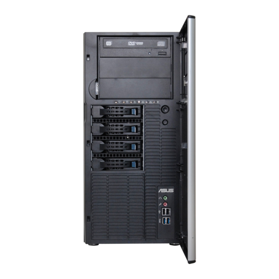
Page 18: Front Panel Features
Front panel features Message LED LAN1/3 LED LAN2/4 LED HDD access LED Location LED Power LED (Reserved) Optical drive (optional) 2 x Empty 5.25-inch bays Security lock Power button Reset button 4-bay HDD module Headphone jack** 4-bay HDD module (optional*) Microphone jack** 2 x USB 2.0 ports 2 x USB 3.0 ports... -
Page 19: Rear Panel Features
2 x USB 3.0 ports Management LAN port* VGA port LAN (RJ-45) port 1-4 COM port Expansion slots This port is for ASUS ASMB8-iKVM controller and for technicians only. LAN port 1 LAN port 1 LAN port 1 LAN port 1 LAN port 1 這邊編號我不太清楚... -
Page 20: Internal Features
Internal features The barebone server includes the basic components as shown. 500W 80 PLUS Bronze Power Supply 120mm x 38mm system fan ASUS P10S-E/4L Server Board Chassis intrusion switch Expansion card locks Optical drive (optional) 2 x 5.25-inch drive bays... -
Page 21: Led Information
HDD rebuilding using the RAID card Blinking No LAN connection LAN LEDs Blinking LAN is transmitting or receiving data LAN connection is present The Power LED, HDD Status LED and Message LED are visible even if the system front bezel is closed. ASUS TS300-E9-PS4... -
Page 22: Lan (Rj-45) Leds
1.7.2 LAN (RJ-45) LEDs ACT/LINK LED SPEED LED ACT/LINK LED SPEED LED ACT/LINK LED SPEED LED ACT/LINK LED SPEED LED ACT/LINK LED SPEED LED Status Description Status Description No link 10 Mbps connection ORANGE Linked ORANGE 100 Mbps connection BLINKING Data activity GREEN 1 Gbps connection... -
Page 23: Chapter 2: Hardware Information
Chapter 2: Hardware Information Hardware Information This chapter lists the hardware setup procedures that you have to perform when installing or removing system components. -
Page 24: Chassis Cover
Chassis cover 2.1.1 Removing the side cover • Ensure that you unplug the power cord before removing the side cover. • Take extra care when removing the side cover. Keep your fingers from components inside the chassis that can cause injury, such as the CPU fan, rear fan, and other sharp-edged parts. To remove the side cover: Remove the two screws that secure the side cover. Slide the side cover for about half an inch toward the rear until it is disengaged from the chassis. -
Page 25: Reinstalling The Side Cover
Match and insert the lower sliding edge of the side cover to the corresponding chassis edge. Slide the side cover toward the front panel until it snaps in place. Drive in the two screws you removed earlier to secure the side cover. ASUS TS300-E9-PS4... -
Page 26: Central Processing Unit (Cpu)
Central Processing Unit (CPU) The motherboard comes with two surface mount LGA 1151 sockets designed for the Intel ® Xeon E3-1200 v5 family processor. • Upon purchase of the motherboard, ensure that the PnP cap is on the socket and the socket contacts are not bent. Contact your retailer immediately if the PnP cap is missing, or if you see any damage to the PnP cap/socket contacts/motherboard components. • Keep the cap after installing the motherboard. ASUS will process Return Merchandise Authorization (RMA) requests only if the motherboard comes with the cap on the LGA 1151 socket. • The product warranty does not cover damage to the socket contacts resulting from incorrect CPU installation/removal, or misplacement/loss/incorrect removal of the PnP cap. 2.2.1 Installing the CPU To install a CPU: Locate the CPU socket on the motherboard. - Page 27 Retention tab Lift the load lever until the load plate is completely lifted. Load plate Position the CPU above the socket, ensuring that the gold triangle mark is on the bottom-left corner of the socket, then fit the CPU notches to the socket's CPU notches alignment keys. The CPU fits in only one orientation. DO NOT force the CPU into the socket to prevent bending the pins on Gold Alignment triangle the socket and damaging the CPU. mark Alignment ASUS TS300-E9-PS4...
- Page 28 Close the load plate (A), ensuring that the front edge of the load plate slides Load lever under the retention lock (B) then push down the load lever (C). Retention lock Insert the load lever under the retention tab to remove the PnP cap from the CPU socket. Load lever Retention tab Apply some Thermal Interface Material to the exposed area of the CPU that the heatsink will be in contact with, ensuring that it is evenly spread in a thin layer. Some heatsinks come with pre-applied Thermal Interface Material. If so, skip this step.
-
Page 29: Installing The Cpu Heatsink
• When you buy a boxed Intel processor, a specially designed CPU heatsink or a CPU heatsink with a CPU fan assembly is included depending on the package. If you ® buy a CPU separately, ensure that you use only Intel certified multi-directional CPU heatsink or CPU heatsink with CPU fan. • Use an LGA1151-compatible CPU heatsink and CPU fan assembly only. The LGA1151 socket is incompatible with the LGA775 and LGA1366 sockets in size and dimension. If you purchased a separate CPU heatsink and fan assembly, ensure that the Thermal Interface Material is properly applied to the CPU heatsink or CPU before you install the heatsink and fan assembly. Ensure that you have installed the motherboard to the chassis before you install the CPU fan and heatsink assembly. To install the CPU heatsink and fan: Place the heatsink on top of the installed CPU, making sure that the four fasteners match the holes on the motherboard. Push down two fasteners at a time in a diagonal sequence to secure the heatsink and fan assembly in place. Orient the heatsink and fan assembly such that the CPU fan cable is closest to the CPU fan connector. ASUS TS300-E9-PS4... -
Page 30: Uninstalling The Cpu Heatsink And Fan
Connect the CPU fan cable to the connector on the motherboard labeled CPU_FAN1. DO NOT forget to connect the CPU fan connector! Hardware monitoring errors can occur if you fail to plug this connector. 2.2.3 Uninstalling the CPU heatsink and fan To uninstall the CPU heatsink and fan: Disconnect the CPU fan cable from the connector on the motherboard. Rotate each fastener counterclockwise. Pull up two fasteners at a time in a diagonal sequence to disengage the heatsink and fan assembly from the motherboard. -
Page 31: Installing The Cpu Heatsink In Rack
2.2.4 Installing the CPU heatsink in rack ® The Intel LGA1151 processor requires a specially designed heatsink to ensure optimum thermal condition and performance. • Ensure that you use qualified heatsink assembly only. • Ensure that you have applied the thermal interface material to the top of the CPU before installing the heatsink and fan. Peel off the sticker on the heatsink metal plate and affix the plate to the back of the motherboard, matching the standoffs to the heatsink screw holes. Use a Phillips screwdriver to tighten the four heatsink screws using the recommended sequence below. • Ensure that the heatsink is not skewed or tilted, otherwise the CPU will overheat. • Do not overtighten the screws. Doing so can damage the CPU. ASUS TS300-E9-PS4... -
Page 32: System Memory
System memory 2.3.1 Overview The motherboard comes with four Double Data Rate 4 (DDR4) Dual Inline Memory Modules (DIMM) sockets. A DDR4 module is notched differently from a DDR, DDR2, or DDR3 module. DO NOT install a DDR, DDR2, or DDR3 memory module to the DDR4 slot. The figure illustrates the location of the DDR4 DIMM sockets: 2.3.2 Memory configurations You may install Unbuffered DDR4 DIMMs into the DIMM sockets using the memory configurations in this section. UDIMM DIMM Slot DIMM Populated DIMM Type... -
Page 33: Installing A Dimm On A Single Clip Dimm Socket
A DIMM is keyed with a notch so that it fits in only one direction. DO NOT force a DIMM into a socket in the wrong direction to avoid damaging the DIMM. Hold the DIMM at both ends then insert the DIMM into the socket. Apply force to both ends of the DIMM simultaneously until the retaining clip clicks into place and the DIMM is seated securely in place. Locked Retaining Clip Always insert the DIMM into the socket VERTICALLY to prevent DIMM notch damage. • To install two or more DIMMs, refer to the user guide bundled with the motherboard package. • Refer to the user guide for qualified vendor lists of the memory modules. 2.3.4 Removing a DIMM from a single clip DIMM socket Press the retaining clip outward to unlock the DIMM. Remove the DIMM from the socket. Support the DIMM lightly with your fingers when pressing the retaining clips. The DIMM might get damaged when it flips out with extra force. ASUS TS300-E9-PS4 2-11... -
Page 34: Front Panel Assembly
Front panel assembly Before you can install a 5.25-inch drive, you should first remove the front panel assembly (front bezel and front panel cover). 2.4.1 Removing the front panel assembly To remove the front panel assembly Locate the three hooked tabs on the chassis side rail. Shift the hooked tabs and take off the front bezel. 2.4.2 Reinstalling the front panel assembly To reinstall the front panel assembly: Hook the other side of the front panel assembly to the chassis. Swing the front panel assembly and snap it back into place. 2-12 Chapter 2: Hardware Information... -
Page 35: Sata/Sas Hard Disk Drives
SATA/SAS hard disk drives The system comes with two sets of hard disk drive modules. The first set is defaulted and the second set is optional. Each hard disk drive module, including externally removable trays for mounting four hot-swap SATA/SAS hard disk drives, allows you to access the drive trays by simply opening the front bezel. An HDD module cage comes with a SATA or SAS backplane. Take note of the type of HDD module cage you purchase before buying hard disks. 2.5.1 Removing the HDD module cage Disconnect all the cables from the SATA/SAS backplane on the HDD module cage. Level the HDD module cage latch counterclockwise. The HDD module cage will be pushed out of the chassis. Remove the HDD module cage. ASUS TS300-E9-PS4 2-13... -
Page 36: Installing The Hdd Module Cage
2.5.2 Installing the HDD module cage Prepare the HDD tray then locate an empty bay and insert the HDD tray into the bay. Level the HDD module cage latch counterclockwise. Insert the HDD module cage into the bay. When the HDD module cage is completely inserted, the cage latch will be pushed back clockwise. Lock the cage latch properly. Connect the appropriate cables to the SATA/SAS backplane on the HDD module cage. The second set of HDD module is optional. 2-14 Chapter 2: Hardware Information... -
Page 37: Removing The Backplane
Loosen the four screws on the backplane. Firmly hold the backplane, and turn it in the direction of the arrow. Remove the backplane from the module. 2.5.4 Installing a hot-swap SATA/SAS hard disk drive Release a drive tray by pushing the spring lock to the right, and then pulling the tray lever outward. The drive tray ejects slightly after you pull out the lever. ASUS TS300-E9-PS4 2-15... - Page 38 Firmly hold the tray lever and pull the drive tray out of the bay. Take note of the drive tray holes. Each side has three holes to fit different types of hard disk drives. Use two screws on each side to secure the hard disk drive. Place a SATA/SAS hard disk drive on the tray, and then secure it with four screws. Carefully insert the drive tray and push it all the way to the depth of the bay until just a small fraction of the tray edge protrudes.
- Page 39 Push the tray lever until it clicks, and secures the drive tray in place. The drive tray is correctly placed when its front edge aligns with the bay edge. Repeat steps 1 to 6 if you wish to install a second SATA/SAS drive. ASUS TS300-E9-PS4 2-17...
-
Page 40: Inch Drives
5.25-inch drives Ensure to unplug the power cable before installing or removing any system components. Failure to do so may cause damage to the motherboard and other system components! The system comes with three 5.25-inch drive bays located on the upper front part of the chassis. An optional optical drive occupies the uppermost bay (labeled 1). The lower bays (labeled 2 and 3) are available for additional 5.25-inch drives or 5.25-inch to 3.5-inch hard drive adapter for installing 3.5-inch zip or floppy disk drives. You must remove the front panel assembly before installing a 5.25-inch drive. 2.6.1 Installing a 5.25-inch drive Unscrew and remove the metal cover of the bay where you want to install the 5.25- inch drive. -
Page 41: Expansion Slots
Remove the side chassis cover. Lay the system on its side on a flat, stable surface. Push back the expansion card lock latch. Pull the latch of the expansion card lock to release the metal slot cover. Remove the metal slot cover opposite the slot where you wish to install an expansion card. Align the PCI card’s golden contact points with the slot, and then press firmly until the card is completely seated on the slot. ASUS TS300-E9-PS4 2-19... - Page 42 Restore the expansion card lock to its original position. A light click indicates the card is locked in place. 2-20 Chapter 2: Hardware Information...
-
Page 43: Installing An Asus Pike Ii Card
2.7.2 Installing an ASUS PIKE II card You can install an ASUS PIKE II card on the provided PCI-E slot onboard. To install an ASUS PIKE II card: Remove the default cable from the motherboard. Follow steps 3 to 7 in section 2.7.1 Installing an expansion card to install your ASUS PIKE II card. 3. Connect the two mini-SAS HD cables to the ASUS PIKE II card. Connect only one (1) mini-SAS HD cable to ASUS PIKE II connector 1 for 4 HDD bays. connect to ASUS PIKE II connector 1 connect to ASUS PIKE II connector 2 ASUS TS300-E9-PS4 2-21... - Page 44 Connect connector 1 on the ASUS PIKE II card to connector 1 on the backplane and connector 2 on the ASUS PIKE II card to connector 2 on the backplane using two mini- SAS HD cables. Connect only one (1) mini-SAS HD cable to ASUS PIKE II connector 1 for 4 HDD bays. connector 2 connector 1 2-22 Chapter 2: Hardware Information...
-
Page 45: Configuring An Expansion Card
Configuring an expansion card After installing the expansion card, configure it by adjusting the software settings. Turn on the system and change the necessary BIOS settings, if any. See Chapter 5 for information on BIOS setup. Assign an IRQ to the card. Refer to the following tables. Install the software drivers for the expansion card. Standard Interrupt assignments Priority Standard function System Timer Keyboard Controller Programmable Interrupt Communications Port (COM2) Communications Port (COM1) Floppy Disk Controller System CMOS/Real Time Clock ACPI Mode when used IRQ Holder for PCI Steering IRQ Holder for PCI Steering PS/2 Compatible Mouse Port Numeric Data Processor Primary IDE Channel Secondary IDE Channel * These IRQs are usually available for PCI devices. ASUS TS300-E9-PS4 2-23... - Page 46 Expansion slots MIO1 1 x MIO slot 1 x P CI-E x16 (x16 Gen3 link) PCIE6 (Auto switch to x8 link if slot 5 is occupied) 1 x PCI-E x8 (x8 Gen3 link) PCIE5 PCIE4 1 x PCI-E x8 (x4 Gen3 link) PCI1 1 x PCI 32 bit / 33 MHz 2-24 Chapter 2: Hardware Information...
-
Page 47: Installing An M.2 Expansion Card
2.7.4 Installing an M.2 expansion card You can install an M.2 expansion card on the provided M.2 socket (labeled M2) onboard. To install an M.2 expansion card: Remove the screw on the M.2 socket and set it aside. 2. Find your M.2 expansion card. The illustrations below vary with models. The installation steps are the same. 3. Align and insert the M.2 card into the M.2 slot onboard as shown. Secure the M.2 card with a screw that you removed earlier in step 1. ASUS TS300-E9-PS4 2-25... -
Page 48: Cable Connections
Cable connections • The bundled system cables are pre-connected before shipment. You do not need to disconnect these cables unless you will remove pre-installed components to install additional devices. • Refer to Chapter 4 for detailed information on the connectors. 2.8.1 Motherboard connections Standard cables connected to the motherboard 24-pin ATX power connector (from power supply to motherboard) 8-pin 12V power connector (from power supply to motherboard) System fan connector (from system fan to motherboard) USB 3.0 connector (from motherboard to front I/O board) USB 2.0 connector (from motherboard to front I/O board) SATA connector (from motherboard to front 3.5-inch SATA/SAS backplane) Mini-SAS HD connector (from motherboard to SATA backplane) System auxiliary panel connector (from motherboard to front I/O board) System panel connector (from motherboard to front I/O board) 10. Serial General Purpose Input/Output connectors 2-26 Chapter 2: Hardware Information... -
Page 49: Sata/Sas Backplane Cabling
HDD4 Each SATA/SAS connector is labeled (HDD1, HDD2, HDD1 HDD3, HDD4) so you can easily determine their counterpart connectors at the back side of the backplane. Refer to the table for reference. HDD Device Front side connector Back side connector HDD 1 HDD1 CON1 HDD 2 HDD2 CON2 HDD 3 HDD3 CON3 HDD 4 HDD4 CON4 ASUS TS300-E9-PS4 2-27... -
Page 50: Back Side
Back side The back side of the SATA/SAS backplane faces the rear panel when installed. This side includes the power connectors and SATA/SAS interfaces for the motherboard Serial ATA connectors or the SAS card. PWR1 MSAS_HD1 BPSMB1 Connectors Description Connects to SATA SGPIO1 connector on the motherboard or MSAS_HD1 connects to SATA/SAS connectors on the ASUS PIKE II card. Connects to AUX_PANEL1 connector on the motherboard BPSMB1 PWR1 Connects to 4-pin plug of the power supply 2-28 Chapter 2: Hardware Information... -
Page 51: Removable Components
Squeeze the front system fan latches (A) and pull out the front system fan (B), as shown in the right figure. LAN port 1 LAN port 1 LAN port 1 LAN port 1 LAN port 1 這邊編號我不太清楚 你們自己在自行修改 Follow the previous instructions in reverse to reinstall the front system fan. ASUS TS300-E9-PS4 2-29... -
Page 52: Removing The Rear System Fan
Removing the rear system fan To remove the rear system fan: Squeeze the front system fan latches (step a) and pull out the front system fan (step b), as shown in the figure below. Unplug the system fan cable from the REAR_FAN1 connector on the motherboard. Carefully remove the system fan. Follow the previous instructions in reverse to reinstall the rear system fan. 2-30 Chapter 2: Hardware Information... -
Page 53: Chassis Footpads
2.9.2 Chassis footpads The barebone server system is shipped with four footpads attached to the bottom of the chassis for stability. You need to remove these footpads if you wish to install the system to a rack. Refer to Chapter 3: Installation Options of this user guide, and to the “Rackmount Kit” user guide for instructions. To remove the footpads: Lay the system chassis on its side. Remove the footpad by rotating it counterclockwise with a Philips (cross) screwdriver. Repeat steps 1 and 2 to remove the other three footpads. ASUS TS300-E9-PS4 2-31... - Page 54 2-32 Chapter 2: Hardware Information...
-
Page 55: Chapter 3: Installation Options
Chapter 3: Installation Options Installation Options This chapter describes how to install the optional components and devices into the barebone server. -
Page 56: Preparing The System For Rack Mounting
Preparing the system for rack mounting • The items required for the optional configurations described in this chapter are not included in the standard barebone system package. These items are purchased separately. • We recommend that you allot at least 1U space above the server system to ensure optimal thermal performance. Removing the footpads Refer to section 2.9.2 Chassis footpads for instructions on removing the footpads. Removing the top cover Unscrew and slide the top cover toward the rear panel, and then lift it up from the... -
Page 57: Attaching The Rails To The Rack
Use three screws to secure the side hooks to both rails. Attaching the rails to the rack To attach the rails to the rack: Select one unit of space (1U) on the rack where you wish to install the server. 1U space Drive in two screws on the rack rails. ASUS TS300-E9-PS4... -
Page 58: Mounting The Server To The Rack
Align the front end holes of a rack rail pair to the 1U space. Drive in two screws on the outer holes to secure the front end. Find the rear 1U space that corresponds to the front 1U space where you attached the rail. Drive in two screws on the outer holes to secure the rear end. From the rack front, find the corresponding 1U space for the second rail pair. Repeat steps 3–6 to attach the second rail pair. Mounting the server to the rack To mount the server to the rack: Align the server rails with the rack rails. -
Page 59: Chapter 4: Motherboard Information
Motherboard Information This chapter includes the motherboard layout and brief descriptions of the jumpers and internal connectors. -
Page 60: Motherboard Layout
Motherboard layout Chapter 4: Motherboard Information... -
Page 61: Layout Contents
Smart Ride Through setting (3-pin SMART_PSU1) 4-11 Rear panel connectors Page PS/2 keyboard/mouse port 4-12 RJ-45 port for iKVM 4-12 Video Graphics Adapter port 4-12 RJ-45 ports for LAN 4-12 Power-on Button 4-12 Message LED 4-12 USB 2.0 ports 1 and 2 4-12 USB 3.0 ports 1 and 2 4-12 ASUS TS300-E9-PS4... - Page 62 Internal connectors Page Serial ATA 6 Gbps connectors (7-pin SATA 6 Gbps_5-6 4-15 connector [Gray], 7-8 connector [Light Blue]) Mini-SAS HD connector (SATA1234) 4-15 Hard disk activity LED connector (4-pin HDLED1) 4-16 USB 2.0 connector (10-1 pin USB1314, USB78) 4-16 U SB 3.0 connector (20-1 pin USB3_34; A-Type USB3_5, 4-17 USB3_6) CPU, front and rear fan connectors 4-17 (4-pin FRNT_FAN1-4, REAR_FAN1, CPU_FAN1) Serial General Purpose Input/Output connector (6-1 pin SGPIO1) 4-18 Serial port connectors (10-1 pin COM1/COM2) 4-18...
-
Page 63: Onboard Leds
ON, in sleep mode, or in soft-off mode. This is a reminder that you should shut down the system and unplug the power cable before removing or plugging in any motherboard component. The illustration below shows the location of the onboard LED. Baseboard Management Controller LED (BMCLED1) The green heartbeat LED blinks per second to indicate that the ASMB8 is working normally. The BMC LED works with the ASUS ASMB8 management device and indicates its initiation status. When the PSU is plugged and the system is OFF, ASUS ASMB8 management device starts system initiation for about one (1) minute. The BMC LED blinks after system initiation finishes. • The heartbeat LED functions only when you install the ASUS ASMB8 Management card. •... - Page 64 CPU Warning LED (ERRCPU1) The CPU warning LED lights up to indicate that a CPU error or failure has occurred. The warning LED functions only when you install the ASUS ASMB8 Management card. Message LED (MLED1) The Message LED is an onboard LED that lights up to indicate an abnormal event occurrence. Chapter 4: Motherboard Information...
- Page 65 CATT ERR LED (CATTERR1) The CATT ERR LED indicates that the system has experienced a fatal or catastrophic error and cannot continue to operate. ASUS TS300-E9-PS4...
-
Page 66: Jumpers
Jumpers Clear RTC RAM (3-pin CLRTC1) This jumper allows you to clear the Real Time Clock (RTC) RAM in CMOS. You can clear the CMOS memory of date, time, and system setup parameters by erasing the CMOS RTC RAM data. The onboard button cell battery powers the RAM data in CMOS, which include system setup information such as system passwords. To erase the RTC RAM: Turn OFF the computer and unplug the power cord. Move the jumper cap from pins 1–2 (default) to pins 2–3. Keep the cap on pins 2–3 for about 5–10 seconds, then move the cap back to pins 1–2. Plug the power cord and turn ON the computer. Hold down the <Del> key during the boot process and enter BIOS setup to re- enter data. Except when clearing the RTC RAM, never remove the cap on CLRTC jumper default position. Removing the cap will cause system boot failure! If the steps above do not help, remove the onboard battery and move the jumper again to clear the CMOS RTC RAM data. After the CMOS clearance, reinstall the battery. Chapter 4: Motherboard Information... - Page 67 VGA controller setting (3-pin VGA_SW1) This jumper allows you to enable or disable the onboard VGA controller. Set to pins 1–2 to activate the VGA feature. LAN controller setting (3-pin LAN_SW1-4) ® These jumpers allows you to enable or disable the onboard Intel I210 Gigabit LAN controllers. Set to pins 1-2 to activate the Gigabit LAN feature. ASUS TS300-E9-PS4...
- Page 68 ME firmware force recovery setting (3-pin ME_RCVR1) This jumper allows you to force Intel Management Engine (ME) boot from recovery mode when ME become corrupted. PCH_MFG1 setting (3-pin PCH_MFG1) This jumper allows you to update the BIOS ME block select. Chapter 4: Motherboard Information 4-10...
- Page 69 SATA DOM power setting (3-pin DOM1_PWR1, DOM2_PWR2) This jumper allows you to configure the DOM power setting. Smart Ride Through (SmaRT) setting (3-pin SMART_PSU1) This jumper allows you to enable or disable the Smart Ride Through (SmaRT) function. This feature is disabled by default. Set to pins 1-2 to enable it. When enabled, SmaRT allows uninterrupted operation of the system during an AC loss event. ASUS TS300-E9-PS4 4-11...
-
Page 70: Connectors
Connectors 4.4.1 Rear panel connectors PS/2 keyboard/mouse port (purple/green): This port is for a PS/2 keyboard or mouse. RJ-45 port for iKVM: This RJ-45 port functions only when you install ASMB8 management card. Video Graphics Adapter port: This port is for a VGA monitor or other VGA-compatible devices. RJ-45 ports for LAN: These ports allows Gigabit connection to a LAN (Local Area Network) through a network hub. Refer to the table below for the LAN port LED indications. -
Page 71: Q-Code Table
MRC_SAVE_MC_VALUES MRC Progress MRC_RESTORE_TRAINING MRC Progress MRC_RMT_TOOL MRC Progress MRC_WRITE_SR MRC Progress MRC_DIMM_RON MRC Progress MRC_RCVEN_TIMING_1D MRC Progress MRC_MR_FILL MRC Progress MRC_PWR_MTR MRC Progress MRC_DDR4_MAPPING MRC Progress MRC_WRITE_VOLTAGE_1D MRC Progress MRC_EARLY_RDMPR_TIMING_2D MRC Progress MRC_FORCE_OLTM MRC Progress MRC_MC_ACTIVATE ASUS TS300-E9-PS4 4-13... - Page 72 MRC Progress MRC_RH_PREVENTION MRC Progress MRC_GET_MRC_DATA MRC Progress MRC_RETRAIN_CHECK MRC Progress MRC_SA_GV_SWITCH MRC Progress MRC_ALIAS_CHECK MRC Progress MRC_ECC_CLEAN_START MRC Progress MRC_DONE MRC Progress MRC_CPGC_MEMORY_TEST MRC Progress MRC_TXT_ALIAS_CHECK MRC Progress MRC_ENG_PERF_GAIN MRC Progress MRC_MEMORY_TEST PEI(Pre-EFI initialization) phase MRC Progress MRC_FILL_RMT_STRUCTURE MRC Progress MRC_SELF_REFRESH_EXIT MRC Progress MRC_NORMAL_MODE...
-
Page 73: Internal Connectors
C236 chipset, these connectors are for the Serial ATA signal cables for Serial ATA hard disk drives that allows up to 6Gb/s of data transfer rate. If you installed Serial ATA hard disk drives, you can create a RAID 0, RAID 1, RAID 10, or RAID 5 configuration. • The actual data transfer rate depends on the speed of Serial ATA hard disks installed. • When the M.2 connector is operating in SATA mode, SATA connector 5 and 6 (SATA 6 Gbps_5-6) will be disabled. Mini-SAS HD connector (SATA1234) This motherboard comes with a mini Serial Attached SCSI (SAS) HD connector, the storage technology that supports Serial ATA. The connector supports up to four devices. ASUS TS300-E9-PS4 4-15... - Page 74 Hard disk activity LED connector (4-pin HDLED1) This LED connector is for the storage add-on card cable connected to the SATA or SAS add-on card. The read or write activities of any device connected to the SATA or SAS add-on card causes the front panel LED to light up. USB 2.0 connector (10-1 pin USB1314; USB78) These connectors are for USB 2.0 ports. Connect the USB module cables to these connectors. These USB connectors comply with USB 2.0 specification that supports up to 480 Mbps connection speed.
- Page 75 CPU, front, and rear fan connectors (4-pin FRNT_FAN1-4, REAR_FAN1, CPU_ FAN1) The fan connectors support cooling fans. Connect the fan cables to the fan connectors on the motherboard, ensuring that the black wire of each cable matches the ground pin of the connector. • DO NOT forget to connect the fan cables to the fan connectors. Insufficient air flow inside the system may damage the motherboard components. • These are not jumpers! DO NOT place jumper caps on the fan connectors! • All fans feature the ASUS Smart Fan technology. ASUS TS300-E9-PS4 4-17...
- Page 76 Serial General Purpose Input/Output connector (6-1 pin SGPIO1) The SGPIO 1 connector is used for the Intel Rapid Storage Technology Enterprise SGPIO interface that controls the LED pattern generation, device information, and general purpose data. Serial port connectors (10-1 pin COM1/COM2) These connectors are for the serial COM ports. Connect the serial port module cable to one of these connectors, then install the module to a slot opening at the back of the system chassis.
- Page 77 Power Supply SMBus connector (5-pin PSUSMB1) This connector allows you to connect SMBus (System Management Bus) to the power supply unit to read PSU information. Devices communicate with an SMBus host and/or other SMBus devices using the SMBus interface. This connector functions only when you install the ASUS ASMB8. Trusted Platform Module connector (14-1 pin TPM) This connector supports a TPM (Trusted Platform Module) system, which can securely store keys, digital certificates, passwords, and data. A TPM system also helps enhance network security, protects digital identities, and ensures platform integrity. ASUS TS300-E9-PS4 4-19...
- Page 78 SATA DOM power connector (4-pin PWR3) This 4-pin connector is for 5V power of a certain SATA DOM (Disk on Module) device when using an appropriate cable. • The SATA DOM power connector is for output power only. It has a maximum output current of 1A. • Ensure that the power of the SATA DOM device that you will use is less than 1A. LAN34_LED connector (5-1 pin LAN34_LED1) These LEDs are for Gigabit LAN activity LEDs on the front panel. Connect the LAN LED cable to the backplane for LAN activity indication. Chapter 4: Motherboard Information 4-20...
- Page 79 VGA connector (16-1 pin VGA_HDR1) This connector supports the VGA High Dynamic-Range interface. ATX power connectors (24-pin EATXPWR1, 8-pin EATX12V1) These connectors are for the ATX power supply plugs. The power supply plugs are designed to fit these connectors in only one orientation. Find the proper orientation and push down firmly until the connectors completely fit. • DO NOT forget to connect the 24-pin and the 8-pin power plugs; otherwise, the system will not boot up. • Use of a power supply unit (PSU) with a higher power output is recommended when configuring a system with more power-consuming devices. The system may become unstable or may not boot up if the power is inadequate. • This motherboard supports ATX2.0 PSU or later version. • Ensure that your PSU can provide at least the minimum power required by your system. ASUS TS300-E9-PS4 4-21...
- Page 80 System panel connector (20-1 pin PANEL1) This connector supports several chassis-mounted functions. System power LED (3-pin PLED) This 3-pin connector is for the system power LED. Connect the chassis power LED cable to this connector. The system power LED lights up when you turn on the system power, and blinks when the system is in sleep mode. Message LED (2-pin MLED) This 2-pin connector is for the message LED cable that connects to the front message LED. The message LED is controlled by Hardware monitor to indicate an abnormal event occurrence. System warning speaker (4-pin SPEAKER) This 4-pin connector is for the chassis-mounted system warning speaker. The speaker allows you to hear system beeps and warnings.
- Page 81 Locator LED (2-pin AUX_LOCLED1 and 2-pin AUX_LOCLED2) These connectors are for the Locator LED1 and LED2 on the front panel. Connect the Locator LED cables to these 2-pin connector. The LEDs will light up when the Locator button is pressed. Locator Button/Switch (2-pin AUX_BMCLOCBTN) These connectors are for the locator button on the front panel. This button queries the state of the system locator. ASUS TS300-E9-PS4 4-23...
- Page 82 M.2 (NGFF) card connector (NGFF1 & NGFF2) This connector allows you to install an M.2 device. • This connector supports type 2242/2260/2280 devices on both PCI-E and SATA interface. • When the M.2 connector is operating in SATA mode, SATA connector 5 and 6 (SATA 6 Gbps_5-6) will be disabled. The M.2 (NGFF) device is purchased separately. System Management Bus (SMBUS) connector (5-1 pin SMBUS1) This connector controls the system and power management-related tasks. This connector processes the messages to and from devices rather than tripping the individual control lines. Chapter 4: Motherboard Information 4-24...
- Page 83 Chassis intrusion connector (2-pin INTRUSION1) This connector is for a chassis-mounted intrusion detection sensor or switch. Connect one end of the chassis intrusion sensor or switch cable to this connector. The chassis intrusion sensor or switch sends a high-level signal to this connector when a chassis component is removed or replaced. The signal is then generated as a chassis intrusion event. By default, the pin labeled “Chassis Signal” and “Ground” are shorted with a jumper cap. Remove the jumper caps only when you intend to use the chassis intrusion detection feature. ASUS TS300-E9-PS4 4-25...
- Page 84 Chapter 4: Motherboard Information 4-26...
-
Page 85: Chapter 5: Bios Setup
BIOS Setup This chapter tells how to change the system settings through the BIOS Setup menus. Detailed descriptions of the BIOS parameters are also provided. -
Page 86: Managing And Updating Your Bios
BIOS in the future. Copy the original motherboard BIOS using the BUPDATER utility. 5.1.1 ASUS CrashFree BIOS 3 utility The ASUS CrashFree BIOS 3 is an auto recovery tool that allows you to restore the BIOS file when it fails or gets corrupted during the updating process. You can update a corrupted BIOS file using a USB flash drive that contains the updated BIOS file. -
Page 87: Asus Ez Flash Utility
5.1.2 ASUS EZ Flash Utility The ASUS EZ Flash Utility feature allows you to update the BIOS without having to use a DOS-based utility. Before you start using this utility, download the latest BIOS from the ASUS website at www.asus.com. To update the BIOS using EZ Flash Utility: Insert the USB flash disk that contains the latest BIOS file into the USB port. Enter the BIOS setup program. Go to the Tool menu then select ASUS EZ Flash Utility. -
Page 88: Bupdater Utility
The BUPDATER utility allows you to update the BIOS file in the DOS environment using a bootable USB flash disk drive with the updated BIOS file. Updating the BIOS file To update the BIOS file using the BUPDATER utility: Visit the ASUS website at www.asus.com and download the latest BIOS file for the motherboard. Save the BIOS file to a bootable USB flash disk drive. Copy the BUPDATER utility (BUPDATER.exe) from the ASUS support website at support.asus.com to the bootable USB flash disk drive you created earlier. Boot the system in DOS mode, then at the prompt, type: BUPDATER /i[filename].CAP where [filename] is the latest or the original BIOS file on the bootable USB flash disk drive, then press <Enter>. A:\>BUPDATER /i[file name].CAP Chapter 5: BIOS Setup... - Page 89 The utility verifies the file, then starts updating the BIOS file. ASUS Tek. EzFlash Utility Current Platform New Platform Platform : P10S-E/4L Platform : P10S-E/4L Version : 0215 Version : 0217 Build date: 01/13/2016 Build date: 02/20/2016 Start Programming Flash. DO NOT SHUTDOWN THE SYSTEM!!! Write DO NOT shut down or reset the system while updating the BIOS to prevent system boot failure! The utility returns to the DOS prompt after the BIOS update process is completed.
-
Page 90: Bios Setup Program
If the system becomes unstable after changing any BIOS settings, load the default settings to ensure system compatibility and stability. Press <F5> and select Yes to load the BIOS default settings. • The BIOS setup screens shown in this section are for reference purposes only, and may not exactly match what you see on your screen. • Visit the ASUS website (www.asus.com) to download the latest BIOS file for this motherboard. Chapter 5: BIOS Setup... -
Page 91: Bios Menu Screen
F or displaying the system temperature, power status, and changing the fan settings Tool For configuring options for special functions Save & Exit For selecting the save & exit options Server Mgmt For changing the server mgmt settings For changing the event log settings Event Logs To select an item on the menu bar, press the right or left arrow key on the keyboard until the desired item is highlighted. ASUS TS300-E9-PS4... -
Page 92: Menu Items
5.2.3 Menu items The highlighted item on the menu bar displays the specific items for that menu. For example, selecting Main shows the Main menu items. The other items (Advanced, Security, Boot, Monitor, Tool, Save & Exit, Server Mgmt, and Event Logs) on the menu bar have their respective menu items. 5.2.4 Submenu items A solid triangle before each item on any menu screen means that the item has a submenu. To display the submenu, select the item and press <Enter>. 5.2.5 Navigation keys At the bottom right corner of a menu screen are the navigation keys for the BIOS setup program. Use the navigation keys to select items in the menu and change the settings. 5.2.6 General help At the top right corner of the menu screen is a brief description of the selected item. 5.2.7 Configuration fields These fields show the values for the menu items. If an item is user-configurable, you can... -
Page 93: Main Menu
= month (numeric value) dd = day (numeric value) yyyy = year (numeric value) 5.3.2 System Time Allows you to set the system time to [hh/mm/ss]. hh = hour (numeric value) mm = minutes (numeric value) ss = seconds (numeric value) ASUS TS300-E9-PS4... -
Page 94: Advanced Menu
Advanced menu The Advanced menu items allow you to change the settings for the CPU and other system devices. Take caution when changing the settings of the Advanced menu items. Incorrect field values can cause the system to malfunction. 5.4.1 Trusted Computing Security Device Support [Enable] Allows you to enable or disable the BIOS support for security device. Configuration options: [Disable] [Enable] 5.4.2 Chipset Configuration... - Page 95 DMI Vcm Control [Enabled] Allows you to enable or disable DMI Vcm. Configuration options: [Enabled] [Disabled] DMI Link ASPM Control [L1] This item is for the control of the Active State Power Management on SA side of the DMI link. Configuration options: [Disabled] [L1] ASUS TS300-E9-PS4 5-11...
- Page 96 PEG Port Configuration PEG 0:1:0 Enable Root Port [Auto] Allows you to enable or disable the root port. Configuration options: [Disabled] [Enabled] [Auto] Max Link Speed [Auto] Allows you to configure PEG 0:1:0 Max Speed. Configuration options: [Auto] [Gen1] [Gen2] [Gen3] Max Link Width [Auto] Allows you to force PEG link to retrain to X1/2/4/8. Configuration options: [Auto] [Force X1] [Force X2] [Force X4] [Force X8] Power Down Unused Lanes [Auto] Allows you to power down unused lanes. When set to [Auto], Bios will power down unused lanes based on the max possible link width. Configuration options: [Disabled] [Auto] ASPM [Auto] Allows you to control ASPM support for the PEG 0.
- Page 97 Configuration options: [ Auto] [1067] [1333] [1600] [1867] [2133] Max TOLUD [Dynamic] Allows you to set the maximum value of TOLUD. Dynamic assignment would adjust TOLUD automatically based on largest MMIO length of installed graphic controller. Configuration options: [Dynamic] [1 GB] [1.25 GB] [1.5 GB] [1.75 GB] [2 GB] [2.25 GB] [2.5 GB] [2.75 GB] [3 GB] [3.25 GB] [3.5 GB] Memory Scrambler [Enabled] Set this item to enable or disable memory scrambler support. Configuration options: [Disabled] [Enabled] Memory Remap [Enabled] Allows you to enable or disable memory remap above 4GB. Configuration options: [Enabled] [Disabled] ASUS TS300-E9-PS4 5-13...
- Page 98 PCH-IO Configuration Allows you to set PCH-IO parameters. PCI Express Configuration PCI Express Clock Gating [Enabled] Allows you to enable or disable PCI Express Clock Gating for each root port. Configuration options: [Disabled] [Enabled] DMI Link ASPM Control [Enabled] Allows you to enable or disable the control of Active State Power Management on SA side of the DMI link. Configuration options: [Disabled] [Enabled] USB Configuration Allows you to set the USB Configuration settings. USB Precondition [Disabled] Allows you to precondition work on USB host controller and root ports for faster enumeration.
- Page 99 Allows you to control detection of the HD-Audio device. [Disabled] HDA will be unconditionally disabled. [Enabled] HDA will be unconditionally enabled. [Auto] HDA will be enabled if present, otherwise it will be disabled. Disable DSX ACPRESENT PullDown [Disabled] Allows you to enable or disable PCH internal ACPRESENT PullDown when DeepSX or G3 exit. Configuration options: [Enabled] [Disabled] CLKRUN# Logic [Enabled] Allows you to enable or disable the CLKRUN# logic to stop the PCI clocks. Configuration options: [Disabled] [Enabled] Serial IRQ Mode [Continuous] Allows you to configure Serial IRQ mode. Configuration options: [Quiet] [Continuous] High Precision Timer [Enabled] Allows you to enable or disable the High Precision Event Timer. Configuration options: [Disabled] [Enabled] Intel Server Platform Services ASUS TS300-E9-PS4 5-15...
- Page 100 Intel TXT Information PCI/PCIE Subsystem Settings Allows you to configure PCI, PCI-X, and PCI Express Settings. PCI Latency Timer [32 PCI Bus Clocks] Allows you to set the value to be programmed into PCI Latency Timer Register. Configuration options: [32 PCI Bus Clocks] [64 PCI Bus Clocks] [96 PCI Bus Clocks] [128 PCI Bus Clocks] [160 PCI Bus Clocks] [192 PCI Bus Clocks] [224 PCI Bus Clocks] [248 PCI Bus Clocks] PERR# Generation [Disabled] Allows you to enable or disable PCI Device to Generate PERR#. Configuration options: [Disabled] [Enabled] SERR# Generation [Disabled] Allows you to enable or disable PCI Device to Generate SERR#. Configuration options: [Disabled] [Enabled] Load RT32 Image [Enabled] Allows you to enable or disable RT32 Image Loading. Configuration options: [Disabled] [Enabled] VGA Priority [Offboard Device] This allows you to prioritize between onboard and the first offboard video device found. Configuration options: [Onboard Device] [Offboard Device] SR–IOV Support [Disabled] If system has SR–IOV capable PCIe devices, this option allows you to enable or disable Single Root IO Virtualization Support.
-
Page 101: Platform Configuration
Allows you to enable or disable PCIE6/PCIE5/PCIE4 Option ROM. Configuration options: [Disabled] [Enabled] 5.4.3 Platform Configuration USB Configuration Legacy USB Support [Enabled] Allows you to enable or disable the support for legacy USB devices. If no USB device are connected, the legacy USB support is disabled. Configuration options: [Enabled] [Disabled] [Auto] XHCI Hand-off [Enabled] This functions as a workaround for OSes without XHCI hand-off support. Configuration options: [Enabled] [Disabled] ASUS TS300-E9-PS4 5-17... -
Page 102: Onboard Lan Configuration
USB Mass Storage Driver Support [Enabled] This allows you to enable or disable the USB Mass Storage driver support. Configuration options: [Disabled] [Enabled] Port 60/64 Emulation [Enabled] This allows you to enable the I/O port 60h/64h emulation support. This should be enabled for the complete USB keyboard legacy support for non-USB aware OSes. Configuration options: [Disabled] [Enabled] USB transfer time-out [20 sec] Allows you to select the USB transfer time-out value. -
Page 103: Super Io Configuration
Allows you to set the parameters of Serial Port 2. Serial Port [Enabled] Allows you to enable or disable Serial Port (COM). Configuration options: [Disabled] [Enabled] Change Settings [Auto] Allows you to choose the setting for Super IO device. Configuration options: [Auto] [IO=2F8h; IRQ=3;] [IO=3F8h; IRQ=3, 4, 5, 6, 7, 9, 10, 11, 12;] [IO=2F8h; IRQ=3, 4, 5, 6, 7, 9, 10, 11, 12;] [IO=3E8h; IRQ=3, 4, 5, 6, 7, 9, 10, 11, 12;] [IO=2E8h; IRQ=3, 4, 5, 6, 7, 9, 10, 11, 12;] ASUS TS300-E9-PS4 5-19... -
Page 104: Serial Port Console Redirection
Serial Port Console Redirection COM1/COM2 Console Redirection [Disabled] Allows you to enable or disable the console redirection feature. Configuration options: [Disabled] [Enabled] The Console Redirection Settings becomes configurable when Console Redirection is set to [Enabled]. Console Redirection Settings The settings specify how the host computer and the remote computer (which the user is using) will exchange data. - Page 105 Recorder Mode [Disabled] This allows you to enable or disable the Recorder Mode to capture Terminal data. Configuration options: [Disabled] [Enabled] Legacy OS Redirection Resolution [80x24] This allows you to set the number of rows and columns supported on the Legacy OS. Configuration options: [80x24] [80x25] Putty Keypad [VT100] This allows you to select the FunctionKey and Keypad on Putty. Configuration options: [VT100] [LINUX] [XTERMR6] [SCO] [ESCN] [VT400] Redirection After BIOS POST [Always Enable] This setting allows you to specify if BootLoader is selected then Legacy console redirection. Configuration options: [Always Enable] [BootLoader] ASUS TS300-E9-PS4 5-21...
- Page 106 Legacy Console Redirection Settings Legacy Serial Redirection Port [COM1] Allows you to select a COM port to display redirection of Legacy OS and Legacy OPROM Messages. Configuration options: [COM1] [COM2] Serial Port for Out-of-Band Management/Windows Emergency Management Services (EMS) Console Redirection [Disabled] Allows you to enable or disable the console redirection feature. Configuration options: [Disabled] [Enabled] The following item appears only when you set Console Redirection to [Enabled]. Console Redirection Settings Out-of-Band Mgmt Port [COM1] Allows remote management of a Windows Server OS through a serial port.
-
Page 107: Acpi Settings
Allows you to set the state the system will go to after an AC power loss. Configuration options: [Power Off] [Power On] [Last State] Power On By PCI [Disabled] You can use this option to enable or disable the Wake-on-LAN feature of the Intel LAN. Configuration options: [Disabled] [Enabled] Power On By PCIE [Disabled] This allows you to enable or diasble the PCIE devices to generate a wake event. Configuration options: [Disabled] [Enabled] Power On By Ring [Disabled] This allows you to enable or diasble the Ring devices to generate a wake event. Configuration options: [Disabled] [Enabled] ASUS TS300-E9-PS4 5-23... -
Page 108: Whea Configuration
This item functions only if there is a serial port (COM1) connector on a motherboard. Power On By RTC [Disabled] This item allows you to enable or disable RTC to generate a wake event. When set to [Enabled], the items RTC Alarm Date (Days) and Hour/Minute/Second becomes user-configurable where you can set values. Configuration options: [Disabled] [Enabled] SMART Settings SMART Self Test [Enabled] Allows you to run SMART Self Test on all HDDs during POST. Configuration options: [Disabled] [Enabled] WHEA Configuration WHEA Support [Enabled] Allows you to enable or disable the WHEA (Windows Hardware Error Architecture) support. -
Page 109: Cpu Configuration
Navigate to the second page of the screen to see the rest of items in this menu by pressing the Up or Down arrow keys. To quickly go to the last item of the second page, press the Page Down button. Press the Page Up button to go back to the first item in the first page. Hyper-threading [Enabled] This item allows a hyper-threading processor to appear as two logical processors, allowing the operating system to schedule two threads or processors simultaneously. Configuration options: [Disabled] [Enabled] Active Processor Cores [All] Allows you to choose the number of CPU cores to activate in each processor package. Configuration options: [All] [1] [2] [3] Intel Virtualization Technology [Enabled] When enabled, a VMM can utilize the additional hardware capabilities provided by Vanderpool Technology. Configuration options: [Disabled] [Enabled] ASUS TS300-E9-PS4 5-25... - Page 110 Hardware Prefetcher [Enabled] Allows you to enable or disable the MLC streamer perfetcher. Configuration options: [Disabled] [Enabled] Adjacent Cache Line Prefetch [Enabled] Allows you to enable or disable prefetching of adjacent cache lines. Configuration options: [Disabled] [Enabled] CPU AES [Enabled] Allows you to enable or disable the CPU Advance Encryption Standard instructions. Configuration options: [Disabled] [Enabled] Boot performance mode [Max Non-Turbo Performance] This item allows you to select the performance state that the BIOS will set before OS handoff. Configuration options: []Max Battery] [Max Non-Turbo Performance] [Turbo Performance] Intel(R) Speed Shift Technology [Enabled] Allows you to enable or disable Intel(R) Speed Shift Technology support.
- Page 111 Configuration options: [Disabled] [Enabled] Package C state undemotion [Enabled] Allows you to enable or disable the Package C state undemotion. Configuration options: [Disabled] [Enabled] CState Pre-Wake [Enabled] Allows you to enable or disable the CState Pre-Wake. Selecting [Disabled] will set bit 30 of POWER_CTL MSR(0x1FC) to 1 to disable the CState Pre-Wake. Configuration options: [Disabled] [Enabled] Package C State limit [C8] Allows you set the Package C State limit. Configuration options: [C0/C1] [C2] [C3] C6] [C7] [C7s] [C8] [AUTO] CFG lock [Enabled] Allows you to configure MSR 0xE2[15], CFG lock bit. Configuration options: [Disabled] [Enabled] Intel TXT(LT) Support [Disabled] Allows you to enable or disable the Intel(R) TXT(LT) support. Configuration options: [Disabled] [Enabled] ASUS TS300-E9-PS4 5-27...
-
Page 112: Sata Configuration
5.4.5 SATA Configuration SATA Controller(s) [Enabled] Allows you to enable or disable the SATA Device. Configuration options: [Enabled] [Disabled] The following items appear only when you set SATA Controller(s) to [Enabled]. SATA Mode Selection [AHCI] This item allows you to set the SATA configuration. [AHCI] S et to [AHCI] when you want the SATA hard disk drives to use the AHCI (Advanced Host Controller Interface). The AHCI allows the onboard storage driver to enable advanced Serial ATA features that increases storage performance on random workloads by allowing the drive to internally optimize the order of commands. - Page 113 Smart Response Technology [Enabled] Allows you to enable or disable the Smart Response Technology. Configuration options: [Disabled] [Enabled] OROM UI Normal Delay [4 sec] Allows you to select the delay time of the OROM UI Splash Screen in a normal status. Configuration options: [2 sec] [4 sec] [6 sec] [8 sec] ASUS TS300-E9-PS4 5-29...
- Page 114 RST Force Form [Disabled] Allows you to enable or disable Form for Intel Rapid Storage Technology. Configuration options: [Disabled] [Enabled] SATA Port 1–8 Port 1–8 [Enabled] Allows you to enable or disable the SATA port. Configuration options: [Disabled] [Enabled] Mechanical Presence Switch [Enabled] Allows you to enable or disable reporting if the port has an Mechanical Presence Switch.
-
Page 115: Network Stack Configuration
Ipv4 PXE Support [Enabled] Enables or disables the Ipv4 PXE Boot Support. If disabled, Ipv4 PXE boot option will not be created. Configuration options: [Disable] [Enable] Ipv6 PXE Support [Enabled] Enables or disables the Ipv6 PXE Boot Support. If disabled, Ipv6 PXE boot option will not be created. Configuration options: [Disable] [Enable] PXE boot wait time [0] Set the wait time to press ESC key to abort the PXE boot. Use the <+> or <-> to adjust the value. The values range from 0 to 5. Media detect count [1] Set the number of times presence of media will be checked. Use the <+> or <-> to adjust the value. The values range from 1 to 50. ASUS TS300-E9-PS4 5-31... -
Page 116: Csm Configuration
5.4.7 CSM Configuration CSM Support [Enabled] This option allows you to enable or disable CSM Support. Configuration options: [Disabled] [Enabled] GateA20 Active [Upon Request] This allows you to set the GA20 option. [Upon Request] GA20 can be disabled using BIOS services. [Always] D o not allow disabling GA20; this option is useful when any RT code is executed above 1MB Option ROM Messages [Force BIOS] This allows you to set the display mode for Option ROM. -
Page 117: Nvme Controller And Drive Information
You may view the NVMe controller and Drive information if an NVMe device is connected. 5.4.9 iSCSI Configuration Allows you to configure the iSCSI parameters. Security menu This menu allows a new password to be created or a current password to be changed. The menu also enables or disables the Secure Boot state and lets the user configure the System Mode state. ASUS TS300-E9-PS4 5-33... -
Page 118: Administrator Password
Administrator Password To set an Administrator Password: Select the Administrator Password item and press <Enter>. From the Create New Administrator Password box, key in a password, then press <Enter>. Confirm the password when prompted. To change an administrator password: Select the Administrator Password item and press <Enter>. From the Enter Current Administrator Password box, key in the current password, then press <Enter>. From the Create New Administrator Password box, key in a new password, then press <Enter>. Confirm the password when prompted. To clear the Administrator Password, follow the same steps as in changing an Administrator Password, but press <Enter> when prompted to create/confirm the password. User Password To set a User Password: Select the User Password item and press <Enter>. -
Page 119: Secure Boot Menu
Provision Factory Default Keys [Disabled] Configuration options: [Disabled] [Enabled] Enroll All Factory Default Keys / Delete all Secure Boot variables This item will ask you if you want to Install Factory Default secure variables. Select Yes if you want to load the default secure variables, otherwise select No. This option will change to Delete all Secure Boot variables once default keys are loaded, selecting this will then ask to delete all variables and reset the Platform to Setup Mode. The following item is only available when default secure variables are loaded. ASUS TS300-E9-PS4 5-35... -
Page 120: Boot Menu
Save all Secure Boot variables Save the secure boot variables to a selected file system. Platform Key (PK) Configuration options: [Set New Key] [Delete Key] Key Exchange Keys / Authorized Signatures / Forbidden Signatures / Authorized TimeStamps Configuration options: [Set New Key] [Delete Key] [Append Key] Boot menu The Boot menu items allow you to change the system boot options. Bootup NumLock State [On] Allows you to select the power-on state for the NumLock. -
Page 121: Network Device Bbs Priorities
SATA devices. Hard Drive BBS Priorities These items appear only when you connect SATA ODD or hard drive to the SATA ports and allow you to set the booting order of the SATA devices. ASUS TS300-E9-PS4 5-37... -
Page 122: Monitor Menu
Monitor menu The Monitor menu displays the system temperature/power status, and allows you to change the fan settings. Fan Speed Control [Generic Mode] Allows you to configure the ASUS Smart Fan feature that smartly adjusts the fan speeds for more efficient system operation. Configuration options: [Generic Mode] [High Speed Mode] [Full Speed Mode] [Manual Speed Mode] Tool menu The Tool menu items allow you to configure options for special functions. Select an item then press <Enter> to display the submenu. ASUS EZ Flash Allows you to run the Start EzFlash utility. For more information, see section 5.1.2 ASUS EzFlash Utility. Chapter 5: BIOS Setup 5-38... -
Page 123: Save & Exit Menu
Reset the system setup after saving the changes. Restore Defaults Restore/Load default values for all the setup options. Boot Override These items display the available devices. The device items that appear on the screen depend on the number of devices installed in the system. Click an item to start booting from the selected device. Launch EFI Shell from filesystem device Attempts to launch EFI Shell application (Shell.efi) from one of the available filesystem devices. ASUS TS300-E9-PS4 5-39... -
Page 124: Server Mgmt Menu
5.10 Server Mgmt menu The Server Management menu displays the server management status and allows you to change the settings. OS Watchdog Timer [Disabled] This item allows you to start a BIOS timer which can only be shut off by Management Software after the OS loads. -
Page 125: Bmc Network Configuration
Log EFI Status Codes [Error code] Disable the logging of EFI Status Codes, or log only error code, or only progress code, or both. Configuration options: [Disabled] [Both] [Error code] [Progress code] BMC network configuration The sub-items in this configuration allow you to configure the BMC network parameters. Configuration Address source DM_LAN1 / Shared LAN [Previous State] This item allows you to configure LAN channel parameters statistically or dynamically (by BIOS or BMC). Previous State option will not modify any BMC network parameters during BIOS phase. Configuration options: [Previous State] [Static] [DynamicBmcDhcp] View System Event Log This item allows you to view the System Event Log Records. ASUS TS300-E9-PS4 5-41... - Page 126 IPv6 BMC Network Configuration This item allows you to configure the parameter settings of IPv6 BMC network. IPv6 Display Full Field [Enable] Displays the Full or Brief IPv6 Field. Configuration options: [Disable] [Enable] IPv6 Display Full Formula [Enable] Displays the Full or Brief IPv6 Formula. Configuration options: [Disable] [Enable] IPv6 Display Letter Case [Upper Case] Displays the uppercase or lowercase letters of the alphabet. Configuration options: [Lower Case] [Upper Case] IPv6 BMC LAN IP Address source [Previous State] Select to configure LAN channel parameters statically or dynamically (by BIOS or...
-
Page 127: Event Logs Menu
Allows you to enable or disable logging of System boot event. Configuration options: [Enabled] [Disabled] MECI [1] Allows you to set the value for the number of occurences of a duplicate event that must pass before the multiple-event counter of log entry is updated. Use the <+> and <-> keys to adjust the value. Configuration options: [1] - [255] ASUS TS300-E9-PS4 5-43... - Page 128 METW [60] Allows you to set the value for the number of minutes which must pass between duplicate log entries which utilize a multiple-event counter. Use the <+> and <-> keys to adjust the value. Configuration options: [0] - [99] Log OEM Codes [Enabled] Allows you to enable or disable the logging of EFI Status Codes as OEM codes (if not already converted to legacy).
-
Page 129: Chapter 6: Raid Configuration
Chapter 6: RAID Configuration RAID Configuration This chapter provides instructions for setting up, creating, and configuring RAID sets using the available utilities. -
Page 130: Setting Up Raid
Setting up RAID ® ® The motherboard comes with the Intel C236 controller that supports Intel Rapid Storage Technology enterprise Option ROM Utility with RAID 0, RAID 1, RAID 10, and RAID 5 ® support (for Windows OS only). 6.1.1 RAID definitions RAID 0 (Data striping) optimizes two identical hard disk drives to read and write data in parallel, interleaved stacks. -
Page 131: Installing Hard Disk Drives
RAID controller. For example, use the Intel Rapid Storage Technology enterprise SATA Option ROM Utility if you installed Serial ATA hard disk drives on the ® Serial ATA connectors supported by the Intel C236 chipset. ASUS TS300-E9-PS4... -
Page 132: Intel ® Rapid Storage Technology Enterprise Sata
® Intel Rapid Storage Technology enterprise SATA Option ROM Utility ® The Intel Rapid Storage Technology enterprise SATA Option ROM utility allows you to create RAID 0, RAID 1, RAID 10 (RAID 1+0), and RAID 5 set from Serial ATA hard disk drives that are connected to the Serial ATA connectors supported by the Southbridge. -
Page 133: Creating A Raid Set
]-Prev/Next [TAB]-(M)aster [SPACE]-(R)ecovery [ENTER]-Done Use the up/down arrow keys to move the selection bar then press <Space> to select a disk. A small triangle before the Port number marks the selected drive. Press <Enter> when you are done. ASUS TS300-E9-PS4... - Page 134 Use the up/down arrow keys to select the stripe size for the RAID array (for RAID 0, 10 and 5 only) then press <Enter>. The available stripe size values range from 4 KB to 128 KB. The following are typical values: RAID 0: 128KB RAID 10: 64KB RAID 5: 64KB...
-
Page 135: Deleting A Raid Set
<N> to return to the DELETE VOLUME menu. DELETE VOLUME VERIFICATION ALL DATA IN THE VOLUME WILL BE LOST! (This does not apply to Recovery volumes) Are you sure you want to delete volume “Volume0”? (Y/N): ASUS TS300-E9-PS4... -
Page 136: Resetting Disks To Non-Raid
6.2.3 Resetting disks to Non-RAID Take caution before you reset a RAID volume hard disk drive to non-RAID. Resetting a RAID volume hard disk drive deletes all internal RAID structure on the drive. To reset a RAID set: From the utility main menu, select 3. Reset Disks to Non-RAID and press <Enter>. Press the up/down arrow keys to select the drive(s) or disks of the RAID set you want to reset, then press <Space>. -
Page 137: Exiting The Intel ® Rapid Storage Technology Enterprise
Rebuild completes in the operating system. Select the port of destination disk for rebuilding (ESC to exit): Port Drive Model Serial # Size XXXXXXXXXXX XXXXXXXX XXX.GB ]-Previous/Next [ENTER]-Select [ESC]-Exit Select a destination disk with the same size as the original hard disk. ASUS TS300-E9-PS4... - Page 138 The utility immediately starts rebuilding after the disk is selected. When done, the status of the degraded RAID volume is changed to “Rebuild”. Intel(R) Rapid Storage Technology enterprise - SATA Option ROM - 3.6.0.1023 Copyright(C) 2003-12 Intel Corporation. All Rights Reserved. MAIN MENU 1.
-
Page 139: Setting The Boot Array In The Bios Setup Utility
Use up/down arrow keys to select the boot priority and press <Enter>. See the Boot menu section of Chapter 4 for more details. From the Exit menu, select Save Changes & Exit, then press <Enter>. When the confirmation window appears, select Yes, then press <Enter>. ASUS TS300-E9-PS4 6-11... -
Page 140: Intel ® Rapid Storage Technology Enterprise (Windows)
® Intel Rapid Storage Technology enterprise (Windows) ® The Intel Rapid Storage Technology enterprise allows you to create RAID 0, RAID 1, RAID 10 (RAID 1+0), and RAID 5 set(s) from Serial ATA hard disk drives that are connected to the Serial ATA connectors supported by the Southbridge. -
Page 141: Creating A Raid Set
Select the Volume Size tab then drag the bar to set the volume size. Click Next. • If you do not want to keep the data on one of the selected disks, select NO when prompted. • If you want to Enable volume write-back cache or Initialize volume, click Advanced. ASUS TS300-E9-PS4 6-13... - Page 142 Confirm the volume creation, then click Create Volume to continue. This process could take a while depending on the number and size of the disks. You can continue using other applications during this time. Wait until the process is completed, then click OK when prompted. You still need to partition your new volume using Windows Disk Management before adding any data.
-
Page 143: Changing A Volume Type
OK. The available stripe size values range from 4 KB to 128 KB. The following are typical values: RAID 0: 128KB RAID 10: 64KB RAID 5: 64KB We recommend a lower stripe size for server systems, and a higher stripe size for multimedia computer systems used mainly for audio and video editing. ASUS TS300-E9-PS4 6-15... -
Page 144: Deleting A Volume
6.3.3 Deleting a volume Be cautious when deleting a volume. You will lose all data on the hard disk drives. Before you proceed, ensure that you back up all your important data from your hard drives. To delete a volume: From the Volumes field in the utility main menu, select the volume that you want to delete. -
Page 145: Preferences
Allow you to set to show the notification area icon and show system information, warning, or errors here. E-Mail Preferences Allow you to set to sent e-mail of the following events: • Storage system information • Storage system warnings • Storage system errors ASUS TS300-E9-PS4 6-17... - Page 146 Chapter 6: RAID Configuration 6-18...
-
Page 147: Chapter 7: Driver Installation
Chapter 7: Driver Installation Driver Installation This chapter provides the instructions for installing the necessary drivers for different system components in both ® ® Linux and Windows Operating Systems. -
Page 148: Raid Driver Installation
RAID driver installation After creating the RAID sets for your server system, you are now ready to install an operating system to the independent hard disk drive or bootable array. This part provides the instructions on how to install the RAID controller drivers during OS installation. 7.1.1 Creating a USB flash drive with RAID driver When installing Windows... - Page 149 When the system finishes loading the RAID driver, replace the motherboard Support DVD with the Windows Server installation disc. Select the drive to install Windows and click Next. Setup then proceeds with the OS installation. Follow screen instructions to continue. ASUS TS300-E9-PS4...
-
Page 150: Management Applications And Utilities Installation
The contents of the support DVD are subject to change at any time without notice. Visit the ASUS website (www.asus.com) for the latest updates on software and utilities. ®... - Page 151 The Drivers Menu shows the available device drivers if the system detects installed devices. Install the necessary drivers to activate the devices. 7.3.2 Utilities menu tab The Utilities menu displays the software applications and utilities that the motherboard supports. ASUS TS300-E9-PS4...
- Page 152 You need an internet browser installed in your OS to view the User Guide. 7.3.4 Contact information menu The Contact menu displays the ASUS contact information, e-mail addresses, and useful links if you need more information or technical support for your motherboard. Chapter 7: Driver Installation...
-
Page 153: Installing The Intel ® Chipset Device Software Driver
ASSETUP.EXE from the BIN folder. Double-click the ASSETUP.EXE to run the support DVD. ® Click Intel Chipset Device Software from the Drivers menu to start the installation. The Intel(R) Chipset Device Software window appears. Click Next to start installation. ASUS TS300-E9-PS4... - Page 154 Select Yes to accept the terms of the License Agreement and continue the process. Read the Readme File Information and press Install to continue the installation. Chapter 7: Driver Installation...
- Page 155 Press Restart Now to complete the setup process. ASUS TS300-E9-PS4...
-
Page 156: Installing The Intel ® I210 Gigabit Adapters Driver
® Installing the Intel I210 Gigabit Adapters driver ® This section provides the instructions on how to install the Intel I210 Gigabits Adapter Driver on the system. ® ® To install the Intel I210 Gigabit Adapters Driver on the Windows operating system: Restart the computer. - Page 157 Tick I accept the terms in the license agreement and click Next to continue. From the Setup Options window, click Next to start the installation. By default, Intel(R) PROSet for Windows Device Manager and Windows PowerShell Module are ticked. ASUS TS300-E9-PS4 7-11...
- Page 158 Click Install to start the installation. When the installation is done, press Finish to complete the installation. 7-12 Chapter 7: Driver Installation...
-
Page 159: Installing The Vga Driver
ASSETUP.EXE from the BIN folder. Double-click the ASSETUP.EXE to run the support DVD. From the Main Menu, click ASPEED AST1400/AST2400 Display Driver on the Drivers tab to start the installation. From the installation window, click Next to start the installation. ASUS TS300-E9-PS4 7-13... - Page 160 Click Install to proceed with the installation. Click Finish to complete the installation. 7-14 Chapter 7: Driver Installation...
-
Page 161: Appendix
Appendix Appendix This appendix includes additional information that you may refer to when configuring the motherboard. -
Page 162: P10S-E/4L Block Diagram
P10S-E/4L block diagram Appendix... -
Page 163: Asus Contact Information
ASUS contact information ASUSTeK COMPUTER INC. Address 14F, No. 150, Li-Te Rd., Peitou, Taipei 112, Taiwan Telephone +886-2-2894-3447 +886-2-2890-7798 Web site http://www.asus.com Technical Support Telephone +86-21-38429911 +86-21-58668722 ext: 9101 Online Support http://support.asus.com/techserv/techserv.aspx ASUSTeK COMPUTER INC. (Taiwan) Address 4F, No. 150, Li-Te Rd., Peitou, Taipei 112, Taiwan... - Page 164 800 Corporate Way, Fremont, CA 94539, USA +1-510-608-4555 Web site http://usa.asus.com Technical Support Support fax +1-812-284-0883 General support +1-812-282-2787 Online support http://support.asus.com/techserv/techserv.aspx ASUS COMPUTER GmbH (Germany and Austria) Address Harkort Str. 21-23, D-40880 Ratingen, Germany +49-2102-959911 Web site http://www.asus.de Online contact http://www.asus.de/sales Technical Support Telephone +49-1805-010923...
- Page 165 Web site http://www.asus.com Technical Support Telephone +31-(0)591-5-70292 +31-(0)591-666853 E-mail advance.rma.eu@asus.com Online Support http://support.asus.com/techserv/techserv.aspx ASUS Polska Sp. z o.o. (Poland) Ul. Postępu 6, 02-676 Warszawa, Poland Address Web site http://pl.asus.com Technical Support Telephone +48-225718033 Online Support http://support.asus.com/techserv/techserv.aspx ASK-Service (Russia and CIS) г.Москва, ул.
Need help?
Do you have a question about the TS300-E9-PS4 and is the answer not in the manual?
Questions and answers