Table of Contents
Advertisement
Quick Links
Advertisement
Chapters
Table of Contents

Subscribe to Our Youtube Channel
Related Manuals for Asus TS100-E9-PI4


Summary of Contents for Asus TS100-E9-PI4
- Page 1 TS100-E9-PI4 Pedestal Server User Guide...
- Page 2 ASUSTeK COMPUTER INC. (“ASUS”). ASUS provides this manual “as is” without warranty of any kind, either express or implied, including but not limited to the implied warranties or conditions of merchantability or fitness for a particular purpose. In no...
-
Page 3: Table Of Contents
Contents Contents ........................iii Notices ........................vii Safety information ....................viii REACH .......................ix Australia statement notice ................ix About this guide ......................x Chapter 1: Product Introduction System package contents ................. 1-2 Serial number label ..................1-2 System specifications ................1-3 Front panel features ................... -
Page 4: Contents
Jumpers ...................... 3-4 Internal connectors ..................3-7 Chapter 4: BIOS Setup Managing and updating your BIOS ............4-2 4.1.1 ASUS CrashFree BIOS 3 utility........... 4-2 4.1.2 ASUS EzFlash Utility..............4-3 4.1.3 BUPDATER utility ............... 4-4 BIOS setup program .................. 4-6 4.2.1... - Page 5 Contents Security Menu ................... 4-37 Boot Menu ....................4-39 Monitor Menu .................... 4-41 Tool menu ....................4-41 Save & Exit menu ..................4-42 4.10 Event Logs menu ..................4-43 Chapter 5: RAID Configuration Setting up RAID ..................5-2 5.1.1 RAID definitions ................5-2 5.1.2 Installing hard disk drives ............
- Page 6 Contact information menu ............6-7 ® 6.3.5 Installing the Intel Chipset device Software driver ..... 6-8 ® Installing the Intel I210 Gigabit Adapters driver ........6-10 Installing the VGA driver ................. 6-13 Appendix P10S-X block diagram .................... A-2 ASUS contact information ..................A-3...
-
Page 7: Notices
Notices Federal Communications Commission Statement This device complies with Part 15 of the FCC Rules. Operation is subject to the following two conditions: • This device may not cause harmful interference, and • This device must accept any interference received including interference that may cause undesired operation. -
Page 8: Safety Information
Safety information Electrical Safety • Before installing or removing signal cables, ensure that the power cables for the system unit and all attached devices are unplugged. • To prevent electrical shock hazard, disconnect the power cable from the electrical outlet before relocating the system. -
Page 9: Reach
If you require assistance please call ASUS Customer Service 1300 2787 88 or visit us at https://www.asus.com/support/... -
Page 10: About This Guide
About this guide Audience This user guide is intended for system integrators, and experienced users with at least basic knowledge of configuring a server. Contents This guide contains the following parts: Chapter 1: Product Introduction This chapter describes the general features of the server, including sections on front panel and rear panel specifications. -
Page 11: Conventions Used In This Guide
Refer to the following sources for additional information, and for product and software updates. ASUS Server Web-based Management (ASWM) user guide This manual tells how to set up and use the proprietary ASUS server management utility. ASUS websites The ASUS websites worldwide provide updated information for all ASUS hardware and... -
Page 13: Chapter 1: Product Introduction
Chapter 1: Product Introduction Product Introduction This chapter describes the general features of the server, including sections on front panel and rear panel specifications. -
Page 14: System Package Contents
If any of the above items is damaged or missing, contact your retailer. Serial number label Before requesting support from the ASUS Technical Support team, you must take note of the product’s serial number containing 12 characters such as xxS0xxxxxxxx shown as the figure below. - Page 15 1.3 System specifications The ASUS TS100-E9-PI4 is a pedestal barebone server system featuring the ASUS P10S-X ® ® server board. The server supports Intel LGA1151 Xeon E3-1200 v5 processors with the latest technologies through the chipsets onboard. Model Name TS100-E9-PI4 1 x socket LGA1151 Processor / System Bus ®...
-
Page 16: System Specifications
Enterprise Linux ® SuSE Linux Enterprise Server OS Support CentOS VMware Citrix XenServer * Visit http://www.asus.com/ for the latest OS support. Anti-virus Software Optional Anti-Virus CD Pack Management Software ASUS ASWM Enterprise Solution Dimension (HH x WW x DD) 436.8 mm x 200 mm x 478.8 mm Net Weight Kg (CPU, DRAM &... -
Page 17: Front Panel Features
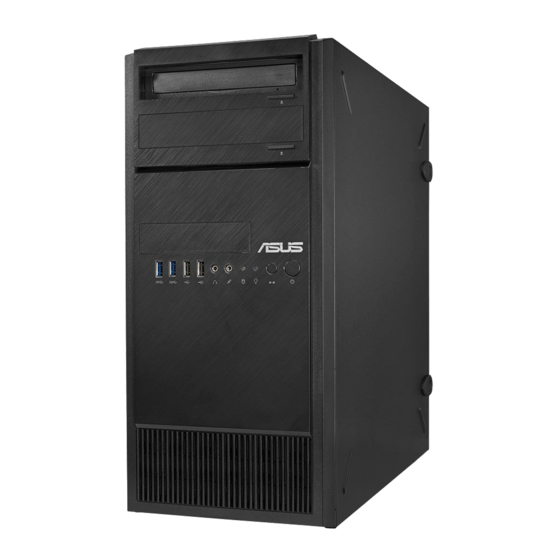
Front panel features The TS100-E9-PI4 Pedestal server features a simple yet stylish front panel design. The power and reset buttons, LED indicators, optical drive, and USB ports are all conveniently located at the fron panel for easy access. Optical Drive (Optional) Empty 5.25-inch bay... -
Page 18: Rear Panel Features
Rear panel features The rear panel includes a slot for the motherboard rear I/O ports, expansion slots, a vent for the system fan, and the power supply module. 500W Bronze Single power supply Power connector PS/2 keyboard / mouse port USB 2.0 ports USB 3.0 ports Serial port... -
Page 19: Internal Features
Internal features The TS100-E9-PI4 Pedestal server sytem includes the basic components as shown: Power supply unit 120 mm x 120 mm system fan ASUS P10S-X Server Board Expansion card locks Optical drive (Optional) 1 x 5.25-inch drive bay Front I/O board (hidden) 3 x 3.5-inch Internal HDD bays... -
Page 20: Led Information
LED information 1.7.1 Front panel LEDs HDD Access LED Power LED Icon Display status Description Power LED System power ON No activity HDD Access LED Read/write data into the HDD Blinking 1.7.2 Rear panel LEDs ACT/LINK LED SPEED LED ACT/LINK LED SPEED LED ACT/LINK LED SPEED LED... -
Page 21: Chapter 2: Hardware Information
Chapter 2: Hardware Information Hardware Information This chapter lists the hardware setup procedures that you have to perform when installing system components. It includes description of the jumpers and connectors on the motherboard. ASUS TS100-E9-PI4... -
Page 22: Chassis Cover
Chassis cover 2.1.1 Removing the side cover • Ensure that you unplug the power cord before removing the side cover. • Take extra care when removing the side cover. Keep your fingers from components inside the chassis that can cause injury, such as the CPU fan, rear fan, and other sharp-edged parts. • The images of the barebone server shown in this section are for reference purposes only and may not exactly match the model you purchase. To remove the side cover: Remove the two screws that secure the side cover. - Page 23 Slightly pull the side cover toward the rear just enough to detach it from the chassis. Remove the cover and set it aside. ASUS TS100-E9-PI4...
-
Page 24: Central Processing Unit (Cpu)
Intel Xeon E3-1200 v5 processor. ® ® • Upon purchase of the motherboard, ensure that the PnP cap is on the socket and the socket contacts are not bent. Contact your retailer immediately if the PnP cap is missing, or if you see any damage to the PnP cap/socket contacts/motherboard components. ASUS will shoulder the cost of repair only if the damage is shipment/ transit-related. • Keep the cap after installing the motherboard. ASUS will process Return Merchandise Authorization (RMA) requests only if the motherboard comes with the cap on the LGA1151 socket. • The product warranty does not cover damage to the socket contacts resulting from incorrect CPU installation/removal, or misplacement/loss/incorrect removal of the PnP cap. - Page 25 Retention tab Lift the load lever until the load plate is completely lifted. Load plate Position the CPU above the socket, ensuring that the gold triangle mark is on the bottom-left corner of the socket, then fit the CPU notches to the socket's CPU notches alignment keys. The CPU fits in only one orientation. Gold DO NOT force the CPU into the triangle Alignment socket to prevent bending the pins on mark the socket and damaging the CPU. Alignment ASUS TS100-E9-PI4...
- Page 26 Close the load plate (A), ensuring that the front edge of the load plate slides Load lever under the retention lock (B) then push down the load lever (C). Retention lock Insert the load lever under the retention tab to remove the PnP cap from the CPU socket. Load lever Retention tab Apply some Thermal Interface Material to the exposed area of the CPU that the heatsink will be in contact with, ensuring that it is evenly spread in a thin layer. Some heatsinks come with pre- applied Thermal Interface Material. If so, skip this step.
-
Page 27: Installing The Cpu Heatsink And Fan Assembly
2.2.2 Installing the CPU heatsink and fan assembly To install the CPU heatsink and fan assembly ASUS TS100-E9-PI4... -
Page 28: Uninstalling The Cpu Heatsink And Fan
Connect the CPU fan cable to the connector on the motherboard labeled CPU_FAN1. DO NOT forget to connect the CPU fan connector! Hardware monitoring errors can occur if you fail to plug this connector. 2.2.3 Uninstalling the CPU heatsink and fan To uninstall the CPU heatsink and fan: Disconnect the CPU fan cable from the connector on the motherboard. -
Page 29: System Memory
Memory Configuration DIMM DIMM Slot Per Populated per DIMM Type Speed Rank per DIMM Channel Channel Unbuffered DDR4 2133 Single Rank, Dual Rank Unbuffered DDR4 2133 Single Rank, Dual Rank • Always install DIMMs with the same CAS latency. For optimum compatibility, it is recommended that you obtain memory modules from the same vendor. • Start installing the DIMMs in slots A2 and B2 (Blue). ASUS TS100-E9-PI4... -
Page 30: Installing A Dimm On A Single Clip Dimm Socket
2.3.3 Installing a DIMM on a single clip DIMM socket Unlock a DIMM socket by pressing the DIMM notch retaining clip outward. Align a DIMM on the socket such that the notch on the DIMM matches the DIMM slot key on the socket. DIMM slot key Unlocked retaining clip A DIMM is keyed with a notch so that it fits in only one direction. DO NOT force a DIMM into a socket in the wrong direction to avoid damaging the DIMM. Hold the DIMM by both of its ends then insert the DIMM vertically into the socket. Apply force to both ends of the DIMM simultaneously until the retaining clip snaps back into place and the DIMM cannot be pushed in any further to ensure proper sitting of the DIMM. Locked Retaining Clip Always insert the DIMM into the socket vertically to prevent DIMM notch damage. • To install two or more DIMMs, refer to the user guide bundled in the motherboard package. -
Page 31: Front Panel Cover
Removing the front panel cover To remove the front panel cover: Locate the front panel assembly lock then slide it outward to unlock the latches that secures the front panel cover to the chassis. assembly lock Remove the front panel assembly from the chassis and set it aside. front panel assembly ASUS TS100-E9-PI4 2-11... -
Page 32: Inch Drives
5.25-inch drives This system comes with three 5.25-inch drive bays located on the upper front section of the chassis. If your system came with an optical drive, the optical drive occupies the topmost bay (1). The lower bays (2 and 3) are available for additional 5.25-inch optical, zip, or floppy disk drives. Installing a 5.25-inch drive To install a 5.25-inch drive: Remove the front panel cover. - Page 33 Connect the SATA cable to the SATA connector of the drive. Connect a SATA power cable from the power supply to the power connector of the drive. Reinstall the front panel cover. SATA power cable SATA cable ASUS TS100-E9-PI4 2-13...
-
Page 34: Hard Disk Drives (Hdd)
Hard disk drives (HDD) The server system supports three (3) 3.5-inch Serial ATA hard disk drives via the hard disk drive bays and one 2.5-inch HDD/SSD drive at the bottom of the HDD cage. Installing 3.5-inch HDDs To install 3.5-inch Serial ATA hard disk drives: Remove the side cover of the chassis. Refer to the Removing the side cover section for more information. Prepare the 3.5-inch HDD and the bundled set of screws. - Page 35 Secure the 3.5-inch HDD to the HDD cage using the bundled set of screws. Swing the HDD cage inwards until it clicks back into place. Connect the SATA cable and SATA power cable to the 3.5-inch HDD. ASUS TS100-E9-PI4 2-15...
- Page 36 Installing 2.5-inch HDD/SSD To install a 2.5-inch HDD/SSD: Remove the side cover of the chassis. Refer to the Removing the side cover section for more information. Prepare the 2.5-inch HDD/SDD and the bundled set of screws. Lay the system on its side on a flat and stable surface. Locate the HDD cage lock, press it up (A), then swing the HDD cage outwards (B). Align and insert the 2.5-inch HDD/SSD into the drive bay as shown. Push it all the way until its screw holes align with the holes on the drive bay.
- Page 37 Secure the 2.5-inch HDD/SSD to the HDD cage using the bundled set of screws. Swing the HDD cage inwards until it clicks back into place. Connect a SATA cable and a SATA power cable to the 2.5-inch HDD/SSD. ASUS TS100-E9-PI4 2-17...
-
Page 38: Expansion Cards
Expansion cards The system has expansion slots on the rear panel that allows you to install expansion cards or additional components. Ensure to unplug the power cord before installing or removing expansion cards. Failure to do so may cause severe damage to the motherboard and other system components! Read the documentation of the expansion card and make the necessary hardware settings for the card before installing them. 2.7.1 Installing an expansion card To install an expansion card: Lay the system on its side on a flat, stable surface. Press the PCI-E latch (A), hold it by its edge then lift it towards the rear (B). edge of the PCI-E latch PCI-E latch Remove the screw (A) that secures the metal bracket to the chassis then... - Page 39 PCI-E slot Align and insert the expansion card into the PCI-E slot. Lift the PCI-E latch inwards until it clicks into place securing the expansion card to the chassis. PCI-E latch (Optional) Replace the screw of the metal bracket. ASUS TS100-E9-PI4 2-19...
-
Page 40: Configuring An Expansion Card
2.7.2 Configuring an expansion card After installing the expansion card, configure the it by adjusting the software settings. Turn on the system and change the necessary BIOS settings, if any. See Chapter 5 for information on BIOS setup. Assign an IRQ to the card. Refer to the following tables. Install the software drivers for the expansion card. Standard Interrupt assignments Priority Standard function System Timer Keyboard Controller... -
Page 41: System Fan
Remove the four system fan screws at the rear panel. Keep the screws for later use. Hold the system fan with one hand while removing the system fan screws. Remove the system fan. Follow the previous instructions in reverse order if you want to reinstall the system fan. ASUS TS100-E9-PI4 2-21... -
Page 42: Cable Connections
Cable connections • The bundled system cables are pre-connected before shipment. You do not need to disconnect these cables unless you will remove pre-installed components to install additional devices. • Refer to Chapter 3 for detailed information on the connectors. Standard cables connected to the motherboard 24-pin ATX power connector (from power supply to motherboard) 8-pin ATX 12V power connector (from power supply to motherboard) System fan connector (from system fan to motherboard) SATA conectors (system default; from motherboard to SATA devices) USB connectors (from motherboard to front I/O board) System panel connector (from motherboard to front I/O board) 2-22 Chapter 2: Hardware Information... -
Page 43: Chapter 3: Motherboard Information
Chapter 3: Motherboard Information Motherboard Information This chapter includes the motherboard layout and brief descriptions of the jumpers and internal connectors. -
Page 44: Motherboard Layout
Motherboard layout Chapter 3: Motherboard Information... - Page 45 LPT connector (26-1 pin LPT1) 3-11 11. ATX power connectors (24-pin EATXPWR1, 8-pin EATX12V1) 3-12 System panel connector (20-1 pin PANEL1) 3-13 Auxiliary panel connector (20-2 pin AUX_PANEL1) 3-14 Chassis intrusion connector (2-pin INTRUSION1) 3-15 System Management Bus (SMBUS) connector 3-15 (5-1 pin SMBUS1) ASUS TS100-E9-PI4...
-
Page 46: Jumpers
Jumpers Clear RTC RAM (3-pin CLRTC1) This jumper allows you to clear the Real Time Clock (RTC) RAM in CMOS. You can clear the CMOS memory of date, time, and system setup parameters by erasing the CMOS RTC RAM data. The onboard button cell battery powers the RAM data in CMOS, which include system setup information such as system passwords. To erase the RTC RAM: Turn OFF the computer and unplug the power cord. Move the jumper cap from pins 1–2 (default) to pins 2–3. Keep the cap on pins 2–3 for about 5–10 seconds, then move the cap back to pins 1–2. Plug the power cord and turn ON the computer. Hold down the <Del> key during the boot process and enter BIOS setup to re- enter data. Except when clearing the RTC RAM, never remove the cap on CLRTC jumper default position. Removing the cap will cause system boot failure! If the steps above do not help, remove the onboard battery and move the jumper again to clear the CMOS RTC RAM data. After the CMOS clearance, reinstall the battery. Chapter 3: Motherboard Information... -
Page 47: Vga Controller Setting (3-Pin Vga_Sw1)
VGA controller setting (3-pin VGA_SW1) This jumper allows you to enable or disable the onboard VGA controller. Set to pins 1–2 to activate the VGA feature. LAN controller setting (3-pin LAN_SW1, LAN_SW2) ® These jumpers allows you to enable or disable the onboard Intel I210 Gigabit LAN controllers. Set to pins 1-2 to activate the Gigabit LAN feature. ASUS TS100-E9-PI4... -
Page 48: Me Firmware Force Recovery Setting (3-Pin Me_Rcvr1)
ME firmware force recovery setting (3-pin ME_RCVR1) This jumper allows you to force Intel Management Engine (ME) boot from recovery mode when ME become corrupted. Chapter 3: Motherboard Information... -
Page 49: Internal Connectors
C232 chipset, these connectors are for the Serial ATA signal cables for Serial ATA hard disk drives that allows up to 6Gb/s of data transfer rate. If you installed Serial ATA hard disk drives, you can create a RAID 0, RAID 1, RAID 10, or RAID 5 configuration. The actual data transfer rate depends on the speed of Serial ATA hard disks installed. Hard disk activity LED connector (4-pin HDLED1) This LED connector is for the storage add-on card cable connected to the SATA or SAS add-on card. The read or write activities of any device connected to the SATA or SAS add-on card causes the front panel LED to light up. ASUS TS100-E9-PI4... -
Page 50: Usb 2.0 Connector (10-1 Pin Usb78)
USB 2.0 connector (10-1 pin USB78) These connectors are for USB 2.0 ports. Connect the USB module cables to these connectors. These USB connectors comply with USB 2.0 specification that supports up to 480 Mbps connection speed. USB 3.0 connector (20-1 pin USB3_34, A-Type USB3_5) These connectors allow you to connect a USB 3.0 module for additional USB 3.0 front or rear panel ports. With an installed USB 3.0 module, you can enjoy all the benefits of USB 3.0 including faster data transfer speeds of up to 5Gbps, faster charging time for USB-chargeable devices, optimized power efficiency, and backward compatibility with USB 2.0. -
Page 51: Cpu, Front, And Rear Fan Connectors (4-Pin Frnt_Fan1-4, Rear_Fan1, Cpu_Fan1)
DO NOT forget to connect the fan cables to the fan connectors. Insufficient air flow inside the system may damage the motherboard components. • These are not jumpers! DO NOT place jumper caps on the fan connectors! • All fans feature the ASUS Smart Fan technology. Serial General Purpose Input/Output connector (6-1 pin SGPIO1) The SGPIO 1 connector is used for the Intel Rapid Storage Technology Enterprise SGPIO interface that controls the LED pattern generation, device information, and general purpose data. ASUS TS100-E9-PI4... -
Page 52: Trusted Platform Module Connector (14-1 Pin Tpm)
Trusted Platform Module connector (14-1 pin TPM) This connector supports a Trusted Platform Module (TPM) system, which can securely store keys, digital certificates, passwords, and data. A TPM system also helps enhance network security, protects digital identities, and ensures platform integrity. VGA connector (16-1 pin VGA_HDR1) This connector supports the VGA High Dynamic-Range interface. Chapter 3: Motherboard Information 3-10... -
Page 53: Serial Port Connector (10-1 Pin Com2)
This connector is for the serial (COM) port. Connect the serial port module cable to the connector, then install the module to a slot opening at the back of the system chassis. LPT connector (26-1 pin LPT1) The LPT (Line Printing Terminal) connector supports devices such as a printer. LPT standardizes as IEEE 1284, which is the parallel port interface on IBM PC-compatible computers. ASUS TS100-E9-PI4 3-11... -
Page 54: Atx Power Connectors (24-Pin Eatxpwr1, 8-Pin Eatx12V1)
ATX power connectors (24-pin EATXPWR1, 8-pin EATX12V1) These connectors are for the ATX power supply plugs. The power supply plugs are designed to fit these connectors in only one orientation. Find the proper orientation and push down firmly until the connectors completely fit. • DO NOT forget to connect the 24-pin and the 8-pin power plugs; otherwise, the system will not boot up. • Use of a power supply unit (PSU) with a higher power output is recommended when configuring a system with more power-consuming devices. The system may become unstable or may not boot up if the power is inadequate. • This motherboard supports ATX2.0 PSU or later version. • Ensure that your PSU can provide at least the minimum power required by your system. Chapter 3: Motherboard Information 3-12... -
Page 55: System Panel Connector (20-1 Pin Panel1)
BIOS settings. Pressing the power switch for more than four seconds while the system is ON turns the system OFF. Reset button (2-pin RESET) This 2-pin connector is for the chassis-mounted reset button for system reboot without turning off the system power. ASUS TS100-E9-PI4 3-13... -
Page 56: Auxiliary Panel Connector (20-2 Pin Aux_Panel1)
Auxiliary panel connector (20-2 pin AUX_PANEL1) This connector is for additional front panel features including front panel SMB, locator LED and switch, chassis intrusion, and LAN LEDs. Front panel SMB (6-1 pin FPSMB) These connectors connect the front panel SMBus cable. LAN activity LED (2-pin LAN1LINK and 2-pin LAN2LINK) These connectors are for Gigabit LAN activity LEDs on the front panel. -
Page 57: Chassis Intrusion Connector (2-Pin Intrusion1)
Chassis intrusion connector (2-pin INTRUSION1) This connector is for a chassis-mounted intrusion detection sensor or switch. Connect one end of the chassis intrusion sensor or switch cable to this connector. The chassis intrusion sensor or switch sends a high-level signal to this connector when a chassis component is removed or replaced. The signal is then generated as a chassis intrusion event. By default, the pin labeled “Chassis Signal” and “Ground” are shorted with a jumper cap. Remove the jumper caps only when you intend to use the chassis intrusion detection feature. System Management Bus (SMBUS) connector (5-1 pin SMBUS1) This connector controls the system and power management-related tasks. This connector processes the messages to and from devices rather than tripping the individual control lines. ASUS TS100-E9-PI4 3-15... - Page 58 Chapter 3: Motherboard Information 3-16...
-
Page 59: Chapter 4: Bios Setup
Chapter 4: BIOS Setup BIOS Setup This chapter tells how to change the system settings through the BIOS Setup menus. Detailed descriptions of the BIOS parameters are also provided. -
Page 60: Managing And Updating Your Bios
BIOS in the future. Copy the original motherboard BIOS using the BUPDATER utility. 4.1.1 ASUS CrashFree BIOS 3 utility The ASUS CrashFree BIOS 3 is an auto recovery tool that allows you to restore the BIOS file when it fails or gets corrupted during the updating process. You can update a corrupted BIOS file using a USB flash drive that contains the updated BIOS file. -
Page 61: Asus Ezflash Utility
To update the BIOS using EzFlash Utility: Insert the USB flash disk that contains the latest BIOS file to the USB port. Enter the BIOS setup program. Go to the Tool menu to select ASUS EzFlash Utility and press <Enter> to enable it. ASUS Tek. EzFlash Utility... -
Page 62: Bupdater Utility
The BUPDATER utility allows you to update the BIOS file in DOS environment using a bootable USB flash disk drive with the updated BIOS file. Updating the BIOS file To update the BIOS file using the BUPDATER utility: Visit the ASUS website at www.asus.com and download the latest BIOS file for the motherboard. Save the BIOS file to a bootable USB flash disk drive. Download the BUPDATER utility (BUPDATER.exe) from the ASUS support website at support.asus.com to the bootable USB flash disk drive you created earlier. Boot the system in DOS mode, then at the prompt, type: BUPDATER /i[filename].CAP where [filename] is the latest or the original BIOS file on the bootable USB flash disk drive, then press <Enter>. A:\>BUPDATER /i[file name]CAP... - Page 63 The utility verifies the file, then starts updating the BIOS file. ASUS Tek. EzFlash Utility Current Platform New Platform Platform : P10S-X Platform : P10S-X Version : 0200 Version : 0206 Build date: 07/20/2015 Build date: 08/01/2015 Start Programming Flash. DO NOT SHUTDOWN THE SYSTEM!!! Write DO NOT shut down or reset the system while updating the BIOS to prevent system boot failure! The utility returns to the DOS prompt after the BIOS update process is completed.
-
Page 64: Bios Setup Program
Press <F5> and select Yes to load the BIOS default settings. • The BIOS setup screens shown in this section are for reference purposes only, and may not exactly match what you see on your screen. • Visit the ASUS website (www.asus.com) to download the latest BIOS file for this motherboard. Chapter 4: BIOS Setup... -
Page 65: Bios Menu Screen
Monitor For displaying the system temperature, power status, and changing the fan settings Tool For configuring options for special functions Save & Exit For selecting the save & exit options For changing the event log settings Event Logs To select an item on the menu bar, press the right or left arrow key on the keyboard until the desired item is highlighted. ASUS TS100-E9-PI4... -
Page 66: Menu Items
4.2.3 Menu items The highlighted item on the menu bar displays the specific items for that menu. For example, selecting Main shows the Main menu items. The other items (Advanced, Event Logs, Boot, Monitor, Security, Tool, Save & Exit, and Event Logs) on the menu bar have their respective menu items. 4.2.4 Submenu items A solid triangle before each item on any menu screen means that the item has a submenu. To display the submenu, select the item and press <Enter>. -
Page 67: Main Menu
4.3.1 System Date [Day xx/xx/xxxx] Allows you to set the system date. 4.3.2 System Time [xx:xx:xx] Allows you to set the system time. ASUS TS100-E9-PI4... -
Page 68: Advanced Menu
Advanced menu The Advanced menu items allow you to change the settings for the CPU and other system devices. Take caution when changing the settings of the Advanced menu items. Incorrect field values can cause the system to malfunction. OS Type [Windows UEFI mode] Allows you to configure your system as UEFI mode or Legacy mode. [Windows UEFI mode] Configure system as UEFI mode. [Other OS] Configure system as Legacy mode. Chapter 4: BIOS Setup 4-10... -
Page 69: Trusted Computing
Allows you to restrict support to selected device. Auto will support both devices. Configuration options: [TPM 1.2] [TPM 2.0] [Auto] 4.4.2 Chipset Configuration System Agent (SA) Configuration Allows you to set System Agent (SA) parameters. VT-d [Enabled] Allows you to enable virtualization technology function on memory control hub. Configuration options: [Enabled] [Disabled] ASUS TS100-E9-PI4 4-11... - Page 70 Above 4GB MMIO BIOS assignment [Disabled] Allows you to enable or disable above 4GB MemoryMappedIO BIOS assignment. When aperture size is set to 2048 MB, this is disabled automatically. Configuration options: [Enabled] [Disabled] DMI/OPI Configuration DMI Max Link Speed [Auto] Allows you to set the DMI speed. Configuration options: [Auto] [Gen1] [Gen2] [Gen3] DMI Vc1 Control [Disabled] Allows you to enable or disable DMI Vc1. Configuration options: [Enabled] [Disabled] DMI Vcm Control [Enabled] Allows you to enable or disable DMI Vcm.
- Page 71 Power Down Unused Lanes [Auto] Allows you to power down unused lanes. [Disabled] No power saving [Auto] B IOS will power down unused lanes based in the max possible link width ASPM [Auto] Allows you to configure the PCIE ASPM. Configuration options: [Disabled] [Auto] [ASPM L0s] [ASPM L1] [ASPM L0sL1] PEG0 Max Payload size [Auto] Allows you to set the PEG0 max payload size. Configuration options: [Auto] [128 TLP] [256 TLP] ASUS TS100-E9-PI4 4-13...
- Page 72 Program PCIe ASPM after OpRom [Disabled] Allows you to select when to program the PCIe ASPM. [Disabled] PCIe ASPM will be programmed before OpROM. [Enabled] PCIe ASPM will be programmed after OpROM. Memory Configuration Maximum Memory Frequency [Auto] Allows you to set the maximum memory frequency. Configuration options: [Auto] [1067] [1333] [1600] [1867] [2133] [2400] [2667] [2933] [3200] Max TOLUD [Dynamic] Allows you to set the maximum value of TOLUD. Dynamic assignment would adjust TOLUD automatically based on largest MMIO length of installed graphic controller.
-
Page 73: Pci Express Configuration
Allows you to set PCH-IO parameters. PCI Express Configuration PCI Express Clock Gating [Enabled] Allows you to enable or disable PCI Express Clock Gating for each root port. Configuration options: [Disabled] [Enabled] DMI Link ASPM Control [Enabled] Allows you to enable or disable the control of Active State Power Management on SA side of the DMI link. Configuration options: [Disabled] [Enabled] ASUS TS100-E9-PI4 4-15... -
Page 74: Usb Configuration
USB Configuration USB Precondition[Disabled] Allows you to precondition work on USB host controller and root ports for faster enumeration. Configuration options: [Enabled] [Disabled] xDCI Support [Disabled] Allows you to enable or disable xDCI (USB OTG Device). Configuration options: [Disabled] [Enabled] USB Port Disable Override [Disabled] Allows you to enable or disable the corresponding USB port from reporting a Device Connection to the controller Configuration options: [Disabled] [Select Per-Pin] HD Audio Configuration... - Page 75 Intel Server Platform Services Intel TXT Information ASUS TS100-E9-PI4 4-17...
- Page 76 PCI/PCIE Subsystem Settings PCI Latency Timer [32 PCI Bus Clocks] Allows you to set the value to be programmed into PCI Latency Timer Register. Configuration options: [32 PCI Bus Clocks] [64 PCI Bus Clocks] [96 PCI Bus Clocks] [128 PCI Bus Clocks] [160 PCI Bus Clocks] [192 PCI Bus Clocks] [224 PCI Bus Clocks] [248 PCI Bus Clocks] PERR# Generation [Disabled] Allows you to enable or disable PCI Device tp generation PERR#. Configuration options: [Disabled] [Enabled] SERR# Generation [Disabled] Allows you to enable or disable PCI Device tp generation SERR#.
-
Page 77: Platform Configuration
[Enabled] Enables the support for USB devices on legacy operating systems (OS). [Auto] Allows the system to detect the presence of USB devices at startup. If detected, the USB controller legacy mode is enabled. If no USB device is detected, the legacy USB support is disabled. XHCI Hand-off [Disabled] This item is set to [Disabled] by default for the EHCI (enhanced host controller interface) support by XHCI drivers in operating systems. [Disabled] Support XHCI by XHCI drivers for operating systems with XHCI support. [Enabled] Support XHCI by BIOS for operating systems without XHCI support. ASUS TS100-E9-PI4 4-19... - Page 78 USB Mass Storage Driver Support [Enabled] Allows you to enable or disable the USB Mass Storage driver support. Configuration options: [Disabled] [Enabled] Port 60/64 Emulation [Enabled] This allows you to enable the I/O port 60h/64h emulation support. This should be enabled for the complete USB keyboard legacy support for non-USB aware OSes. Configuration options: [Disabled] [Enabled] USB hardware delays and time-outs USB transfer time-out [20 sec]...
- Page 79 Allows you to select the Intel LAN ROM type. Configuration options: [Disabled] [PXE] [iSCSI] Intel LAN2 Enable [Enabled] Allows you to enable or disable the Intel LAN. Configuration options: [Disabled] [Enabled] Intel LAN ROM Type [Disabled] Allows you to select the Intel LAN ROM type. Configuration options: [Disabled] [PXE] [iSCSI] Super IO Configuration ASUS TS100-E9-PI4 4-21...
-
Page 80: Serial Port 1 Configuration
Serial Port 1 Configuration Allows you to set the parameters of Serial Port 1. Serial Port [Enabled] Allows you to enable or disable Serial Port. Configuration options: [Disabled] [Enabled] Change Settings [Auto] Allows you to choose the setting for Super IO device. Configuration options: [Auto] [IO=3F8h; IRQ=4;] [IO=3F8h; IRQ=3, 4, 5, 6, 7, 9, 10, 11, 12;] [IO=2F8h; IRQ=3, 4, 5, 6, 7, 9, 10, 11, 12;] [IO=3E8h; IRQ=3, 4, 5, 6, 7, 9, 10, 11, 12;] [IO=2E8h; IRQ=3, 4, 5, 6, 7, 9, 10, 11, 12;] Serial Port 2 Configuration... -
Page 81: Serial Port Console Redirection
(which the user is using) will exchange data. Both computers should have the same or compatible settings. Terminal Type [VT-UTF8] Allows you to set the terminal type. [VT100] ASCII char set. [VT100+] Extends VT100 to support color, function keys, et. [VT-UTF8] Uses UTF8 encoding to map Unicode chars onto 1 or more bytes [ANSI] Extended ASCII char set ASUS TS100-E9-PI4 4-23... - Page 82 Bits per second [57600] Selects serial port transmission speed. The speed must be matched on the other side. Long or noisy lines may require lower speeds. Configuration options: [9600] [19200] [38400] [57600] [115200] Data Bits [8] Configuration options: [7] [8] Parity [None] A parity bit can be sent with the data bits to detect some transmission errors. [Mark] and [Space] parity do not allow for error detection. [None] None [Even] parity bit is 0 if the num of 1’s in the data bits is even [Odd] parity bit is 0 if num of 1’s in the data bits is odd [Mark] parity bit is always 1...
- Page 83 Out-of-Band Mgmt Port [COM1] Microsoft Windows Emergency Management Services (EMS) allows for remote management of a Windows Server OS through a serial port. Configuration options: [COM1] [COM2] Terminal Type [VT-UTF8] Allows you to set the terminal type for out-of-band management. Configuration options: [VT100] [VT100+] [VT-UTF8] [ANSI] Bits per second [115200] Allows you to set the serial port transmission speed. Configuration options: [9600] [19200] [57600] [115200] Flow Control [None] Allows you to set the flow control to prevent data loss from buffer overflow. Configuration options: [None] [Hardware RTS/CTS] [Software Xon/Xoff] ASUS TS100-E9-PI4 4-25...
-
Page 84: Acpi Settings
ACPI Settings Enable Hibernation [Enabled] Allows you to enable or disable the ability of the system to hibernate (OS/S4 Sleep State). Configuration options: [Disabled] [Enabled] This option may be not be effective with some OS. ACPI Sleep State [S3 (Suspend to RAM)] Allows you to select the highest ACPI sleep state the system will enter when the SUSPEND button is pressed. - Page 85 This item functions only if there is a serial port (COM1) connector on the motherboard Power On By RTC [Disabled] [Disabled] Disables RTC to generate a wake event. [Enabled] W hen set to [Enabled], the items RTC Alarm Date (Days) and Hour/Minute/ Second will become user-configurable with set values. SMART Settings SMART Self Test [Enabled] Allows you to run SMART Self Test on all HDDs during POST. Configuration options: [Disabled] [Enabled] ASUS TS100-E9-PI4 4-27...
-
Page 86: Cpu Configuration
WHEA Configurations WHEA Support [Enabled] This item allows you to enable or disable the WHEA support. Configuration options: [Disabled] [Enabled] 4.4.4 CPU Configuration The items in this menu show the CPU-related information that the BIOS automatically detects. Some items may not appear if your CPU does not support the related functions. Navigate to the second page of the screen to see the rest of items in this menu by pressing the Up or Down arrow keys. - Page 87 When set to [Enabled], a VMM can utilize the additional hardware capabilities provided by Vanderpool Technology. Configuration options: [Disabled] [Enabled] Hardware Prefetcher [Enabled] Allows you to enable or disable the MLC streamer prefetcher. Configuration options: [Disabled] [Enabled] Adjacent Cache Line Prefetch [Enabled] This item allows you to enable or disable prefetching of adjacent cache lines. Configuration options: [Disabled] [Enabled] ASUS TS100-E9-PI4 4-29...
- Page 88 CPU AES [Enabled] Allows you to enable or disable the CPU Advance Encryption Standard instructions. Configuration options: [Disabled] [Enabled] Boot performance mode [Turbo Performance] Allows you to select the CPU performance state during system boot before the operating system takes control. The CPU runs at a selected performance ratio based on CPU configuration. Configuration options: [Max Non-Turbo Performance] [Turbo Performance] HardWare P states (HWP) [Disabled] Allows you to enable or disable HWP support.
- Page 89 Configuration options: [Disabled] [Enabled] Package C state undemotion [Disabled] Allows you to enable or disable the Package C state undemotion. Configuration options: [Disabled] [Enabled] CState Pre-Wake [Enabled] Allows you to enable or disable the CState Pre-Wake. Selecting [Disabled] will set bit 30 of POWER_CTL MSR(0x1FC) to 1 to disable the CState Pre-Wake. Configuration options: [Disabled] [Enabled] Package C State limit [AUTO] Allows you set the Package C State limit. Configuration options: [C0/C1] [C2] [C3] C6] [C7] [C7s] [C8] [AUTO] CFG lock [Enabled] Allows you to configure MSR 0xE2[15], CFG lock bit. Configuration options: [Disabled] [Enabled] Intel TXT(LT) Support [Disabled] Allows you to enable or disable the Intel(R) TXT(LT) support. Configuration options: [Disabled] [Enabled] ASUS TS100-E9-PI4 4-31...
-
Page 90: Sata Configuration
4.4.5 SATA Configuration SATA Controller(s) [Enabled] Allows you to enable or disable the SATA Device. Configuration options: [Enabled] [Disabled] SATA Mode Selection [AHCI] This item allows you to set the SATA configuration. [AHCI] S et to [AHCI] when you want the SATA hard disk drives to use the AHCI (Advanced Host Controller Interface). The AHCI allows the onboard storage driver to enable advanced Serial ATA features that increases storage performance on random workloads by allowing the drive to internally optimize the order of commands. - Page 91 HDD Unlock [Enabled] Selecting [Enabled] will indicate that the HDD password unlock in the OS is enabled. Configuration options: [Disabled] [Enabled] LED Locate [Enabled] Selecting [Enabled] will indicate that the LED/SGPIO hardware is attached and ping to locate feature is enabled on the OS. Configuration options: [Disabled] [Enabled] IRRT Only on eSATA [Enabled] [Disabled] Any RAID volume can span internal and eSATA drives. [Enabled] Only IRRT volumes can span internal and eSATA drives. ASUS TS100-E9-PI4 4-33...
-
Page 92: Network Stack Configuration
Smart Response Technology [Enabled] Allows you to enable or disable the Smart Response Technology. Configuration options: [Disabled] [Enabled] OROM UI Normal Delay [4 sec] Allows you to select the delay time of the OROM UI Splash Screen in a normal status. Configuration options: [2 sec] [4 sec] [6 sec] [8 sec] RST Force Form [Disabled] Allows you to enable or disable Form for Intel Rapid Storage Technology. -
Page 93: Csm Configuration
The values range from 0 to 5. Media detect count [1] Set the number of times presence of media will be checked. Use the <+> or <-> to adjust the value. The values range from 1 to 50. 4.4.7 CSM Configuration CSM Support [Enabled] This option allows you to enable or disable CSM Support. Configuration options: [Disabled] [Enabled] ASUS TS100-E9-PI4 4-35... -
Page 94: Nvme Controller And Drive Information
GateA20 Active [Upon Request] This allows you to set the GA20 option. [Upon Request] GA20 can be disabled using BIOS services. [Always] D o not allow disabling GA20; this option is useful when any RT code is executed above 1MB Option ROM Messages [Force BIOS] This allows you to set the display mode for option ROM. Configuration options: [Force BIOS] [Keep Current] Boot Option filter [Legacy only] This option allows you to control the Legacy/UEFI ROMs priority. -
Page 95: Security Menu
Select the Administrator Password item and press <Enter>. From the Create New Password box, key in a password, then press <Enter>. Confirm the password when prompted. To change an administrator password: Select the Administrator Password item and press <Enter>. From the Enter Current Password box, key in the current password, then press <Enter>. From the Create New Password box, key in a new password, then press <Enter>. Confirm the password when prompted. To clear the administrator password, follow the same steps as in changing an administrator password, but press <Enter> when prompted to create/confirm the password. ASUS TS100-E9-PI4 4-37... -
Page 96: User Password
User Password To set a user password: Select the User Password item and press <Enter>. From the Create New Password box, key in a password, then press <Enter>. Confirm the password when prompted. To change a user password: Select the User Password item and press <Enter>. From the Enter Current Password box, key in the current password, then press <Enter>. From the Create New Password box, key in a new password, then press <Enter>. Confirm the password when prompted. Secure Boot Menu This item allows you to customize the Secure Boot settings. Secure Boot Control [Disabled] This item allows you to enable or disable the Secure Boot flow control. -
Page 97: Boot Menu
Platform Key (PK) Configuration options: [Set New Key] [Delete] Key Exchange Keys / Authorized Signatures / Forbidden Signatures / Authorized TimeStamps Configuration options: [Set New Key] [Delete] [Append] Boot Menu The Boot menu items allow you to change the system boot options. Bootup NumLock State [On] Allows you to select the power-on state for the NumLock. Configuration options: [Off] [On] ASUS TS100-E9-PI4 4-39... -
Page 98: Network Device Bbs Priorities
These items specify the boot device priority sequence from the available devices. The number of device items that appears on the screen depends on the number of devices installed in the system. • To select the boot device during system startup, press <F8> when ASUS Logo appears. • To access Windows OS in Safe Mode, please press <F8> after POST. Set the booting order of network devices. -
Page 99: Monitor Menu
Configuration options: [Generic Mode] [High Speed Mode] [Full Speed Mode] Tool menu The Tool menu items allow you to configure options for special functions. Select an item then press <Enter> to display the submenu. ASUS EZ Flash Allows you to run ASUS EZ Flash BIOS ROM Utility when you press <Enter>. Refer to the ASUS EZ Flash Utility section for details. ASUS TS100-E9-PI4 4-41... -
Page 100: Save & Exit Menu
Save & Exit menu The Exit menu items allow you to save or discard your changes to the BIOS items. Pressing <Esc> does not immediately exit this menu. Select one of the options from this menu or <F10> from the legend bar to exit. Discard Changes and Exit Exit System setup without saving any changes. -
Page 101: Event Logs Menu
Change this to enable or disable all features of Smbios Event Logging during boot. Configuration options: [Disabled] [Enabled] Erasing Settings Erase Event Log [No] Choose options for erasing Smbios Event Log. Erasing is done prior to any logging activation during reset. Configuration options: [No] [Yes, Next reset] [Yes, Every reset] ASUS TS100-E9-PI4 4-43... -
Page 102: Custom Options
When Log is Full [Do Nothing] Allows you to choose options for reactions to a full Smbios Event Log. Configuration options: [Do Nothing] [Erase Immediately] Smbios Event Log Standard Settings Log System Boot Event [Disabled] Allows you to enable or disable logging of System boot event. Configuration options: [Enabled] [Disabled] MECI [1] Also known as Multiple Event Count Increment, and allows you to set the value for the... -
Page 103: Chapter 5: Raid Configuration
Chapter 5: RAID Configuration RAID Configuration This chapter provides instructions for setting up, creating, and configuring RAID sets using the available utilities. -
Page 104: Setting Up Raid
Setting up RAID ® ® The motherboard comes with the Intel C232 controller that supports Intel Rapid Storage Technology enterprise Option ROM Utility with RAID 0, RAID 1, RAID 10, and RAID 5 ® support (for Windows OS only). 5.1.1 RAID definitions RAID 0 (Data striping) optimizes two identical hard disk drives to read and write data in parallel, interleaved stacks. -
Page 105: Installing Hard Disk Drives
RAID controller. For example, use the Intel Rapid Storage Technology ® enterprise SATA Option ROM Utility if you installed Serial ATA hard disk drives on the Serial ATA connectors supported by the Intel C232 chipset. ® ASUS TS100-E9-PI4... -
Page 106: Intel
® Intel Rapid Storage Technology enterprise SATA Option ROM Utility The Intel Rapid Storage Technology enterprise SATA Option ROM utility allows you to ® create RAID 0, RAID 1, RAID 10 (RAID 1+0), and RAID 5 set from Serial ATA hard disk drives that are connected to the Serial ATA connectors supported by the Southbridge. -
Page 107: Creating A Raid Set
]-Prev/Next [TAB]-(M)aster [SPACE]-(R)ecovery [ENTER]-Done Use the up/down arrow keys to move the selection bar then press <Space> to select a disk. A small triangle before the Port number marks the selected drive. Press <Enter> when you are done. ASUS TS100-E9-PI4... - Page 108 Use the up/down arrow keys to select the stripe size for the RAID array (for RAID 0, 10 and 5 only) then press <Enter>. The available stripe size values range from 4 KB to 128 KB. The following are typical values: RAID 0: 128KB RAID 10:...
-
Page 109: Deleting A Raid Set
<N> to return to the DELETE VOLUME menu. DELETE VOLUME VERIFICATION ALL DATA IN THE VOLUME WILL BE LOST! (This does not apply to Recovery volumes) Are you sure you want to delete volume “Volume0”? (Y/N): ASUS TS100-E9-PI4... -
Page 110: Resetting Disks To Non-Raid
5.2.3 Resetting disks to Non-RAID Take caution before you reset a RAID volume hard disk drive to non-RAID. Resetting a RAID volume hard disk drive deletes all internal RAID structure on the drive. To reset a RAID set: From the utility main menu, select 3. Reset Disks to Non-RAID and press <Enter>. Press the up/down arrow keys to select the drive(s) or disks of the RAID set you want to reset, then press <Space>. -
Page 111: Exiting The Intel ® Rapid Storage Technology Enterprise Sata Option Rom Utility
Rebuild completes in the operating system. Select the port of destination disk for rebuilding (ESC to exit): Port Drive Model Serial # Size XXXXXXXXXXX XXXXXXXX XXX.GB ]-Previous/Next [ENTER]-Select [ESC]-Exit Select a destination disk with the same size as the original hard disk. ASUS TS100-E9-PI4... - Page 112 The utility immediately starts rebuilding after the disk is selected. When done, the status of the degraded RAID volume is changed to “Rebuild”. Intel(R) Rapid Storage Technology enterprise - SATA Option ROM - 3.6.0.1023 Copyright(C) 2003-12 Intel Corporation. All Rights Reserved. MAIN MENU 1.
-
Page 113: Setting The Boot Array In The Bios Setup Utility
Use up/down arrow keys to select the boot priority and press <Enter>. See the Boot menu section of Chapter 4 for more details. From the Exit menu, select Save Changes & Exit, then press <Enter>. When the confirmation window appears, select Yes, then press <Enter>. ASUS TS100-E9-PI4 5-11... -
Page 114: Intel ® Rapid Storage Technology Enterprise (Windows)
Intel Rapid Storage Technology enterprise ® (Windows) The Intel Rapid Storage Technology enterprise allows you to create RAID 0, RAID 1, RAID ® 10 (RAID 1+0), and RAID 5 set(s) from Serial ATA hard disk drives that are connected to the Serial ATA connectors. -
Page 115: Creating A Raid Set
Select the Volume Size tab then drag the bar to set the volume size. Click Next. • If you do not want to keep the data on one of the selected disks, select NO when prompted. • If you want to Enable volume write-back cache or Initialize volume, click Advanced. ASUS TS100-E9-PI4 5-13... - Page 116 Confirm the volume creation, then click Create Volume to continue. This process could take a while depending on the number and size of the disks. You can continue using other applications during this time. Wait until the process is completed, then click OK when prompted. You still need to partition your new volume using Windows Disk Management before adding any data.
-
Page 117: Changing A Volume Type
OK. The available stripe size values range from 4 KB to 128 KB. The following are typical values: RAID 0: 128KB RAID 10: 64KB RAID 5: 64KB We recommend a lower stripe size for server systems, and a higher stripe size for multimedia computer systems used mainly for audio and video editing. ASUS TS100-E9-PI4 5-15... -
Page 118: Deleting A Volume
5.3.3 Deleting a volume Be cautious when deleting a volume. You will lose all data on the hard disk drives. Before you proceed, ensure that you back up all your important data from your hard drives. To delete a volume: From the Volumes field in the utility main menu, select the volume that you want to delete. -
Page 119: Preferences
Allow you to set to show the notification area icon and show system information, warning, or errors here. E-Mail Preferences Allow you to set to sent e-mail of the following events: • Storage system information • Storage system warnings • Storage system errors ASUS TS100-E9-PI4 5-17... - Page 120 Chapter 5: RAID Configuration 5-18...
-
Page 121: Chapter 6: Driver Installation
Chapter 6: Driver Installation Driver Installation This chapter provides the instructions for installing the necessary drivers for different system components. -
Page 122: Raid Driver Installation
RAID driver installation After creating the RAID sets for your server system, you are now ready to install an operating system to the independent hard disk drive or bootable array. This part provides the instructions on how to install the RAID controller drivers during OS installation. 6.1.1 Creating a USB flash drive with RAID driver When installing Windows... - Page 123 Click Browse to continue. Locate the driver in the corresponding folder of the Support DVD or USB flash drive and then click OK to continue. Select the RAID controller driver you need from the list and click Next. ASUS TS100-E9-PI4...
- Page 124 When the system finishes loading the RAID driver, Replace the motherboard Support DVD with the Windows Server installation disc. • Remove the USB flash drive. • Select the drive to install Windows and click Next. Follow succeeding screen instructions to continue. Chapter 6: Driver Installation...
-
Page 125: Management Applications And Utilities Installation
• The contents of the support DVD are subject to change at any time without notice. Visit the ASUS website (www.asus.com) for the latest updates on software and utilities. •... -
Page 126: Drivers Menu Tab
6.3.1 Drivers menu tab The Drivers Menu shows the available device drivers if the system detects installed devices. Install the necessary drivers to activate the devices. 6.3.2 Utilities menu tab The Utilities menu displays the software applications and utilities that the motherboard supports. -
Page 127: Manual Menu
You need an internet browser installed in your OS to view the User Guide. 6.3.4 Contact information menu The Contact menu displays the ASUS contact information, e-mail addresses, and useful links if you need more information or technical support for your motherboard. ASUS TS100-E9-PI4... -
Page 128: Installing The Intel ® Chipset Device Software Driver
® 6.3.5 Installing the Intel Chipset device Software driver This section provides the instructions on how to install the Intel chipset device software on ® the system. You need to manually install the Intel chipset device software on a Windows Operating System. - Page 129 Select Yes to accept the terms of the License Agreement and continue the process. Read the Readme File Information and press Next to continue the installation. Toggle Yes, I want to restart the computer now and click Finish to complete the setup process. ASUS TS100-E9-PI4...
-
Page 130: Installing The Intel ® I210 Gigabit Adapters Driver
® Installing the Intel I210 Gigabit Adapters driver This section provides the instructions on how to install the Intel I210 Gigabit Adapter ® Driver on the system. To install the Intel I210 Gigabit Adapters Driver on the Windows operating system: ®... - Page 131 Tick I accept the terms in the license agreement and click Next to continue. From the Setup Options window, click Next to start the installation. By default, Intel(R) PROSet for Windows Device Manager and Windows PowerShell Module are ticked. ASUS TS100-E9-PI4 6-11...
- Page 132 Click Install to start the installation. When the installation is done, press Finish to complete the installation. 6-12 Chapter 6: Driver Installation...
-
Page 133: Installing The Vga Driver
ASSETUP.EXE from the BIN folder. Double-click the ASSETUP.EXE to run the support DVD. From the Main Menu, click ASPEED AST1400/AST2400 Display Driver on the Drivers tab to start the installation. From the installation window, click Next to start the installation. ASUS TS100-E9-PI4 6-13... - Page 134 Click Install to proceed with the installation. Click Finish to complete the installation. 6-14 Chapter 6: Driver Installation...
-
Page 135: Appendix
Appendix Appendix This appendix includes additional information that you may refer to when configuring the motherboard. -
Page 136: P10S-X Block Diagram
P10S-X block diagram Appendix... -
Page 137: Asus Contact Information
ASUS contact information ASUSTeK COMPUTER INC. Address 4F, No. 150, Li-Te Rd., Peitou, Taipei 112, Taiwan Telephone +886-2-2894-3447 +886-2-2890-7798 Web site http://www.asus.com Technical Support Telephone +86-21-38429911 +86-21-58668722 ext: 9101 Online Support http://support.asus.com/techserv/techserv.aspx ASUSTeK COMPUTER INC. (Taiwan) Address 4F, No. 150, Li-Te Rd., Peitou, Taipei 112, Taiwan... - Page 138 800 Corporate Way, Fremont, CA 94539, USA +1-510-608-4555 Web site http://usa.asus.com Technical Support Support fax +1-812-284-0883 General support +1-812-282-2787 Online support http://support.asus.com/techserv/techserv.aspx ASUS COMPUTER GmbH (Germany and Austria) Address Harkort Str. 21-23, D-40880 Ratingen, Germany +49-2102-959911 Web site http://www.asus.de Online contact http://www.asus.de/sales Technical Support Telephone +49-1805-010923...
- Page 139 Web site http://www.asus.com Technical Support Telephone +31-(0)591-5-70292 +31-(0)591-666853 E-mail advance.rma.eu@asus.com Online Support http://support.asus.com/techserv/techserv.aspx ASUS Polska Sp. z o.o. (Poland) Address Ul. Postępu 6, 02-676 Warszawa, Poland Web site http://pl.asus.com Technical Support Telephone +48-225718033 Online Support http://support.asus.com/techserv/techserv.aspx ASK-Service (Russia and CIS) Address г.Москва, ул.
- Page 140 Appendix...
Need help?
Do you have a question about the TS100-E9-PI4 and is the answer not in the manual?
Questions and answers