optris PI 200 Operator's Manual
Hide thumbs
Also See for PI 200:
- Operator's manual (86 pages) ,
- Operator's manual (45 pages) ,
- Operator's manual (85 pages)

Subscribe to Our Youtube Channel
Related Manuals for optris PI 200


Summary of Contents for optris PI 200
- Page 1 Operator’s Manual ® optris 160/ 200/ 230/ 400i/ 450i/ 450i G7/ 640/ 640 G7/ 05M/ 08M/ 1M Infrared camera...
- Page 2 Optris GmbH Ferdinand-Buisson-Str. 14 13127 Berlin Germany Tel.: +49 30 500 197-0 Fax: +49 30 500 197-10 E-mail: info@optris.global Internet: www.optris.global...
-
Page 3: Table Of Contents
Table of contents Table of contents Table of contents .............................. 3 General Notes ............................7 Intended use ............................7 Warranty ............................. 8 Scope of delivery ..........................9 Maintenance ............................9 1.4.1 Cleaning ............................9 Model overview ..........................10 Technical Data ............................11 General specifications ........................ - Page 4 Measurement specifications ......................16 Optical specifications ........................21 Mechanical Installation .......................... 31 Dimensions ............................31 Changing the lens ..........................39 Fixing the focus of the lens (only for PI 05M/ 08M/ 1M) ..............40 Mounting accessories (optional) ....................... 42 High temperature accessories ......................43 3.5.1 CoolingJacket ...........................
- Page 5 Table of contents Process interface ..........................52 4.1.1 PIN allocation ..........................54 4.1.2 Industrial Process Interface (optional) ..................56 Example for a Fail-Safe monitoring of the PI with a PLC ..............59 USB cable extension ........................61 IRmobile App ............................63 Software PIX Connect ..........................
- Page 6 Determination of unknown emissivity ....................81 Characteristic emissivity ........................83 Appendix A – Table of emissivity for metals ....................84 Appendix B – Table of emissivity for non-metals ..................86 Appendix C – Quick start for serial communication ................... 87 Appendix D –...
-
Page 7: General Notes
Thank you for choosing the optris PI infrared camera. The optris PI calculates the surface temperature based on the emitted infrared energy of objects [►7 Basics of Infrared Thermometry]. The two-dimensional detector (FPA - focal plane array) allows a measurement of an area and will be shown as thermal image using standardized palettes. The radiometric processing of the picture data enables the user to do a comfortable detailed analysis with the software PIX Connect. -
Page 8: Warranty
Avoid abrupt changes of the ambient temperature. Avoid static electricity, arc welders, and induction heaters. Keep away from very strong EMF (electromagnetic fields). In case of problems or questions which may arise when you use the infrared camera, please contact our service department. -
Page 9: Scope Of Delivery
General Notes 1.3 Scope of delivery PI 160, PI 200, PI 230, PI 400i, PI 450i, PI 450i G7, PI 640, PI 640 G7, PI 05M, PI 08M or PI 1M incl. 1 lens USB-cable: 1 m (standard scope of supply, no IP67 protection class) 1 m, 3 m, 5 m, 10 m, 20 m (optional, for industrial applications, with IP67) ... -
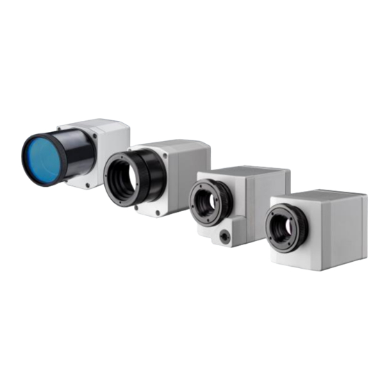
Page 10: Model Overview
-20 to 900 °C 7.5 - 13 µm 120 Hz Surface measurements in industrial application 200 to 1500 °C (optional) PI 200/ PI 230 BI-SPECTRAL -20 to 900 °C 7.5 - 13 µm 128 Hz Synchronous recording of VIS and IR videos and images 200 to 1500 °C (optional) -
Page 11: Technical Data
Dimensions: PI 160/ PI 200/ PI 230: 45 x 45 x 60 - 76 mm (depending on lens and focus position) PI 400i/ PI 450i (450i G7)/ PI 640 (640 G7): 46 x 56 x 76 - 100 mm (depending on lens and focus position) PI 640 microscope optics: 46 x 56 x 119 –... - Page 12 Vibration IEC 60068-2-6 (sinus shaped) IEC 60068-2-64 (broadband noise) Shock IEC 60068-2-27 (25 G and 50 G) Used standards for vibration and shock: Figure 1: Used standards Stress program (camera in operation): Shock, half sinus 25 G – testing Ea 25 G (acc. IEC 60068-2-27) Acceleration 245 m/s (25 G)
- Page 13 Technical Data Pulse duration 11 ms Number of directions (3 axes with 2 directions each) Duration 600 Shocks (100 Shocks each direction) Shock, half sinus 50 G – testing Ea 50 G (acc. IEC 60068-2-27) Acceleration 490 m/s (50 G) Pulse duration 11 ms Number of directions...
- Page 14 Duration 1:30 h (3 x 0.30 h) Vibration, broadband noise – testing Fh (acc. IEC60068-2-64) Frequency range 10 - 2000 Hz Acceleration 39.3 m/s (4.01 G Frequency spectrum 10 - 106 Hz 0.9610 (m/s (0.010 G /Hz) 106 - 150 Hz +6 dB/ Octave 150 - 500 Hz 1.9230 (m/s...
-
Page 15: Electrical Specifications
Technical Data 2.2 Electrical specifications Power Supply: 5 VDC (powered via USB 2.0 interface) Current draw: Max 500 mA AO: Output Standard Process Interface recording status, line scan status, 0 - 10 V (Main measure area, measure area, internal temperature, flag status, (PIF out) alarm, frame sync, fail-safe, external communication) [►Appendix F –... -
Page 16: Measurement Specifications
Software PIX Connect For an ideal combination of IR and VIS image we recommend the 41° lens for PI 200 and the 23° lens for PI 230 Accuracy statement effective from 150 °C The following options can be set: Option 1 (IR with 96 Hz at 160 x 120 px; VIS with 32 Hz at 640 x 480 px);... - Page 17 Technical Data PI 400i PI 450i PI 450i G7 Temperature ranges -20...100 °C; 0...250 °C; (20) 150...900 °C ; Option: 200…1500 °C 200…1500 °C 150…900 °C Sighting range 0…250 °C Spectral range 7.5 - 13 µm 7.9 µm Detector UFPA, 382 x 288 pixel @ 80 Hz (switchable to 27 Hz) Lenses (FOV) 18°...
- Page 18 PI 640 PI 640 G7 Temperature ranges -20...100 °C; 0...250 °C; (20) 150...900 °C 200…1500 °C Option: 200…1500 °C 150…900 °C Sighting range 0…250 °C Spectral range 7.5 - 13 µm 7,9 µm Detector UFPA, 640 x 480 Pixel @ 32 Hz 640 x 120 Pixel @ 125Hz Lenses (FOV) 15°...
- Page 19 Technical Data PI 05M PI 08M PI 1M Temperature ranges 900 … 2450 °C (27 Hz mode) 575 …1900 °C (27 Hz mode) …1800 °C (27 Hz mode) …1800 °C (80 Hz and 32 Hz mode) 950 … 2450 °C (80 Hz and 32 Hz mode) 625 …...
- Page 20 Emissivity 0.100...1.100 Software PIX Connect +75 °C start temperature for optics with focal length f= 50 mm, f= 75 mm An additionally purchased lens for the PI 05M/ 08M/ 1M camera comes with the corresponding protective tube At an ambient temperature of 25 ° C Specified NETD value applies to all frequencies...
-
Page 21: Optical Specifications
"near" and the turning in of the lens to the focus setting "infinity". The visual camera (PI 200/230 only) is adjusted with the supplied focusing tool (Figure 4). For this purpose, the focusing tool with the two pins is placed on the visual camera and is focused to "near"... - Page 22 They display the connection between the distance of the measured object and the size of the pixel (Table 2). With the help of BI-SPECTRAL technology at PI 200/ 230, a visual image (VIS) can be combined with a thermal image (IR). Both can be finally captured time synchronously.
- Page 23 Technical Data ® Figure 6: Measurement field of the infrared camera optris PI representing the 23° x 17° lens...
- Page 24 Wide angle lenses have a radial distortion due to their large opening angle; the software PIX Connect has an algorithm which corrects this distortion. As an alternative to the tables below, the optics calculator can also be used on the optris website (https://www.optris.global/optics-calculator) or via the optris calculator app. The...
- Page 25 Technical Data Table 2: * Note: The accuracy of measurement can be outside of the specifications for distances below the defined minimum distance.
- Page 26 * Note: The accuracy of measurement can be outside of the specifications for distances below the defined minimum distance.
- Page 27 Technical Data * Note: The accuracy of measurement can be outside of the specifications for distances below the defined minimum distance.
- Page 28 * Note: The accuracy of measurement can be outside of the specifications for distances below the defined minimum distance.
- Page 29 Technical Data * Note: The accuracy of measurement can be outside of the specifications for distances below the defined minimum distance. PI 05M and PI 08M is only available with OF25 optics...
- Page 30 * Note: The accuracy of measurement can be outside of the specifications for distances below the defined minimum distance. PI 05M and PI 08M is only available with OF25 optics...
-
Page 31: Mechanical Installation
Mechanical Installation 3 Mechanical Installation 3.1 Dimensions The PI is equipped with two metric M4 thread holes on the bottom side (6 mm depth) and can be installed either directly via these threads or with help of the tripod mount (also on bottom side). The tightening torque of the M4 screws for mounting the PI camera should be between 1 ... - Page 32 Figure 7: PI 160/ PI 400i/ PI 450i/ PI 450i G7, dimensions [mm]...
- Page 33 Mechanical Installation Figure 8: PI 200/ PI 230, dimensions [mm]...
- Page 34 Figure 9: PI 640/ PI 640 G7, optics 29°/33° & 53°/60°, dimensions [mm]...
- Page 35 Mechanical Installation Figure 10: PI 640/ PI 640 G7, optics 13°/15°, dimensions [mm]...
- Page 36 Figure 11: PI 640/ PI 640 G7, optics 80°/90°, dimensions [mm]...
- Page 37 Mechanical Installation Figure 12: PI 640, microscope optics 10°/12°, dimensions [mm]...
- Page 38 Figure 13: PI 05M/ PI 08M/ PI 1M, dimensions [mm]...
-
Page 39: Changing The Lens
Mechanical Installation 3.2 Changing the lens The PI camera is offered with several different lenses (lenses depending on the camera variant). To change a lens, rotate it as shown below. For the PI 05M, PI 08M and PI 1M, the protective tube must first be turned off (see Figure 5). -
Page 40: Fixing The Focus Of The Lens (Only For Pi 05M/ 08M/ 1M)
3.3 Fixing the focus of the lens (only for PI 05M/ 08M/ 1M) With the PI 05M, PI 08M and PI 1M, it is possible to fix the focus of the lens. To do this, unscrew the protective tube of the camera (see Figure 5). There are three small holes on the lens. Take the three screws that are included and attach them to the three holes. - Page 41 Mechanical Installation Figure 19: Focusing screws for focus ring...
-
Page 42: Mounting Accessories (Optional)
3.4 Mounting accessories (optional) Figure 20: Mounting base, stainless steel, adjustable in 2 axes [Part No.: ACPIMB] Figure 21: Protective housing, stainless steel, Incl. Mounting base [Part No.: ACPIPH]... -
Page 43: High Temperature Accessories
Mechanical Installation 3.5 High temperature accessories 3.5.1 CoolingJacket The IR camera can be used at ambient temperature up to 50 °C (up to 70 °C with PI 450i/ PI 450i G7). For higher temperatures (up to 180 °C) the CoolingJacket is provided. ... - Page 44 Figure 22: CoolingJacket – Dimensions...
-
Page 45: Coolingjacket Advanced
Mechanical Installation Figure 24: CoolingJacket with mounting bracket Figure 23: CoolingJacket for PI [Part No.: ACPIxxxCJ] 3.5.2 CoolingJacket Advanced The CoolingJacket Advanced is available as Standard Version and Extended Version. The IR camera can be used at ambient temperature up to 50 °C (up to 70 °C with PI 450i/ PI 450i G7). - Page 46 Standard Version Figure 25: CoolingJacket Advanced [Part No.: ACPIxxxCJAS], Standard Version - Dimensions...
- Page 47 Mechanical Installation Extended Version The Extended Version is provided for applications of the PI series with the PI Netbox and industrial PIF or the USB Server Gigabit and industrial PIF. Both PI Netbox and industrial PIF or USB Server Gigabit and industrial PIF can be integrated in the CoolingJacket. Figure 26: Cooling Jacket Advanced (Extended Figure 27:Cooling Jacket Advanced (Extended Version) Version) with PI Netbox and industrial PIF...
- Page 48 Figure 28: CoolingJacket Advanced [Part No.: ACPIxxxCJAE], Extended Version – Dimensions...
-
Page 49: Laminar Air Purge For Coolingjacket
Mechanical Installation 3.5.3 Laminar air purge for CoolingJacket Laminar air purge for front mounting of the CoolingJacket Advanced (Standard and Extended). Two different versions are available: One for standard camera applications [Part-No.: ACCJAAPLS] and the other for line scanning applications [Part-No.: ACCJAAPLL]. Those two versions are fitting to all focusing units with production date ≥01/2018. -
Page 50: Outdoor Protective Housing
3.5.4 Outdoor protective housing The infrared camera PI and the USB server can also be used for outdoor applications by using the outdoor protective housing. The outdoor protective housing can be used for any PI camera (lenses up to 90° FOV) ... -
Page 51: Electrical Installation
Electrical Installation 4 Electrical Installation At the back side of the PI there are the two connector plugs. The left plug is for the USB cable. The right connector plug is only used for the process interface. Figure 30: Backside of the camera with connectors Plug for USB cable Plug for PIF cable... -
Page 52: Process Interface
4.1 Process interface The process interface (electronics within cable as well as industrial interface) must be powered separately (5-24 VDC). Before switching on the power the PIF cable must be connected to the camera. The PI is equipped with a process interface (cable with integrated electronics and terminal block), which can be programmed via the software as an Analog Input (AI) and Digital Input (DI) in order to control the camera or as an Analog Output (AO) in order to control... - Page 53 Electrical Installation Figure 31: Configuration Standard Process Interface (PIF) The standard process interface provides the following inputs and outputs: Name Description max range / status Analog input 0-10 V Digital input 24 V (active-low = 0…0,6 V) Analog output 0-10 V Alarm output 0/ 10 V Depending on supply voltage;...
-
Page 54: Pin Allocation
4.1.1 PIN allocation 1 VCC 1 INT 2 GND 2 SDA (I²C) 3 SCL (I²C) 4 D - 4 DGND 5 D + 5 3.3 V (Out) Figure 32: Rear side of the camera... - Page 55 Electrical Installation If the process interface of the camera is directly connected to external hardware (without using the supplied PIF cable) an activation of the field „Support proprietary PIF cable” in the menu Tools/ Configuration/ Device (PIF) in the PIX Connect software is necessary. Figure 33: Support proprietary PIF cable Consider that the input of the PIF is not protected if there is a direct PIF connection! A voltage >...
-
Page 56: Industrial Process Interface (Optional)
4.1.2 Industrial Process Interface (optional) For use in industrial environment the industrial process interface with 500 V AC isolation voltage between PI and process is available (connection box with IP65, 5 m, 10 m or 20 m standard or high temperature cable Appendix F –... - Page 57 Electrical Installation The industrial process interface provides the following inputs and outputs: Name Description max range / status A IN 1 / 2 Analog input 1 and 2 0-10 V D IN 1 Digital input 24 V (active-low = 0…0,6 V) AO1 / 2 / 3 Analog output 1, 2 and 3 0/4-20 mA...
- Page 58 The process interface has an integrated fail-safe mode. This allows to control conditions like interruption of cables, shut-down of the software etc. and to give out these conditions as an alarm. The time constant of the fail-safe is 1.5 seconds. Controlled conditions on camera and software Standard Process interface Industrial Process interface...
-
Page 59: Example For A Fail-Safe Monitoring Of The Pi With A Plc
Electrical Installation 4.2 Example for a Fail-Safe monitoring of the PI with a PLC Figure 35: Fail-Safe monitoring states Fail-Safe monitoring states Breakdown of PIF power supply Malfunction of PI Cable break of fail-safe cable Breakdown of PI power supply/ Interruption of USB cable Interruption of cable PI-PIF Malfunction of PIX Connect software... - Page 60 Figure 36: Fail-Safe monitoring states Fail-Safe monitoring states Breakdown of PIF power supply Malfunction of PI Cable break of fail-safe cable Breakdown of PI power supply/ Interruption of USB cable Short circuit of fail-safe cable Malfunction of PIX Connect software Interruption of cable PI-PIF...
-
Page 61: Usb Cable Extension
Electrical Installation 4.3 USB cable extension The maximum USB cable length is 20 m. For greater distances between PI and computer or for stand-alone solutions the optional PI NetBox or the USB Server Gigabit is provided: Figure 37: Ethernet direct communication with PI Netbox Figure 38: Ethernet network communication with PI Netbox... - Page 62 Figure 39: Stand-Alone operation with PI Netbox Figure 40: USB Server Gigabit...
-
Page 63: Irmobile App
With IRmobile you can monitor and analyze your infrared temperature measurement directly on a connected smartphone or tablet. All you need is an Optris infrared camera. This app runs on most Android (5 or higher) devices with a micro USB port or USB-C port that supports USB OTG (On The Go). The app is easy to use:... - Page 64 Integrated simulator IRmobile supported for: Optris IR cameras: PI and Xi series Optris pyrometers: Compact series, high performance series and video thermometers For Android 5 (or higher) devices with a micro USB port or USB C port...
-
Page 65: Software Pix Connect
Software PIX Connect 6 Software PIX Connect Minimum system requirements: Windows 7, Windows 8, Windows 10 USB interface Hard disc with at least 30 MByte of free space At least 128 MByte RAM CD-ROM drive A detailed description is provided in the software manual on the software CD. -
Page 66: Installation And Initial Start-Up
Start\Programs\Optris GmbH\PIX Connect 3. To connect the camera to the PC, plug the USB cable to the camera first. Afterwards connect it with the PC (to disconnect the camera and the computer remove the USB cable from the computer first and then disconnect it from the camera). - Page 67 Software PIX Connect Figure 41: Calibration data transfer After the calibration files have been installed the live image from the camera is shown inside a window on your PC screen. 6. Choose the desired language in the menu Tools → Language. 7.
-
Page 68: Software Window
6.2 Software window Figure 42: Software window... - Page 69 Software PIX Connect IR image from the camera Temperature profile: Shows the temperatures along max. 2 lines at any size and position in the image. Reference bar: Shows the scaling of temperature within the color palette. Temperature of measure area: Analyses the temperature according to the selected shape, e.g. average temperature of the rectangle.
-
Page 70: Basis Features Of The Software Pix Connect
6.2.1 Basis features of the software PIX Connect Extensive infrared camera software No restrictions in licensing Modern software with intuitive user interface Remote control of camera via software Display of multiple camera images in different windows ... - Page 71 Software PIX Connect Video recording and snapshot function (IR or BI-SPECTRAL) Recording of video sequences and detailed frames for further analysis or documentation BI-SPECTRAL video analysis (IR and VIS) in order to highlight critical temperatures Adjustment of recording frequency to reduce data volume ...
- Page 72 Automatic process control Individual setup of alarm levels depending on the process BI-SPECTRAL process monitoring (IR and VIS) for easy orientation at point of measurement Definition of visual or acoustic alarms and analog data output Analog and digital signal input (process parameter) ...
-
Page 73: Basics Of Infrared Thermometry
Basics of Infrared Thermometry 7 Basics of Infrared Thermometry Depending on the temperature each object emits a certain amount of infrared radiation. A change in the temperature of the object is accompanied by a change in the intensity of the radiation. Searching for new optical material William Herschel by chance found the infrared radiation in 1800. - Page 74 noticed the increasing temperature from violet to red. The temperature rose even more in the area behind the red end of the spectrum. Finally he found the maximum temperature far behind the red area. Nowadays this area is called “infrared wavelength area”. Figure 44: The electromagnetic spectrum and the area used for temperature measurement For the measurement of “thermal radiation”...
- Page 75 Basics of Infrared Thermometry Figure 45: Main principle of non-contact thermometry Infrared thermometers basically consist of the following components: Lens Spectral filter Detector Electronics (amplifier/ linearization/ signal processing) The specifications of the lens decisively determine the optical path of the infrared thermometer, which is characterized by the ratio Distance to Spot size.
- Page 76 The advantages of non-contact thermometry are clear - it supports: temperature measurements of moving or overheated objects and of objects in hazardous surroundings very fast response and exposure times measurement without inter-reaction, no influence on the measuring object ...
- Page 77 Basics of Infrared Thermometry Figure 46: Non-contact thermometry...
- Page 78 Application field: Monitoring of electronic R&D of electronics R&D of electronic parts Process control extruding cabinets plastic parts Process control Process control at R&D of mechanical parts Monitoring of cables manufacturing solar calendering modules...
-
Page 79: Emissivity
Emissivity 8 Emissivity 8.1 Definition The intensity of infrared radiation, which is emitted by each body, depends on the temperature as well as on the radiation features of the surface material of the measuring object. The emissivity (ε – Epsilon) is used as a material constant factor to describe the ability of the body to emit infrared energy. - Page 80 Figure 48: Spectral emissivity of several materials: 1 Enamel, 2 Plaster, 3 Concrete, 4 Chamotte If the emissivity chosen is too high, the infrared thermometer may display a temperature value which is much lower than the real temperature – assuming the measuring object is warmer than its surroundings. A low emissivity (reflective surfaces) carries the risk of inaccurate measuring results by interfering infrared radiation emitted by background objects (flames, heating systems, chamottes).
-
Page 81: Determination Of Unknown Emissivity
Emissivity 8.2 Determination of unknown emissivity ► First determine the actual temperature of the measuring object with a thermocouple or contact sensor. Second, measure the temperature with the infrared thermometer and modify the emissivity until the displayed result corresponds to the actual temperature. ►... - Page 82 ► Cove a part of the surface of the measuring object with a black, flat paint with an emissivity of 0.98. Adjust the emissivity of your infrared thermometer to 0.98 and take the temperature of the colored surface. Afterwards, determine the temperature of a directly adjacent area and modify the emissivity until the measured value corresponds to the temperature of the colored surface.
-
Page 83: Characteristic Emissivity
Emissivity 8.3 Characteristic emissivity In case none of the methods mentioned above help to determine the emissivity you may use the emissivity table ► Appendix A and Appendix B. These are average values, only. The actual emissivity of a material depends on the following factors: ... -
Page 84: Appendix A - Table Of Emissivity For Metals
Appendix A – Table of emissivity for metals... - Page 85 Appendix A – Table of emissivity for metals...
-
Page 86: Appendix B - Table Of Emissivity For Non-Metals
Appendix B – Table of emissivity for non-metals... -
Page 87: Appendix C - Quick Start For Serial Communication
Appendix C – Quick start for serial communication Appendix C – Quick start for serial communication Introduction One special feature of the PIX Connect software contains the possibility to communicate via a serial COM- Port interface. This can be a physical COM-Port or a virtual COM-Port (VCP). It must be available on the computer where the PIX Connect software is installed. - Page 88 Command list The command list is provided on the software CD and in the PIX Connect software (Help → SDK). Every command must expire with CR/LF (0x0D, 0x0A).
-
Page 89: Appendix D - Interprocess Communication (Ipc)
The ImagerIPC2.dll will export a bunch of functions that are responsible for initiating the communication, retrieving data and setting some control parameters. The main difference to the former Version 1 (ImagerIPC.dll) is the support of more than one Optris PI via multiple instances of Optris PIX Connect. -
Page 90: Appendix E - Pix Connect Resource Translator
Appendix E – PIX Connect Resource Translator A detailed tutorial is provided on the CD. PIX Connect is a .Net Application. Therefore it is ready for localization. Localization as a Microsoft idiom means a complete adaption of resources to a given culture. Learn more about the internationalization topics consult Microsoft’s developer documentation on http://msdn.microsoft.com/en-us/goglobal/bb688096.aspx. -
Page 91: Appendix F - Wiring Diagrams Pif
Appendix F – Wiring diagrams PIF Appendix F – Wiring diagrams PIF Analog Output: The maximum load impedance is 500 Ohm. The analog output can be used as a digital output too. The current value for “no alarm” and “alarm on” is set within the software. - Page 92 Digital Input: Figure 52: Digital input The digital input can be activated with a button to the PI GND-Pin or with a low level CMOS/TTL signal: Low level 0…0.6 V; High level 2…24 V Example Button: Figure 53: Button...
- Page 93 Appendix F – Wiring diagrams PIF Analog input (usable voltage range: 0 … 10 V): Figure 54: Analog input Relay output at industrial PIF [Part No.: ACPIPIFMACBxx] The analog output must be set to “Alarm”. The range for AO1-AO3 can be set in the software (no alarm: 0-4 mA/ alarm: 10-20 mA).
- Page 94 Figure 55: Relay output at industrial PIF...
-
Page 95: Appendix G - Declaration Of Conformity
Appendix G – Declaration of Conformity Appendix G – Declaration of Conformity...
Need help?
Do you have a question about the PI 200 and is the answer not in the manual?
Questions and answers