Sign In
Upload
Download
Table of Contents
Contents
Add to my manuals
Delete from my manuals
Share
URL of this page:
HTML Link:
Bookmark this page
Add
Manual will be automatically added to "My Manuals"
Print this page
×
Bookmark added
×
Added to my manuals
Manuals
Brands
Rosslare Manuals
Card Reader
AYC-E60B
Installation and programming manual
Rosslare AYC-E60B Installation And Programming Manual
Backlit goprox & pin reader – convertible series with genuine hid technology
Hide thumbs
1
2
Table Of Contents
3
4
5
6
7
8
9
10
11
12
13
14
15
16
17
18
19
20
21
22
23
24
25
26
27
28
29
30
31
32
33
34
35
36
37
38
39
40
41
42
43
44
45
46
47
48
49
50
51
52
53
54
55
56
57
58
59
60
61
62
63
64
65
66
page
of
66
Go
/
66
Contents
Table of Contents
Bookmarks
Table of Contents
Table of Contents
Introduction
Box Content
Ancillary Equipment
Technical Specifications
Installation
Mounting the AYC-E60
Figure 1: Drilling and Mounting Template for AYC-E60
Mounting the AYC-Q60
Figure 2: Drilling and Mounting Template for AYC-Q60
Wiring
Wiring the Unit as a Reader
Table 1: Wiring the Reader to the Controller
Wiring the Unit as a Controller
Table 2: Wiring the Unit as a Controller
Figure 3: Controller Application Wiring Diagram
Figure 4: Controller Wiring - Using the Internal Power
Figure 5: Controller Wiring - Using the External Power
Reader Operation
Standby Mode
Programming as a Reader
Table 3: Reader Programming Menu
Entering Programming Mode
Exiting Programming Mode
Selecting Keypad Transmission Format
Selecting HID Prox Card Transmission Format
Selecting Rosslare Proximity Card Transmission Format
Changing the Programming Code
Changing the Facility Code
Setting the Backlight Behavior
Setting the Credential Format
Return to Factory Default Settings
Replacing a Lost Programming Code
Controller Operation
Normal, Secure, and Master Users
Modes of Operation
Normal Mode
Bypass Mode
Secure Mode
Changing the Modes of Operation
Auxiliary Input and Output
Door Alarms
Internal Case and Back Tamper
Lockout Feature (Keypad/Card Tamper)
REX Function
Secured Intelligent Power Supply
Programming as a Controller
Table 4: Controller Programming Menu
Entering Programming Mode
Exiting Programming Mode
Changing Lock Strike Code
Changing Auxiliary Code
Changing the Programming Code
Changing the Normal/Secure Code
Changing the Normal/Bypass Code and Door Chime Settings
Setting Fail Safe/Secure Operation, Tamper Siren and Lock Strike Release Time
Defining the Auxiliary Input and Output
Table 5: Quick Reference Guide for Auxiliary Mode Setting
Setting the Lockout Feature
Setting the Backlight Behavior
Selecting the Credential Format
Enrolling Primary and Secondary Codes
Deleting Primary and Secondary Codes
Relay Codes Assignment
PIN Code Length/Factory Default Settings
Replacing a Lost Programming Code
Replacing a Lost Normal/Secure Code
Declaration of Conformity
Limited Warranty
Advertisement
Quick Links
1
Programming as a Reader
2
Entering Programming Mode
Download this manual
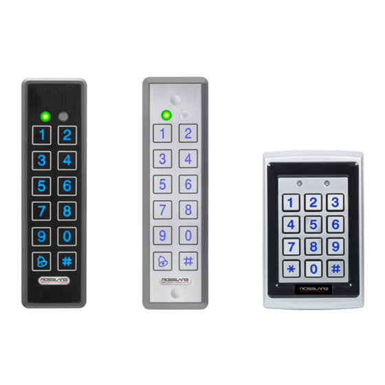
AYC-E/Q60 Series
go
Backlit
PROX & PIN Reader –
Convertible Series with Genuine
™
HID Technology
Installation and Programming Manual
AYC-E60B
AYC-E60N
AYC-Q60
Table of
Contents
Previous
Page
Next
Page
1
2
3
4
5
Advertisement
Table of Contents
Need help?
Do you have a question about the AYC-E60B and is the answer not in the manual?
Ask a question
Questions and answers
Related Manuals for Rosslare AYC-E60B
Intercom System Rosslare AYC-E60 Installation And Programming Manual
Ayc-e/q/t60 family (70 pages)
Card Reader Rosslare CSN SELECT AYC-H6355 Installation And User Manual
Smart card readers/controllers (rev. b) (69 pages)
Card Reader Rosslare CSN SELECT AYC-6355 Series Installation And User Manual
Smart card readers/controllers (rev. b) (69 pages)
Card Reader Rosslare AYC-F60 Series Installation And Programming Manual
Convertible reader with genuine hid technology (66 pages)
Card Reader Rosslare AYC-Q6355 Installation And User Manual
Smart card readers/controllers (rev. b) (69 pages)
Card Reader Rosslare AYC-E60N Installation And Programming Manual
Backlit goprox & pin reader – convertible series with genuine hid technology (66 pages)
Card Reader Rosslare AY-Z12A Installation Manual
Long range multi reader (17 pages)
Card Reader Rosslare AY-Q6250 Installation And Programming Manual
Anti-vandal mifare contactless smart card / pin readers ay-q6x50 series (32 pages)
Card Reader Rosslare AY-U920BT-US Installation And User Manual
Extended long-range uhf-rfid reader with bluetooth ble-id (23 pages)
Card Reader Rosslare AY-R12 Installation Manual
Outdoor rgb illuminated reader (15 pages)
Card Reader Rosslare AY-D09M Installation And Programming Manual
Programmable indoor readers (28 pages)
Card Reader Rosslare Multi-Smart AY-K35 Installation & User Manual
125 khz, 13.56 mhz, bluetooth and nfc (11 pages)
Card Reader Rosslare Anti-Vandal MIFARE AY-Q6 60 Series Installation And User Manual
(38 pages)
Card Reader Rosslare AY-Z12 Installation Manual
Long range multi reader (16 pages)
Card Reader Rosslare MIFARE AY-T6350 Installation And Programming Manual
Contactless smart card / pin readers (29 pages)
Card Reader Rosslare Mifare AY 25 Series Operational Manual
Id read-only proximity reader (16 pages)
This manual is also suitable for:
Ayc-q60 series
Ayc-e60 series
Ayc-e60n
Ayc-q60
Table of Contents
Save PDF
Print
Rename the bookmark
Delete bookmark?
Delete from my manuals?
Login
Sign In
OR
Sign in with Facebook
Sign in with Google
Upload manual
Upload from disk
Upload from URL


Need help?
Do you have a question about the AYC-E60B and is the answer not in the manual?
Questions and answers