
Related Manuals for Rosslare CSN SMART AY-H6355BT


Summary of Contents for Rosslare CSN SMART AY-H6355BT
- Page 1 AY-H6355BT CSN SMART™ Smart Card Readers (Rev. A) Installation and User Manual BLE 4.1...
- Page 2 ROSSLARE. ROSSLARE reserves the right to revise and change this document at any time, without being obliged to announce such revisions or changes beforehand or after the fact.
-
Page 3: Table Of Contents
Table of Contents Table of Contents Introduction ..............7 Installation Kit ................. 8 Technical Specifications ..........9 Mounting ..............10 Wiring Instructions ........... 12 OSDP Operation ............14 Reader Functionality ..........17 Standby Mode ..............17 Programming ................ 17 6.2.1 Entering Programming Mode ............ - Page 4 List of Figures List of Figures Figure 1: Removing the Top Cover ..............10 Figure 2: DIP Switch Compartment ..............15 Figure 3: DIP Switch Settings ................16 AY-H6355BT Installation and User Manual...
- Page 5 List of Tables List of Tables Table 1: Wiring the Unit as a Reader to a Control Panel ........12 Table 2: Reader Programming Menus .............. 18 Table 3: Keypad Transmission Format Option Number ........21 Table 4: Proximity Card Transmission Format Option Number ......26 AY-H6355BT Installation and User Manual...
- Page 6 ROSSLARE exclusive warranty and liability is limited to the warranty and liability statement provided in an appendix at the end of this document.
-
Page 7: Introduction
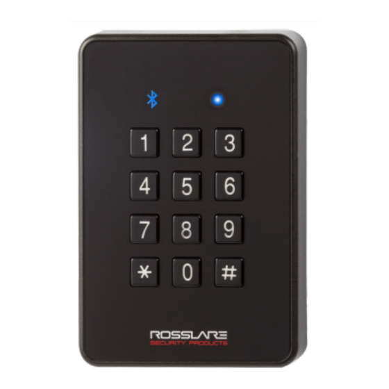
Introduction Introduction The CSN SMART™ AY-H6355BT is an innovative reader from Rosslare geared for quad-play operation: backlit PIN keypad, smart card CSN (13.56 MHz) card reader, NFC-ID read, and BLE-ID smartphone ID read capabilities. Designed with premium components and IP65 mechanicals, it works well indoors and outdoors. -
Page 8: Installation Kit
Introduction Installation Kit The installation kit consists of the following items to be used during the installation procedure: 1 self-adhesive mounting label template 2 mounting screws and 2 screw anchors 1 Torx key tool 1 Torx security screw AY-H6355BT Installation and User Manual... -
Page 9: Technical Specifications
Outdoor Usage Weather-resistant, UV-resistant, epoxy-potted, suitable for indoor and outdoor use * Measured using a Rosslare MIFARE Classic EV1 (ISO card). Read range with other credential technologies may vary. Range also depends on electrical environment and proximity to metal. Physical Characteristics Dimensions (H x W x D) 110.7 ×... -
Page 10: Mounting
Mounting Mounting Before mounting, you should determine the best location for the reader. To mount the units: 1. Peel off the back of the self-adhesive mounting label template and place it at the required mounting location. 2. Using the template as a guide, drill two holes (sizes indicated on the template) used for mounting the back plate onto the surface. - Page 11 Mounting 7. Align the two holes of the reader with those drilled in the wall and firmly attach the reader to the wall with two screws, whose size is indicated on the template. 8. Relocate the front cover onto the reader. The reader can also be mounted using strong epoxy glue.
-
Page 12: Wiring Instructions
Wiring Instructions Wiring Instructions The units are supplied with a 10-conductor 5-m (16-ft) pigtail with exposed wires coated with solder. To connect the unit as a reader to an access control unit: 1. Select the appropriate connections according to Table 1. 2. - Page 13 Wiring Instructions 4. Trim and insulate the ends of all unused conductors individually. Do not short any unused wires together. • The individual wires from the reader are color coded according the Wiegand standard. • When using a separate power supply for the reader, this supply and that of the controller must have a common ground.
-
Page 14: Osdp Operation
OSDP Operation OSDP Operation • In OSDP mode, all control lines (Inputs/Outputs) are disabled. • In OSDP mode, if a connection is not established or lost with the controller, the right LED flashes yellow continuously. The reader is compatible with all reader-related OSDP commands. The reader address is set using DIP switches on the back of the reader. -
Page 15: Figure 2: Dip Switch Compartment
OSDP Operation Figure 2: DIP Switch Compartment AY-H6355BT Installation and User Manual... -
Page 16: Figure 3: Dip Switch Settings
OSDP Operation Figure 3 shows the DIP switch settings, which are also described below. Figure 3: DIP Switch Settings DIP Switch 1 This switch is used to select the reader output (Wiegand or OSDP): Off = Wiegand On = OSDP ... -
Page 17: Reader Functionality
Reader Functionality Reader Functionality Upon power on, the unit flashes yellow, then blue, and then orange, each for 1 second and a beep is heard for each color. Standby Mode The default mode of the reader is Standby mode. In Standby mode, the unit is ready to receive data from an entered PIN code or from a presented proximity card, NFC-ID, and BLE-ID. -
Page 18: Table 2: Reader Programming Menus
Table 2: Reader Programming Menus Menu Description Default Selecting Keypad Transmission Format Single Key, 6-Bit Wiegand (Rosslare Format) Single Key, 6-Bit Wiegand with Nibble + Parity Bits Single Key, 8-Bit Wiegand, Nibbles Complemented 4 Keys Binary + Facility Code, Wiegand 26-Bit... -
Page 19: Entering Programming Mode
Reader Functionality 6.2.1 Entering Programming Mode To reach the Programming Menu System, the unit must first be placed into Programming mode. • The factory 4-digit Programming code is 1234. • If a Programming code is not entered within 20 seconds, the unit returns to Standby mode. -
Page 20: Selecting Keypad Transmission Format
Reader Functionality 6.2.3 Selecting Keypad Transmission Format The AYC-x6355 has nine different keypad transmission formats. See Table 3 in Section 6.2.3.1 for more information on keypad transmission formats. • Only one keypad transmission format can be active at any one time. -
Page 21: Table 3: Keypad Transmission Format Option Number
More information on each of the different keypad transmission formats is available below and on the following pages. Option 1: Single Key, Wiegand 6-Bit (Rosslare Format) Each key press immediately sends 4 bits with 2 parity bits added – even parity for the first 3 bits and odd parity for the last 3 bits. - Page 22 Reader Functionality Option 2: Single Key, Wiegand 6-Bit Nibble and Parities Each key press immediately sends 4 bits with 2 parity bits added – even parity for the first 3 bits and odd parity for the last 3 bits. 0 = 0 0000 1 6 = 1 0110 0 1 = 0 0001 0 7 = 1 0111 1...
- Page 23 Reader Functionality If the entry of the 4-digit keypad PIN code is disrupted and no number key is pressed within 5 seconds, the keypad clears the PIN code entry buffer, generates a beep and is ready to receive a new 4-digit keypad PIN code.
- Page 24 Reader Functionality (EP) FFFF FFFF AAAA AAAA AAAA AAAA (OP) Where: EP = Even parity for first 12 bits OP = Odd parity for last 12 bits F = 8-bit Facility code A = 16-bit code generated from keypad Option 6: 6 Keys BCD and Parity Bits, Wiegand 26-Bit Option 6 sends buffer of 6 keys, adds parity and sends a 26-Bit Binary BCD message.
-
Page 25: Selecting Proximity Card Transmission Format
Reader Functionality the PIN code. The data is sent across the two data output lines as binary data in Clock & Data format. If * or # key is pressed during PIN code entry, the keypad clears the PIN code entry buffer, generates a beep, and is ready to receive a new keypad PIN code. -
Page 26: Table 4: Proximity Card Transmission Format Option Number
Reader Functionality 3. Enter the appropriate option number for the proxy card transmission format that you wish to select: 1 – Wiegand 26-Bit 2 – Clock & Data 3 – Wiegand 32-Bit 4 – Wiegand 32-Bit Reversed Byte ... - Page 27 Reader Functionality Option 1: Wiegand 26-Bit In this mode, 3 LSB bytes from the card serial number (UID) are transmitted in Wiegand 26-Bit format. Two parity bits are added. An even parity bit is sent first, followed by three bytes of card data, and by an odd parity bit.
- Page 28 Reader Functionality Where: D = 1 (LSB) byte of card serial number C = 2 byte of card serial number B = 3 byte of card serial number A = 4 (MSB) byte of card serial number Option 5: Wiegand 34-Bit In this mode, 4 LSB bytes of card serial number are transmitted in Wiegand 34-Bit format.
-
Page 29: Changing The Programming Code
Reader Functionality Option 7: Wiegand 56-Bit In this mode, 7 bytes of card serial number are transmitted in Wiegand 56-Bit format. No parity bits are added. AAAA AAAA BBBBBBBB CCCCCCCC DDDDDDDD EEEEEEEE FFFFFFFF GGGGGGGG Option 8: Wiegand 64-Bit In this mode, 8 bytes of card serial number are transmitted in Wiegand 64-Bit format. -
Page 30: Changing The Facility Code
Reader Functionality 6.2.6 Changing the Facility Code • The Facility code can be in the range of 000 to 255. • The default Facility code is 0. To change the Facility code: 1. Enter Programming mode. green 2. Press 4 to enter Menu 4. The right LED turns yellow. -
Page 31: Setting The Backlight Behavior
Reader Functionality 3. Enter one of the following codes: 0 – All formats (default) 1 – 14443A 2 – 14443B 3 – 15693 4 – Felica 5 – China ID 6 – Topaz You hear three beeps. -
Page 32: Return To Factory Default Settings
Reader Functionality 6.2.9 Return to Factory Default Settings You must be very careful before using this command! This erases the entire memory and return all codes to their factory default setting. To return to factory default settings: 1. Enter Programming mode. green 2. -
Page 33: Declaration Of Conformity
Declaration of Conformity Declaration of Conformity This device complies with Part 15 of the FCC Rules. Operation is subject to the following two conditions: This device may not cause harmful interference. This device must accept any interference received, including interference that may cause undesired operation. -
Page 34: Limited Warranty
The full ROSSLARE Limited Warranty Statement is available in the Quick Links section on the ROSSLARE website at www.rosslaresecurity.com. Rosslare considers any use of this product as agreement to the Warranty Terms even if you do not review them. AY-H6355BT Installation and User Manual... - Page 35 Tel: +86-755-8610 6842 Fax: +86-755-8610 6101 Rosslare Security Products, Inc. support.cn@rosslaresecurity.com Southlake, TX, USA India Toll Free: +1-866-632-1101 Local: +1-817-305-0006 Rosslare Electronics India Pvt Ltd. Fax: +1-817-305-0069 Tel/Fax: +91-20-40147830 support.na@rosslaresecurity.com Mobile: +91-9975768824 Europe sales.in@rosslaresecurity.com Rosslare Israel Ltd. 22 Ha'Melacha St., P.O.B. 11407...
Need help?
Do you have a question about the CSN SMART AY-H6355BT and is the answer not in the manual?
Questions and answers