
Related Manuals for Rosslare AYC-E60


Summary of Contents for Rosslare AYC-E60
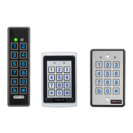
- Page 1 AYC-E/Q/T60 Family Backlit PROX & PIN Reader – Convertible Series with Genuine ™ HID Technology Installation and Programming Manual AYC-E60 AYC-Q60 AYC-T60...
- Page 2 ROSSLARE. ROSSLARE reserves the right to revise and change this document at any time, without being obliged to announce such revisions or changes beforehand or after the fact.
-
Page 3: Table Of Contents
5.2.4 Keypad Transmission Format Option Number ....... 25 5.2.5 Selecting HID Prox Card Transmission Format ....... 30 5.2.6 Selecting Rosslare Proximity Card Transmission Format ....30 5.2.7 Changing the Programming Code ..........32 5.2.8 Changing the Facility Code ............33 5.2.9... - Page 4 Table of Contents 5.2.11 Return to Factory Default Settings ..........35 5.2.12 Replacing a Lost Programming Code ..........35 Controller Functionality..........36 Normal, Secure, and Master Users .......... 36 Modes of Operation .............. 37 6.2.1 Normal Mode ................37 6.2.2 Bypass Mode ................
- Page 5 Setting the Lockout Feature ............55 6.10.12 Setting the Backlight Behavior ............56 6.10.13 Selecting the Rosslare Proximity and HID Prox Format ....56 6.10.14 Enrolling Primary and Secondary Codes ........57 6.10.15 Deleting Primary and Secondary Codes ......... 61 6.10.16...
- Page 6 List of Figures List of Figures Figure 1: Drilling & Mounting Template for AYC-E60 ........14 Figure 2: Drilling & Mounting Template for AYC-T60 ........14 Figure 3: Drilling & Mounting Template for AYC-Q60 ........16 Figure 4: Controller Application Wiring Diagram ..........18 Figure 5: Auxiliary Output Connection with Internal Power ......
- Page 7 List of Tables List of Tables Table 1: Wiring Colors ..................17 Table 2: Reader Programming Menu ............... 22 Table 3: Keypad Transmission Format .............. 25 Table 4: Controller Programming Menu ............42 Table 5: Quick Reference Guide for Auxiliary Mode Setting ......50 AYC-E/Q/T60 Family Installation and Programming Manual...
- Page 8 The use of the software associated with the system and/or product, if applicable, is subject to the terms of the license provided as part of the purchase documents. ROSSLARE exclusive warranty and liability is limited to the warranty and liability statement provided in an appendix at the end of this document.
-
Page 9: Introduction
If the unit is connected to a standard access control unit, then it functions as a reader. If the unit is connected to a Rosslare secured intelligent power supply such as the PS-A25T, PS-C25T, or PS-C25TU, it functions as a 500 user secured standalone controller. -
Page 10: Reader
1.1.1 Reader Programmable keypad transmission format LED control input Programmable Facility code Rosslare proximity card transmission formats: Clock & Data Wiegand 26-Bit Card + PIN HID Prox Card Transmission Format Wiegand (outputs per format on the card) ... -
Page 11: Box Content
(power to lock) or fail secure (power to open) functions Request-to-Exit (REX) button – normally open type. Switch is closed when pressed Door monitor switch Rosslare accessories can be found on www.rosslaresecurity.com. AYC-E/Q/T60 Family Installation and Programming Manual... -
Page 12: Technical Specifications
Up to 150 m (500 ft) using an 18-AWG cable Controller Max. Proximity Card Read Rosslare proximity: E – 40 mm (1.57 Range* in.), Q – 45 mm (1.77 in.), T – 40 mm (1.57 in.) HID Prox: E – 40 mm (1.57 in.), Q – 45 mm (1.77 in.), T –... - Page 13 E: 143 g (5.04 oz) Q: 480 g (16.93 oz) T: 121 g (4.27 oz) * Measured using a Rosslare proximity card or equivalent. Range also depends on electrical environment and proximity to metal. AYC-E/Q/T60 Family Installation and Programming Manual...
-
Page 14: Installation
Figure 2). For US Gang Box mounting, no drilling is necessary. Figure 1: Drilling & Mounting Figure 2: Drilling & Mounting Template for AYC-E60 Template for AYC-T60 2. When the unit is used as a reader, route the interface cable from the AYC-E/T60 to the controller. -
Page 15: Mounting The Ayc-Q60
Installation 3. When the unit is used as a secured controller, route the interface cable from the AYC-E/T60 to a Rosslare secured series intelligent power supply. 4. Screw the AYC-E/T60 to its mounting location. 5. Return the AYC-E/T60 front cover to the mounted back plate. -
Page 16: Figure 3: Drilling & Mounting Template For Ayc-Q60
Installation Figure 3: Drilling & Mounting Template for AYC-Q60 5. Drill an additional 10-mm ( ”) hole for the cable. When installing the reader on a metallic surface, cover the inside of the hole with a grommet or electrical tape. 6. -
Page 17: Wiring Instructions
Wiring Instructions Wiring Instructions The unit is supplied with 56-cm (22”) pigtail, having a 6-conductor cable. To connect the unit to the controller: 1. Prepare the unit's cable by cutting the cable jacket back 3.2 cm (1¼”) and stripping the wire 1.3 cm (½”). 2. -
Page 18: Figure 4: Controller Application Wiring Diagram
Wiring Instructions Figure 4 shows the wiring for the Controller Application using a secured intelligent power supply. Figure 4: Controller Application Wiring Diagram AYC-E/Q/T60 Family Installation and Programming Manual... -
Page 19: Figure 5: Auxiliary Output Connection With Internal Power
Wiring Instructions Figure 5 shows the auxiliary output connection using internal power. Figure 5: Auxiliary Output Connection with Internal Power Figure 6 shows the auxiliary output connection using the external power. Figure 6: Auxiliary Output Connection with External Power AYC-E/Q/T60 Family Installation and Programming Manual... -
Page 20: Figure 7: Reader Application Wiring Diagram
Wiring Instructions Figure 7 shows how to wire a reader to an access control panel. Figure 7: Reader Application Wiring Diagram AYC-E/Q/T60 Family Installation and Programming Manual... -
Page 21: Reader Functionality
Reader Functionality Reader Functionality The AYC-E/Q/T60 series can function both as a reader and as a controller. If the unit is connected to standard access controller, it functions as a reader, indicated by one beep immediately after power- on reset. The following explains how the AYC-E/Q/T60 series functions as a reader. -
Page 22: Table 2: Reader Programming Menu
Table 2: Reader Programming Menu Menu Description Default Selecting Keypad Transmission Format Single Key, Wiegand 6-Bit (Rosslare Format) Single Key, Wiegand 6-Bit with Nibble + Parity Bits Single Key, Wiegand 8-Bit, Nibbles Complemented 4 Keys Binary + Facility code, Wiegand 26-Bit... -
Page 23: Entering Programming Mode
Reader Functionality 5.2.1 Entering Programming Mode To reach the Programming Menu System, the AYC-E/Q/T60 must first be placed into Programming mode. To enter Programming mode: 1. Press # four times. Mode/Transmit Door/Program Transmit LED turns off. Program LED turns red. 2. -
Page 24: Selecting Keypad Transmission Format
Reader Functionality 5.2.3 Selecting Keypad Transmission Format The AYC-E/Q/T60 has nine different keypad transmission formats from which to select. To select the key pad transmission format: Mode/Transmit Door/Program 1. Enter Programming mode. Green 2. Press 1 to enter Menu 1. The Transmit LED turns red. -
Page 25: Keypad Transmission Format Option Number
5.2.4.1 Option 1: Single Key, Wiegand 6-Bit (Rosslare Format) Each key press immediately sends 4 bits with 2 parity bits added – even parity for the first 3 bits and odd parity for the last 3 bits. - Page 26 Reader Functionality 5.2.4.2 Option 2: Single Key, Wiegand 6-Bit Nibble and Parities Each key press immediately sends 4 bits with 2 parity bits added – even parity for the first 3 bits and odd parity for the last 3 bits. 0 = 0 0000 1 6 = 1 0110 0 1 = 0 0001 0...
- Page 27 Reader Functionality If * or # are pressed during PIN code entry, the keypad clears the PIN code entry buffer, generates a beep, and is ready to receive a new 4- digit keypad PIN code. If the entry of the 4-digit keypad PIN code is disrupted and no number key is pressed within 5 seconds, the keypad clears the PIN code entry buffer, generates a beep, and is ready to receive a new 4-digit keypad PIN code:...
- Page 28 Reader Functionality (EP) FFFF FFFF AAAA AAAA AAAA AAAA (OP) Where: EP = Even parity for first 12 bits OP = Odd parity for last 12 bits F = 8-Bit Facility code A = 16-Bit code generated from keyboard 5.2.4.6 Option 6: 6 Keys BCD and Parity Bits, Wiegand 26-Bit This option sends buffer of 6 keys, adds parity, and sends a 26-bit BCD message.
- Page 29 Reader Functionality When a key is pressed, DATA1 is pulled "low" until the key is released at which point DATA1 is set to "high". This allows the controller to detect the duration of the key press. The MD-P64 interface unit outputs the data received to 7 outputs emulating a keyboard.
-
Page 30: Selecting Hid Prox Card Transmission Format
5.2.6 Selecting Rosslare Proximity Card Transmission Format The AYC-E/Q/T60 can read Rosslare proximity cards (125 kHz) and can output Rosslare proximity card data as Wiegand 26-Bit, Clock & Data, and Wiegand + PIN. To select the Rosslare prox imity card transmission format: Door/Program 1. - Page 31 Reader Functionality Mode/Transmit Door/Program You hear three beeps. The system returns to Transmit mode. If an incorrect option is entered, the reader returns to Transmit mode and the keypad transmission format remains unchanged. 5.2.6.1 "Wiegand Card + PIN" Transmission Format This unique mode is intended to let host controllers get card and keypad data simultaneously.
-
Page 32: Changing The Programming Code
Reader Functionality Where: A = The first key entered D = Fourth key entered B = Second key entered E = Fifth key entered C = Third key entered EP = Even parity for first 12 bits OP = Odd parity for last 12 bits If the PIN code is less than 5 digits, all the most significant nibbles are filled with 0. -
Page 33: Changing The Facility Code
Reader Functionality • The Programming code cannot be erased; the code 0000 is invalid and does not erase the Programming code. • The factory default 4-digit Programming code is 1234. 5.2.8 Changing the Facility Code To change the Facility code: 1. -
Page 34: Setting The Reader Format
3. Enter the appropriate option number for the reader format: 61 for Rosslare proximity 62 for HID Prox 63 for Rosslare proximity and HID Prox (default) Mode/Transmit Door/Program You hear three beeps. The system returns to Transmit mode. -
Page 35: Return To Factory Default Settings
Reader Functionality 5.2.11 Return to Factory Default Settings You must be very careful before using this command! This erases the entire memory and returns all codes to their factory default setting. To return to factory default settings: 1. Enter Programming mode. Mode/Transmit Door/Program Green... -
Page 36: Controller Functionality
Controller Functionality The AYC-E/Q/T60 series can function both as a reader and as a controller. If the unit is connected to a Rosslare secured series intelligent power supply, it functions as a controller indicated by two beeps immediately after power-on reset. -
Page 37: Modes Of Operation
Controller Functionality Secure User – A Secure User must have a Primary and Secondary code programmed; the two codes must not be the same. The Secure User can gain access when the AYC-E/Q/T60 is in any of its three modes of operation. In Normal mode, the Secure User must use the Primary code to gain entry. -
Page 38: Secure Mode
Controller Functionality 6.2.3 Secure Mode Door/Program The Mode LED is red. Mode/Transmit Only Secure and Master Users can access the premises during the Secured mode. A Secure User must enter their Primary and Secondary codes to gain entry. After entering their Primary code, the Door LED flashes green for 10 seconds, during which the Secondary code must be entered. -
Page 39: Changing From Normal Mode To Bypass Mode
Controller Functionality 2. Press # to confirm the mode change. Door/Program The Mode LED turns green. Mode/Transmit Green 6.3.3 Changing from Normal Mode to Bypass Mode See Section 6.10.7 to create/modify the Normal/Bypass code. To change from Normal to By pass mode: Mode/Transmit Door/Program 1. -
Page 40: Auxiliary Input And Output
Controller Functionality Auxiliary Input and Output For optimum usability in different applications, the controller’s auxiliary input and output can be configured in 10 different modes of operation. Door Alarms Door alarms can be generated by connecting the Auxiliary Input to a Door Position Switch. -
Page 41: Rex Function
Controller Functionality REX Function The REX button is connected to a Rosslare secured series intelligent power supply. The REX button must be located inside the premises to be secured and is used to open the door without the use of a PIN code. -
Page 42: Programming The Ayc-E/Q/T60
Changing Normal/Bypass Code Changing Door Release Time 0004 Defining auxiliary inputs/outputs 2004 Set Lockout 4000 Backlight Behavior 5100 Rosslare proximity/HID Prox 6300 format Enrolling PIN Code Deleting PIN Code Code assignment with strike/auxiliary Return to factory defaults/Change PIN code Length... -
Page 43: Entering Programming Mode
Controller Functionality You will find a complete description and instructions for each of the above menu items on the following subsections. 6.10.1 Entering Programming Mode To enter Programming mode: 1. Press # twice within 2 seconds. Door/Program The Mode LED turns off and the Mode/Transmit Door LED turns red 2. -
Page 44: Changing Lock Strike Code
Controller Functionality 6.10.3 Changing Lock Strike Code The Lock Strike code is mainly used as a method to quickly test the Lock Strike Relay during installation. When the first user is added to the controller, the default Lock Strike code is automatically deleted. Once the code is programmed again, it is not deleted with the entry of additional User codes. -
Page 45: Changing The Programming Code
Controller Functionality Mode/Transmit Door/Program The Mode LED turns orange. Orange Green 3. Enter the new code you wish to set as the Auxiliary code. You hear three beeps. Mode/Transmit Door/Program Green The system returns to Normal mode. • Auxiliary code does not work in the Secure mode. •... -
Page 46: Changing The Normal/Secure Code
Controller Functionality • The Programming code cannot be erased; the code 0000 is invalid and does not erase the Programming code. • The factory default 4-digit Programming code is 1234. 6.10.6 Changing the Normal/Secure Code To change the Normal/ Secure code: Door/Program 1. -
Page 47: Setting Fail Safe/Secure Operation, Tamper Siren And Lock Strike Release Time
Controller Functionality 3. There are four different ways to program the Normal/Bypass code and door chime: Disable both Bypass code and the door chime. Enter the code 0000. Disable Bypass code and enable the door chime. Enter the code 0001. ... -
Page 48: Defining The Auxiliary Input And Output
Controller Functionality Construct a code using the following instructions: First Digit For Fail Secure Operation, the first digit should be 0. For Fail Safe Operation the first digit should be 1. Second Digit Siren Time in minutes (1-9, 0-disabled) Third and Fourth Digits ... - Page 49 Controller Functionality The Mode LED flashes green. Mode/Transmit Door/Program Green Green 3. Construct a code using the following instructions: Auxiliary Mode Auxiliary Setting Auxiliary Mode In addition to the Lock Strike Relay and Lock Strike REX, the AYC-E/Q/T60 features an Auxiliary Input. The Auxiliary mode defines the function of the Auxiliary Input.
-
Page 50: Table 5: Quick Reference Guide For Auxiliary Mode Setting
Controller Functionality Table 5: Quick Reference Guide for Auxiliary Mode Setting Auxiliary Auxiliary Input Auxiliary Output Auxiliary Auxiliary Settings Mode Function Activated by Relay (in seconds) AUX REX Valid code or AUX REX N.O. 01 to 99 Aux. relay release time 00 Aux. -
Page 51: 6.10.10 Detailed Reference Guide
Controller Functionality 6.10.10 Detailed Reference Guide The following are brief descriptions of each auxiliary mode. To implement the features of each mode, refer to Section 6.10.9. 6.10.10.1 Auxiliary Mode 0 Auxiliary input function: Activates the auxiliary output Auxiliary output activated by: Valid user code, Auxiliary code, Auxiliary input For example, in Auxiliary Mode 0, the controller can function as a two-door controller. - Page 52 Controller Functionality the auxiliary relay is to be activated. The auxiliary input can switch the mode of operation of the controller between Normal and Secure modes. By connecting a switch timer or alarm system output to the auxiliary input, the controller can be automatically switched from Normal mode (during office hours) to Secure mode (after office hours).
- Page 53 Controller Functionality 6.10.10.6 Auxiliary Mode 5 Auxiliary input function: Door Monitor Auxiliary output activated by: Shunt (explanation below) For example, in Auxiliary Mode 5, the controller is capable of shunting an alarm system. In this mode, the auxiliary input is to be wired to the magnetic contact switch on the door.
-
Page 54: Auxiliary Mode
Controller Functionality and if the door does not close prior to the end of this period, the controller activates the auxiliary relay. The auxiliary setting defines the door-ajar time. 6.10.10.9 Auxiliary Mode 8 Auxiliary input function: Green LED control Auxiliary output activated by: Valid user code, Auxiliary code For example, in Auxiliary Mode 8, the controller can function as a two-door controller and also provide indicator functionality control. -
Page 55: 6.10.11 Setting The Lockout Feature
Controller Functionality 6.10.11 Setting the Lockout Feature If the controller is presented with wrong codes consecutively several times, the unit goes into Lockout mode. When a lockout occurs, the controller keypad and reader are locked so no codes can be entered until the set lockout period expires. During Lockout, Mode LED is off, the door LED flashes red, and the controller beeps every two seconds. -
Page 56: 6.10.12 Setting The Backlight Behavior
(Mode LED also goes on), after which it returns to a dimmed level 6.10.13 Selecting the Rosslare Proximity and HID Prox Format The controller allows you to select the Rosslare proximity and HID Prox format. To select the Rosslare prox imity and HID Prox format: Door/Program 1. -
Page 57: 6.10.14 Enrolling Primary And Secondary Codes
Controller Functionality 3. Enter one of the following codes: 6100 – Rosslare Proximity 6200 – HID Prox 6300 – Rosslare Proximity + HID Prox (default) 6.10.14 Enrolling Primary and Secondary Codes Primary codes Primary codes can only be enrolled to an empty user slot, meaning a slot where there is no existing primary code. - Page 58 Controller Functionality Code Search Method The Code Search Method is mainly used when enrolling a user’s Secondary code and the User Slot code is unknown. The Code Search method only works if a user’s Primary code is already enrolled but the Secondary code is not (see Section 6.10.14.2).
- Page 59 Controller Functionality If the selected slot already has a Mode/Transmit Door/Program Primary code but no Secondary Orange code, the Mode LED flashes red, indicating that the controller is ready to accept a Secondary code. Door/Program If the selected slot already has a Mode/Transmit Green Primary and Secondary code, you...
- Page 60 Controller Functionality 6.10.14.2 Enrolling Secondary Codes using the Code Search Method The Code Search feature enables you to quickly enroll a Secondary code to a user who already has a Primary code. To enroll secondary codes using the Code Search method: Door/Program 1.
-
Page 61: Deleting Primary And Secondary Codes
Controller Functionality 5. Perform one of the following: Enter the PIN code to be used as the Secondary code. Present the user card to be used as the Secondary code. If the Secondary code is valid, the controller beeps three times and returns to Normal mode. - Page 62 Controller Functionality The Mode LED flashes red Mode/Transmit Door/Program indicating the controller is Orange waiting for the Programming code to confirm the deletion. If the user slot is empty, you hear a long beep and the AYC- E/Q/T60 returns to Normal mode. 4.
-
Page 63: 6.10.16 Relay Codes Assignment
Controller Functionality The controller is now waiting for the Primary code of the user you want to delete. 4. Perform one of the following: Enter the PIN code of the Primary code belonging to the user you want to delete. ... - Page 64 Controller Functionality 6.10.16.1 Relay Code Assignment using the Standard Method To assign relay code using the Standard method: Door/Program 1. Enter Programming mode. Mode/Transmit Green 2. Press 9 to enter Menu 9. Mode/Transmit Door/Program The Mode LED turns green and the Door LED turns orange.
- Page 65 Controller Functionality Mode/Transmit Door/Program The Mode LED turns green and the Door LED turns orange. Green Orange 3. Enter 000 for user slot access. The Door LED flashes orange. Mode/Transmit Door/Program Green Orange The controller is now waiting for the primary code of the user. 4.
-
Page 66: 6.10.17 Pin Code Length/Factory Default Settings
Controller Functionality 6.10.17 PIN Code Length/Factory Default Settings You must be very careful before using this command! Changing the PIN code length also erases the entire memory contents, including all user and special codes, and returns all codes to their factory-default settings. To change the PIN code length: Mode/Transmit Door/Program... -
Page 67: 6.10.18 Replacing A Lost Programming Code
Controller Functionality 6.10.18 Replacing a Lost Programming Code The AYC-E/Q/T60 must be in Normal mode; otherwise, this does not work. Make sure that the Mode LED is green before proceeding. 1. Remove power from the Power Supply Unit. 2. Press the REX button on the Power Supply Unit. 3. -
Page 68: Declaration Of Conformity
Declaration of Conformity Declaration of Conformity This device complies with Part 15 of the FCC Rules. Operation is subject to the following two conditions: This device may not cause harmful interference. This device must accept any interference received, including ... -
Page 69: Limited Warranty
The full ROSSLARE Limited Warranty Statement is available in the Quick Links section on the ROSSLARE website at www.rosslaresecurity.com. Rosslare considers any use of this product as agreement to the Warranty Terms even if you do not review them. AYC-E/Q/T60 Family Installation and Programming Manual... - Page 70 +86 755 8610 6842 Fax: +86 755 8610 6101 Rosslare Security Products, Inc. support.cn@rosslaresecurity.com Southlake, TX, USA Toll Free: +1-866-632-1101 India Local: +1-817-305-0006 Rosslare Electronics India Pvt Ltd. Fax: +1-817-305-0069 Tel/Fax: +91 20 40147830 support.na@rosslaresecurity.com Mobile: +91 9975768824 Europe sales.in@rosslaresecurity.com Rosslare Israel Ltd.
Need help?
Do you have a question about the AYC-E60 and is the answer not in the manual?
Questions and answers