
Subscribe to Our Youtube Channel
Related Manuals for Pepperl+Fuchs IUT-F190-R4-V1 Series


Summary of Contents for Pepperl+Fuchs IUT-F190-R4-V1 Series
- Page 1 FACTORY AUTOMATION MANUAL IUH-F190-V1-* IUT-F190-R4-V1* UHR Read/Write Head for IDENTControl...
- Page 2 IUH-F190-V1-*, IUT-F190-R4-V1* With regard to the supply of products, the current issue of the following document is ap- plicable: The General Terms of Delivery for Products and Services of the Electrical Indus- try, published by the Central Association of the Electrical Industry (Zentralverband Elektrotechnik und Elektroindustrie (ZVEI) e.V.) in its most recent version as well as the supplementary clause: "Expanded reservation of proprietorship"...
-
Page 3: Table Of Contents
IUH-F190-V1-*, IUT-F190-R4-V1* Introduction................. 7 Content of this Document ..............7 Target Group, Personnel..............7 Symbols Used ..................8 Certificates and Approvals ............9 Declaration of Conformity (RE Directive 2014/53/EU)...... 9 FCC-Information................... 9 IC-Information..................10 UL Information..................10 Additional Country-Specific Approvals ........... 10 Product Description .............. - Page 4 IUH-F190-V1-*, IUT-F190-R4-V1* Countries of Use.................17 3.3.1 European Union ................17 3.3.2 Argentina..................18 3.3.3 Australia ................... 18 3.3.4 Brazil ....................18 3.3.5 Canada .................... 18 3.3.6 China....................18 3.3.7 Hong Kong ..................19 3.3.8 India ....................19 3.3.9 Japan ....................19 3.3.10 Colombia..................
- Page 5 IUH-F190-V1-*, IUT-F190-R4-V1* Mounting ..................... 28 4.3.1 Room Orientation................29 4.3.2 Minimum Distances ................. 30 4.3.3 Polarization ..................30 Connection ..................31 EMC Concept..................32 Commissioning................. 33 Definitions................... 33 5.1.1 Display..................... 33 5.1.2 Legend..................... 33 Sensor Settings.................. 34 Operation via the Command Interface ..........34 Operation...................
- Page 6 IUH-F190-V1-*, IUT-F190-R4-V1* Service and Maintenance ............65 Troubleshooting................ 66 Appendix ................... 67 Dimensions ..................67 ASCII Table ..................67 Detection Range .................68...
-
Page 7: Introduction
IUH-F190-V1-*, IUT-F190-R4-V1* Introduction Introduction Content of this Document This document contains information required to use the product in the relevant phases of the product life cycle. This may include information on the following: Product identification Delivery, transport, and storage Mounting and installation Commissioning and operation Maintenance and repair Troubleshooting... -
Page 8: Symbols Used
IUH-F190-V1-*, IUT-F190-R4-V1* Introduction Symbols Used This document contains symbols for the identification of warning messages and of informative messages. Warning Messages You will find warning messages, whenever dangers may arise from your actions. It is mandatory that you observe these warning messages for your personal safety and in order to avoid property damage. -
Page 9: Certificates And Approvals
Note! A Declaration of Conformity can be requested from the manufacturer or downloaded from www.pepperl-fuchs.com. The product manufacturer, Pepperl+Fuchs GmbH, 68307 Mannheim, has a certified quality assurance system that conforms to ISO 9001. ISO9001 FCC-Information FCC ID: IREIUHF190V1B This device complies with Part 15 of the FCC Rules. -
Page 10: Ic-Information
, voltage range is 20 ... 30 V . Supply must be PELV (Protective Extra Low Voltage). This is the case if Pepperl+Fuchs IDENTControl control interface is used. Protection class IP67 is not included in the UL approval. The protection class is tested by Pepperl + Fuchs GmbH. -
Page 11: Product Description
IUH-F190-V1-*, IUT-F190-R4-V1* Product Description Product Description RFID Frequency Bands The following diagram shows the position of the different frequency bands used for RFID. The read/write heads described in this manual operate in the frequency range from 865 MHz ... 868 MHz and from 902 MHz ... 928 MHz, highlighted in color. 1000 10000 Frequency... -
Page 12: Memory Structure Of A Tag Acc. To Epc Gen 2
IUH-F190-V1-*, IUT-F190-R4-V1* Product Description 3.2.3 Memory Structure of a Tag in Accordance with EPC Gen 2 (ISO/IEC 18000-63) [7:0] DSFID [7:0] Commands Read / write head Memory module [15:0] SR/ER Bank 11 USER [31:16] SW/EW Bank 10 SF/EF SS/ES Bank 01 UII/EPC Optional XPC_W2 [15:0]... - Page 13 IUH-F190-V1-*, IUT-F190-R4-V1* Product Description Bank 00: Password Management The segment Bank 00 contains the password management information, comprising the access password and the kill password. The read/write head manages the kill password with the standard read/write commands SW and SR. The access password is not supported. See "Single Read Words SR"...
-
Page 14: Electronic Product Code (Epc)
IUH-F190-V1-*, IUT-F190-R4-V1* Product Description 3.2.4 Electronic Product Code (EPC) The electronic product code is a unique identifier in the form of a sequence of numbers. The number sequence has a set structure and a length of 64 bits, 80 bits, 96 bits, or longer (depending on the EPC Ident number used). -
Page 15: Dense Reader Mode (Drm)
IUH-F190-V1-*, IUT-F190-R4-V1* Product Description 100 % 90 % 80 % 70 % 60 % 50 % 40 % 30 % 20 % Foam material Film 10 % Cardboard (dry) Cardboard (wet) Wood (dry) Glass Metal Material underground Material between transponder and read / write head 3.2.6 Dense Reader Mode (DRM) -
Page 16: Frequency Hopping Spread Spectrum
IUH-F190-V1-*, IUT-F190-R4-V1* Product Description 3.2.7 Frequency Hopping Spread Spectrum With FHSS (Frequency Hopping Spread Spectrum), the information to be transmitted is distributed successively through multiple channels. Only one frequency channel is used at any one time. This results in a larger bandwidth for the entire signal, in spite of the fact that each channel has a smaller bandwidth. -
Page 17: Relevant Standards For Uhf
IUH-F190-V1-*, IUT-F190-R4-V1* Product Description 3.2.8 Relevant Standards for UHF European radio standards: EN 300220 and EN 302208 Usage recommendations for RFID type labels, information about recycling, installation of readers and antennae: ISO/IEC TR 24729 parts 1-4 Installation and commissioning of UHF-RFID systems: ETSI TR 102436 Description of air interface: EPC Gen 2 (ISO/IEC 18000-63) Countries of Use Note! -
Page 18: Argentina
IUH-F190-V1-*, IUT-F190-R4-V1* Product Description 3.3.2 Argentina The regulations for the UHF frequency range in Argentina are the same as the regulations for the UHF frequency range in the USA. See chapter 3.3.18. 3.3.3 Australia In Australia, the use of RFID in the UHF range is regulated as follows: UHF wavelength: 920 MHz ... -
Page 19: Hong Kong
IUH-F190-V1-*, IUT-F190-R4-V1* Product Description Number of channels: 16 Channels used: 2, 3, 4, ... 17 Center frequencies: 920.125 MHz + (M x 0.25) MHz All 16 channels are always used. 3.3.7 Hong Kong The regulations for the UHF frequency range of 865 MHz to 868 MHz in Hong Kong are the same as the regulations for the UHF frequency range in the European Union. -
Page 20: Mexico
IUH-F190-V1-*, IUT-F190-R4-V1* Product Description UHF wavelength: 919 MHz 923 MHz Radiated Power: 3 800 mW ; Default = 80 mW Channel bandwidth: 500 kHz Channel spacing: 500 kHz Frequency access method: frequency hopping spread spectrum. See chapter 3.2.7. Number of channels: 8 Channels used: 1, 2, 3, ... -
Page 21: South Korea
IUH-F190-V1-*, IUT-F190-R4-V1* Product Description UHF wavelength: 866 MHz 868 MHz Radiated Power: 3 500 mW ; Default = 50 mW Channel bandwidth: 200 kHz Channel spacing: 200 kHz Frequency access method: programmable frequency list Number of predefined channels: 10 Programmable channels: 1, 2, 3, ... 10 Center frequencies: 866.1 MHz, 866.3 MHz, 866.5 MHz, 866.7 MHz, 866.9 MHz, 867.1 MHz, 867.3 MHz, 867.5 MHz, 867.7 MHz, 867.9 MHz Up to ten channels can be parameterized and used in sequence. -
Page 22: United States Of America
IUH-F190-V1-*, IUT-F190-R4-V1* Product Description Number of channels: 10 Channels used: 1, 2, 3, ... 10 Center frequencies: 919.75 MHz + (M x 0.5) MHz All 10 channels are always used. 3.3.18 United States of America In the USA, the use of RFID in the UHF range is regulated in accordance with the provisions set out by the Federal Communications Commission (FCC). -
Page 23: General Functions And Features
UHF range operating frequency. Read/write head IUH-F190-V1-* can only be used together with an IDENTControl control interface from Pepperl+Fuchs. Read/write heads IUT-F190-R4-V1-* do not require a control interface and can be connected by means of a point-to-point connection to a RS-485 serial interface. -
Page 24: Indicators And Operating Elements
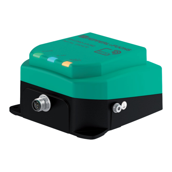
IUH-F190-V1-*, IUT-F190-R4-V1* Product Description Indicators and Operating Elements The read/write head has 3 LEDs, which are green/blue/yellow. The various indicators denote: Green LED: Power on Blue LED: Transmission mode Yellow LED: Read/write operation successful Connection IUH-F190-V1-* The IUH-F190-V1-* read/write head is connected to the IDENTControl control interface via the M12 x 1 connector. -
Page 25: Scope Of Delivery
Tighten the retaining bolt to a tightening torque of 1.6 Nm ± 0.4 Nm. Scope of Delivery Read/write head Quick start guide Accessories 3.8.1 IDENTControl The IUH-F190-V1-* read/write head can be connected to Pepperl+Fuchs IDENTControl control interfaces. Interface Designation 4 read/write heads: Ethernet IC-KP-B17-AIDA1... -
Page 26: Read/Write Tags
IUH-F190-V1-*, IUT-F190-R4-V1* Product Description 3.8.2 Read/Write Tags Type Designation EPC Gen 2 (ISO/IEC 18000-63) IUC72-F152-M-FR1 IUC72-F152-M-FR2 IUC76-50-FR1 IUC76-50-FR2 IUC76-F157-M-FR1 IUC76-F157-M-FR2 IUC76-F203-M-FR1 IUC76-F203-M-FR2 IUC76-C8-T14-GBL IUC77-F151-M-GBL IUC77-25L100-GBL IUC77-25L110-GBL Table 3.2 3.8.3 Connection cable for R/W heads and trigger sensors Compatible connection cables with shielding are available for connecting the R/W heads and trigger sensors. -
Page 27: Cable Connectors For The Power Supply
IUH-F190-V1-*, IUT-F190-R4-V1* Product Description 3.8.4 Cable connectors for the power supply Compatible M12 sockets with an open cable end for connecting the IDENTControl to a power supply are available in different lengths. Figure 3.7 Accessories Designation Length 2 m (straight socket) V1-G-2M-PUR Length 5 m (straight socket) V1-G-5M-PUR... -
Page 28: Installation
Mounting the read/write head Make sure that the read/write head is firmly attached to the mounting surface. Note! The installation recommendations made in this document are based on favorable conditions. Pepperl+Fuchs GmbH provides no guarantee of correct function in cross environments. -
Page 29: Room Orientation
IUH-F190-V1-*, IUT-F190-R4-V1* Installation Mounting the read/write head Figure 4.1 4.3.1 Room Orientation The alignment of the read/write tag antennae in relation to the antennae of the read/write head influences the detection range of the system. Make sure the antennae are aligned parallel to each other. -
Page 30: Minimum Distances
IUH-F190-V1-*, IUT-F190-R4-V1* Installation 4.3.2 Minimum Distances When positioning the read/write head, please observe the minimum distances. The lateral distance between the read/write head and metals or liquids should be at least 50 cm. The distance between the read/write head and the ground should be at least 50 cm. metal support Figure 4.2 During simultaneous operation of several read/write heads, only one read/write head may ever... -
Page 31: Connection
IUH-F190-V1-*, IUT-F190-R4-V1* Installation The integrated antenna of the read/write head has dual linear polarization. The read/write head operates in combined mode by default. In combined mode, both horizontal and vertical polarization are used for each read/write access. This increases the reading reliability of tags with an unknown location in the room. -
Page 32: Emc Concept
IUH-F190-V1-*, IUT-F190-R4-V1* Installation EMC Concept The outstanding noise immunity of the IDENTControl against emission and immission is based on its consistent shielding design, which uses the principle of the Faraday cage. Interference is caught in the shield and safely diverted via the ground connections. write head IDENTControl Control... -
Page 33: Commissioning
IUH-F190-V1-*, IUT-F190-R4-V1* Commissioning Commissioning Definitions 5.1.1 Display Angle brackets contain the abbreviated meaning of a command structure, e.g., <Data> The index or .xx denotes a hexadecimal number. denotes a value in the hexadecimal system, specified in ASCII characters. ASCII Example: 10 corresponds to A corresponds to 41 . -
Page 34: Sensor Settings
IUH-F190-V1-*, IUT-F190-R4-V1* Commissioning <WordAddr>: Word start address in the read/write tag, 4 hex characters, range ASCII from "0000h" to "FFFF", depending on tag type <WordNum>: Number of words to be read or written, 2 hex characters. Range ASCII from "01" through "20" depending on the tag type, word lengths are 4 bytes Sensor Settings Warning! - Page 35 IUH-F190-V1-*, IUT-F190-R4-V1* Commissioning Move a tag into the read/write head's detection range. When the tag has been detected and the read-only code has been read out, the "READ / WRITE" LED on the read/write head lights up yellow. The read-only code is displayed in the terminal program. Serial Ethernet PROFIBUS/PROFINET...
- Page 36 IUH-F190-V1-*, IUT-F190-R4-V1* Commissioning Parameterizing the Read/Write Head Requesting and Setting the Transmission Power Read out the read/write head's transmission power with the read parameter PT command: Serial Ethernet PROFIBUS/PROFINET Command: RP1UPT.00.00 .00.0A.BE.03.00.55.50.54. .BE.03.00.55.50.54.00.00 00.00 Confirmation: .00.06.BE.03.FF.33 .BE.03.FF.33 Response: .30.31.00.32 .00.0A.BE.03.00.34.00.02. .BE.03.00.34.00.02.00.32 00.32 The read/write head's set transmission power is 50 mW (32...
-
Page 37: Operation
IUH-F190-V1-*, IUT-F190-R4-V1* Operation Operation General The sections below contain information about the commands that relate to your read/write head. The commands are described using the example of an IDENTControl control interface with serial interface. All other generally applicable commands and error messages or status messages can be found in the manual for your IDENTControl control interface. -
Page 38: Command Overview
IUH-F190-V1-*, IUT-F190-R4-V1* Operation The reflections and the resulting spatial inhomogeneity of the field strength depend on the frequency used. The absolute value of the field strength depends on the transmission power. Since the tags move in the measurement range of the read/write head, and the environment can change, it is advisable to repeat the commands at different transmission frequencies and at varying power. -
Page 39: Read/Write Commands
IUH-F190-V1-*, IUT-F190-R4-V1* Operation Abbreviation Command description EW, #EW See "Enhanced Write Words EW" on page 43 See "Kill UHF Tag KI" on page 43 Filter Commands Abbreviation Command description See "Set Filter Mask FI" on page 44 See "Activate/Deactivate Filter MF" on page 45 Configuration Commands Abbreviation Command description See "Read Parameters"... - Page 40 IUH-F190-V1-*, IUT-F190-R4-V1* Operation Single Read Special Read-Only Code SS This command reads the UII segment from tags according to EPC Gen2 (ISO/IEC 18000-63). Command: SS <ChanNo> 0 <CHCK> <ETX> Response: <Status> <ChanNo> <Length> <SpecialFixcode> <CHCK> <ETX> F <ChanNo> 0001 <CHCK> <ETX> Example: SS10 reads the entire UII segment.
- Page 41 IUH-F190-V1-*, IUT-F190-R4-V1* Operation Single Write Special Read-Only Code SP This command writes a <Length> octet long UII/EPC code to tags according to EPC Gen 2 (ISO/IEC 18000-63). Command: SP <ChanNo> <Length> <SpecialFixcode> <CHCK> <ETX> Response: <Status> <ChanNo> <NUL> <Length> <SpecialFixcode> <CHCK> <ETX> F <ChanNo>...
- Page 42 IUH-F190-V1-*, IUT-F190-R4-V1* Operation Single Read Words SR One attempt is made to read <WordNum> 32-bit words from address <WordAddr>. Command: SR <ChanNo> <WordAddr> <WordNum> <CHCK> <ETX> Response: <Status><ChanNo><Luii><UII><Ldata><Data ><CHCK> <ETX> F <ChanNo> 0001<CHCK> <ETX> Example: SR1000101 reads a 4-byte word from memory address "0001." Note! The memory bank (MB) parameter defines the bank accessed by this command.
- Page 43 IUH-F190-V1-*, IUT-F190-R4-V1* Operation Note! When writing to the UII/EPC area (MB = 1), note that it is not possible to write to the CRC. The first writable address is 0x0001. The protocol control word <PC> begins at this address. Use the command #SW.
-
Page 44: Filter Commands
IUH-F190-V1-*, IUT-F190-R4-V1* Operation Example: KI10018.E2.00.90abcd.00 kills a UHF tag with a UII starting ".E2.00.90" and using the password "abcd." Filter Commands Each read or write command can access one, several, or all tags in a measurement range. The process is controlled by filter masks, which are managed via the commands Set Filter Mask (FI) and Activate/Deactivate Filter (MF). - Page 45 IUH-F190-V1-*, IUT-F190-R4-V1* Operation <MaskLength> Mask length, 28 = 40 , i.e., 40 bits 34.00.E2.00.90 <MaskData> Actual Mask Owing to the structure of the memory bank for UII/EPC ( see image on page 12), the start address is located at bit 16. The CRC-16 value occupies the memory position from bit 0 through bit 15;...
- Page 46 IUH-F190-V1-*, IUT-F190-R4-V1* Operation Command MF - Mode 1 In total, there are 15 tags in the measurement range of the read/write head, with three groups of five marked as either A, B, or C. The filter is now set to "B" by the command FI. If you execute command MF11 (Activate Filter - Mode 1), this command affects all subsequent commands.
-
Page 47: Configuration Commands
IUH-F190-V1-*, IUT-F190-R4-V1* Operation When the filter is set to "B," command MF12 (Filter Activated - Mode 2) selects all "A" and "C" tags, and the following commands address the unselected "B" tags. Read/write head Tags "A", "B", "C" Filter mask inverted Selected flag Difference Between Command MF - Mode 1 and Command MF - Mode 2 In both cases, the subsequent commands are applied only to the "B"... -
Page 48: Read And Write Parameters
IUH-F190-V1-*, IUT-F190-R4-V1* Operation 6.6.1 Read and Write Parameters With the read parameter (RP) and write parameter (WP) configuration commands, you can read/write the following parameters: Abbreviation Page Parameter is readable/writeable See "Antenna Polarization AP" on Readable/writeable page 49 See "CD Transmission Channels" on Readable/writeable for RC = 1, 4, 5, 6, page 50 Readable for RC = 2, 3, 7, 9, 10, 11,... -
Page 49: Parameters
IUH-F190-V1-*, IUT-F190-R4-V1* Operation Read Parameters The RP command reads configuration parameters from the read/write head. Command: RP <ChanNo> <SystemCode> <ParamTyp> <DataLength> <Data> <CHCK> <ETX> Response: <Status> <ChanNo> <Data> <CHCK> <ETX> <SystemCode> = U for IUH-* ASCII <ParamTyp> = 2 bytes ASCII <DataLength>... - Page 50 IUH-F190-V1-*, IUT-F190-R4-V1* Operation Set the polarization according to the read/write tag used (see chapter 4.3.3). You can achieve a better detection range if the polarization of the read/write head corresponds to the polarization of the read/write tag. Set the polarization to combined mode if the orientation of the tag is not known. In combined mode, first horizontal polarization and then vertical polarization is used for each read/write attempt.
- Page 51 IUH-F190-V1-*, IUT-F190-R4-V1* Operation Status 5 messages in the event of unstable tag reading. Read Out Filter Mask "Filter List" FL Parameter FL contains the current configuration of the filter masks as set during execution of command FI. The output format corresponds to the data input format of command FI without the filter number.
- Page 52 IUH-F190-V1-*, IUT-F190-R4-V1* Operation Memory Module for Tag Accesses to the "Memory Bank" MB This parameter specifies the bank accessed by the read/write commands SR, ER, SW, and EW. See chapter 3.2.3. ParamTyp: Default: MB = .03 = User Memory Value range: .00 = reserved (password area) .01 = UII/EPC .02 = TID...
- Page 53 IUH-F190-V1-*, IUT-F190-R4-V1* Operation If the country identifier RC = 01 (= 4 channels), RP1UMF.00.00 returns the response 01.63.64.67.65 Explanation of the response: <Status> = 0 <ChanNo> = 1 <PCh04> = .63 = 99 results in 99 - 100 = -1 dBm <PCh07>...
- Page 54 IUH-F190-V1-*, IUT-F190-R4-V1* Operation Transmission Power "Power Transmit" PT This parameter sets the transmission power in mW or reads out the transmission power set. ParamTyp: Default: Depending on the country-specific settings, see chapter 3.3. Value range: Depending on the country-specific settings, see chapter 3.3.
- Page 55 Parameter QV toggles the output protocol between single frame and multiframe. In single-frame protocol, the output corresponds to the Pepperl+Fuchs standard in LF and HF systems. If there is more than one tag in the measurement range, status A is output as a warning.
- Page 56 IUH-F190-V1-*, IUT-F190-R4-V1* Operation Responses Depending on Protocol Mode QV Parameter QV Single-frame protocol Multiframe protocol Command Responses No tag: No tag: 5<ChanNo> F<ChanNo>0000 One tag: Two tags: 0<ChanNo><UII> 0<ChanNo><Luii><UII1> Two tags: 0<ChanNo><Luii><UII2> A<ChanNo> F<ChanNo>0002 SR, #SR No tag: No tag: 5<ChanNo>...
- Page 57 IUH-F190-V1-*, IUT-F190-R4-V1* Operation Q Value QW In accordance with EPC Gen 2 (ISO/IEC 18000-63), the slotted ALOHA principle is used for anticollision. The number of time slots is defined as 2 . The parameter QW defines the Q value. As a guide, the number of time slots should roughly correspond to the number of expected tags in the measurement range.
- Page 58 IUH-F190-V1-*, IUT-F190-R4-V1* Operation Country Identifiers for IUH-F190-V1-FR2* and IUT-F190-R4-V1-FR2* Country Occupied Frequency Bandwidth Identifier Frequency Access Method Country or Region 902 MHz – 928 MHz Frequency hopping spread spectrum Canada Mexico Argentina Colombia 920 MHz – 925 MHz China Frequency hopping spread spectrum 915 MHz –...
- Page 59 IUH-F190-V1-*, IUT-F190-R4-V1* Operation Abbreviation Parameter Default value Number of Channels Depending on the country-specific settings, see chapter 3.3 Search Algorithm Off (255) Cancellation Criteria Power Transmit Depending on the country-specific settings, see chapter 3.3 Protocol Mode QV Multiframe Protocol (M) Q Value Country Identifier, "Region Not applicable...
-
Page 60: Read/Write Head With Integrated Rs-485 Interface
IUH-F190-V1-*, IUT-F190-R4-V1* Operation WP1UTA.00.01.03 permits 3 attempts RP1UTA.00.00 outputs the permitted number of attempts If the permitted number of write or read attempts between the read/write head and the tag is increased, this results in: More reliable reading and writing. Increased response time. -
Page 61: Multi-Drop Mode
IUH-F190-V1-*, IUT-F190-R4-V1* Operation System Commands Configure Interface CI This command configures the timeout and the baud rate. The values are stored in the nonvolatile memory. Any modifications become active only after a reset has been performed. The timeout is the time after which the read/write head no longer waits for characters in a command. - Page 62 IUH-F190-V1-*, IUT-F190-R4-V1* Operation Example! Command: <CommandCode> <DeviceNo> <CommandParameters> <CHCK> <ETX> Response: <Status> <DeviceNo> <Data> <CHCK> <ETX> You also have the option of replacing <CHCK><ETX> with #<CR>. A new command can be sent only after a response to the previous command has been received.
-
Page 63: Error/Status Messages
IUH-F190-V1-*, IUT-F190-R4-V1* Operation Configuration Commands See chapter 6.6 and see chapter 6.5 The device address must be specified. Read/Write Commands See chapter 6.4. Examples: Single Read Words SR The read/write head makes one attempt to read <WordNum> 32-bit words from the address <WordAddr>. - Page 64 IUH-F190-V1-*, IUT-F190-R4-V1* Operation Status Description Singleframe protocol: there are multiple tags in the measurement range (IUH*). Multiframe protocol: There are multiple tags in the measurement range that have the same UII/EPC (IUH*). Indicates the output of additional information (see "Output Additional Information, "Information"...
-
Page 65: Service And Maintenance
IUH-F190-V1-*, IUT-F190-R4-V1* Service and Maintenance Service and Maintenance The device is designed and constructed to function stable over long periods of time. For this reason, regular cleaning or maintenance is unnecessary. -
Page 66: Troubleshooting
IUH-F190-V1-*, IUT-F190-R4-V1* Troubleshooting Troubleshooting Problem Solution Interference from Use the multi-plex mode of the IDENTControl control interface several read/write Change the setting of the transmission channels heads in the direct vicinity Reduce the transmission power Status A message Check whether there are multiple tags in the detection range: Remove the tag from the detection range by placing the tag e.g. -
Page 67: Appendix
IUH-F190-V1-*, IUT-F190-R4-V1* Appendix Appendix Dimensions IUH-F190-V1-* and IUT-F190-R4-V1-* ø4 (3x) Figure 9.1 ASCII Table ASCII ASCII ASCII hex ASCII Space " &... -
Page 68: Detection Range
IUH-F190-V1-*, IUT-F190-R4-V1* Appendix ASCII ASCII ASCII hex ASCII < > Detection Range The read/write head has a typical detection range of around 1 meter; this range is determined by the tag used and can be adjusted by selecting the transmission power. Other influencing factors include the setup and installation of the specific application, interference from any materials present (in particular metal), and the ambient conditions. - Page 69 IUH-F190-V1-*, IUT-F190-R4-V1* Appendix Antenna Diagram The antenna diagrams show the electric field strength in the far field depending on the direction. The front of the read/write head points towards 0°. IUH-F190-V1-FR2* and IUT-F190-R4-V1-FR2* Horizontal Cut -180 0 dB -150 -3 dB -6 dB -9 dB -12 dB...
- Page 70 IUH-F190-V1-*, IUT-F190-R4-V1* Appendix Vertical Cut -180 0 dB -150 -3 dB -6 dB -9 dB -12 dB -120 -15 dB -18 dB -21 dB -24 dB -27 dB -30 dB 1.Read/write head points towards 0° Figure 9.3 - Horizontal polarization - Vertical polarization - Full width at half maximum...
- Page 71 IUH-F190-V1-*, IUT-F190-R4-V1* Appendix...
- Page 72 Twinsburg, Ohio 44087 · USA Tel. +1 330 4253555 E-mail: sales@us.pepperl-fuchs.com Asia Pacific Headquarters Pepperl+Fuchs Pte Ltd. Company Registration No. 199003130E Singapore 139942 Tel. +65 67799091 E-mail: sales@sg.pepperl-fuchs.com www.pepperl-fuchs.com Subject to modifications / DOCT-2945K Copyright PEPPERL+FUCHS • Printed in Germany 12/2017...
Need help?
Do you have a question about the IUT-F190-R4-V1 Series and is the answer not in the manual?
Questions and answers