
Related Manuals for Pepperl+Fuchs IO-Link ICE11-8IOL-G60L-V1D


Summary of Contents for Pepperl+Fuchs IO-Link ICE11-8IOL-G60L-V1D
- Page 1 ICE11-8IOL-G60L-V1D Fieldbus Module with Multiprotocol Technology and IO-Link CC-Link EtherCAT EtherNet/IP Modbus PROFINET Manual...
- Page 2 Phone: +49 621 776 - 0 E-mail: info@de.pepperl-fuchs.com North American Headquarters Pepperl+Fuchs Inc. 1600 Enterprise Parkway Twinsburg, Ohio 44087 Phone: +1 330 425-3555 E-mail: sales@us.pepperl-fuchs.com Asia Headquarters Pepperl+Fuchs Pte. Ltd. P+F Building 18 Ayer Rajah Crescent Singapore 139942 Phone: +65 6779-9091 E-mail: sales@sg.pepperl-fuchs.com https://www.pepperl-fuchs.com...
- Page 3 ICE11-8IOL-G60L-V1D Contents Introduction........................ 6 Content of this Document ................6 Manufacturer ....................6 Target Group, Personnel ................6 Symbols Used ....................7 Cybersecurity Information..................8 Product Description ....................10 Use and Application ..................10 Indicators and Operating Elements ............12 Interfaces and Connections ...............
- Page 4 ICE11-8IOL-G60L-V1D Contents Commissioning for EtherNet/IP................72 Configuration....................72 Configuration Parameters ................74 Process Data Assignment................86 Configuration and Operation with Rockwell Automation Studio 5000® ..........96 CIP Object Classes ..................107 8.5.1 EtherNet/IP Object Classes .................... 107 8.5.2 Manufacturer-Specific Object Classes................117 8.5.3 "Message" Configuration in Rockwell Automation Studio 5000® ........124 Commissioning with Modbus ................126 Preparation ....................126 Configuration....................127...
- Page 5 ICE11-8IOL-G60L-V1D Contents Troubleshooting..................... 231 13.1 Diagnostics Indicator in the Integrated Web Server ......231 13.2 Diagnostic Processing via CC-Link ............231 13.3 Alarm Signals and Error Messages from Modules via EtherCAT ..234 13.4 Diagnostic Processing via EtherNet/IP ........... 236 13.5 Diagnostic Processing via Modbus ............
- Page 6 Instruction manual • Functional safety manual • Other documents Manufacturer Pepperl+Fuchs Group Lilienthalstraße 200, 68307 Mannheim, Germany Internet: www.pepperl-fuchs.com Target Group, Personnel Responsibility for planning, assembly, commissioning, operation, maintenance, and dismount- ing lies with the plant operator. Only appropriately trained and qualified personnel may carry out mounting, installation, com- missioning, operation, maintenance, and dismounting of the product.
- Page 7 ICE11-8IOL-G60L-V1D Introduction Symbols Used This document contains symbols for the identification of warning messages and of informative messages. Warning Messages You will find warning messages, whenever dangers may arise from your actions. It is mandatory that you observe these warning messages for your personal safety and in order to avoid prop- erty damage.
- Page 8 ICE11-8IOL-G60L-V1D Cybersecurity Information Cybersecurity Information The ICE11-8IOL-G60L-V1D is secure for the area of application defined here in accordance with IEC 62443-4-1. The operator must implement the measures defined in this section to ensure the secure operation and protection of the device while online. Security Context The ICE11-8IOL-G60L-V1D is intended for use in an automation network.
- Page 9 ICE11-8IOL-G60L-V1D Cybersecurity Information The Following Measures Must Be Implemented on the Device for Commissioning: • Hardening: Change the device-specific password printed on the device. Access control with single factor authentication (SFA) • Special security Automatic login lock if access data is entered incorrectly after the sev- functions: enth attempt for a duration of 1 minute to protect against brute-force attacks.
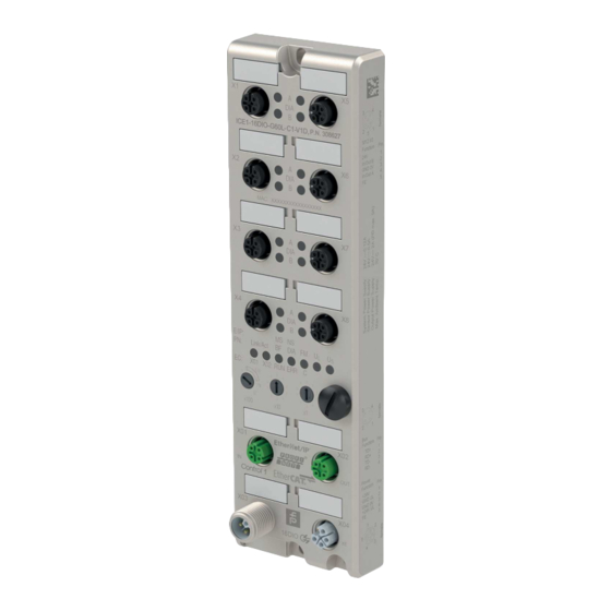
- Page 10 ICE11-8IOL-G60L-V1D Product Description Product Description Use and Application The module is a multiprotocol fieldbus module with 8 type A IO-Link master ports according to IO-Link standard V1.1.3. The G60L design in fully cast metal housing is resistant to mechanical damage and environ- mental influences.
- Page 11 ICE11-8IOL-G60L-V1D Product Description • This function makes it possible for you to easily replace the IO-Link device or the IO-Link master. This is possible from IO-Link specification V1.1 onward and only if the IO-Link device and the IO-Link master support the function. IO-Link device parameterization •...
- Page 12 ICE11-8IOL-G60L-V1D Product Description Indicators and Operating Elements Link/Act E/IP x100 Channel indicator LED Status indicator LED Rotary switch Note The LEDs in the lower area of the Ethernet IO module have different names and functions depending on the selected protocol. The following LED descriptions are therefore divided into a general part (1), which is valid for all protocol settings, and LED descriptions for a specific protocol setting (2).
- Page 13 ICE11-8IOL-G60L-V1D Product Description Indicators - General Part Description for LED A, B, DIA, U Function Green: Auxiliary sensor/actuator voltage OK • 18 V (± 1 V) < U < 30 V (± 1 V) : Auxiliary sensor/actuator voltage too low or too high •...
- Page 14 ICE11-8IOL-G60L-V1D Product Description EtherNet/IP Indicators E/IP area: relevant LEDs Lnk/Act X01, Lnk/Act X02, MS, NS Function Red: No configuration, slow or no physical connection Red flashing: Link exists but no communication link to the Ethernet/IP controller is available Off: No error Red: Ethernet/IP diagnostic alarm active Red flashing (1 Hz): Time-out or FailSafe mode is active Red flashing (2 Hz) for 3 s: DCP signal service is triggered via the bus...
- Page 15 ICE11-8IOL-G60L-V1D Product Description EtherCAT Indicators EC area: relevant LEDs Lnk/Act X01, Lnk/Act X02, BF, DIA Function Red: No configuration, slow or no physical connection Red flashing: Link exists but no communication link to the EtherCAT controller is available Off: EtherCAT control has established an active connection to the deviceNo error Red: Ethernet/IP diagnostic alarm active Red flashing (1 Hz): Time-out or FailSafe mode is active...
- Page 16 ICE11-8IOL-G60L-V1D Product Description Modbus Indicators MB area: relevant LEDs BF, DIA Function Red: Bus fault, no configuration, no or slow phys. connection Red flashing (2 Hz): Link present, but no communication connection to the Modbus-TCP controller Off: Modbus-TCP control has established an active connection to the device Red: Ethernet/IP diagnostic alarm active Red flashing (1 Hz): Time-out or FailSafe mode is active...
- Page 17 ICE11-8IOL-G60L-V1D Product Description Operating Elements Switch Function Rotary switch X100 Setting the fieldbus protocol Setting the IP address Rotary switch X10 Setting the IP address Rotary switch X1 Setting the IP address 1. Only EtherNET/IP Interfaces and Connections The contact arrangements below show the front view of the plug-in area of the connectors. Fieldbus Connection X01, X02 Caution! Risk of destruction!
- Page 18 ICE11-8IOL-G60L-V1D Product Description Connection for IO-Link, Digital Inputs/Outputs X1 ... X8 • Connection: M12 socket, 5-pin, A-coded • Color coding: black Caution! Risk of destruction with external sensor supply! The module infeed for the sensor supply U may only be provided over the specified power connection (Power X03/X04 >>...
- Page 19 ICE11-8IOL-G60L-V1D Product Description Note Power supply connection When connecting the power supply, ensure a separate power supply to the sensor and system via U and auxiliary voltage via U for actuators, for example. Where the plant has a separate power supply concept for system current and load current, this means the sensor and system area of the Ethernet IO module can continue working even if there is a failure of the load power supply.
- Page 20 ICE11-8IOL-G60L-V1D Product Description Dimensions 16.5 M12 x1 (10x) 11.5 190.3 191.8 Figure 3.6...
- Page 21 ICE11-8IOL-G60L-V1D Installation Installation General Information Install the module with two M6x25/30 size screws on a level surface. The required torque is 1 Nm. Use washers according to DIN 125. For the installation holes, use a spacing of 237.3 mm to 239.7 mm. Note Power supply connection When connecting the power supply, ensure a separate power supply to the sensor and system...
- Page 22 ICE11-8IOL-G60L-V1D Installation Warning! Risk of injury Terminals, the housing of field-wired terminal boxes or components may exceed a temperature of 60 °C. Warning! Use temperature-resistant cables with the following properties: Heat resistant up to at least 96 °C.
- Page 23 ICE11-8IOL-G60L-V1D Commissioning, Protocol Setting Commissioning, Protocol Setting MAC Addresses Each device has 3 unique, manufacturer-assigned MAC addresses that cannot be changed by the user. The first assigned MAC address is printed on the device. This MAC address has no function for EtherCAT®. For EoE (Ethernet over EtherCAT®), the device is assigned a virtual MAC address.
- Page 24 ICE11-8IOL-G60L-V1D Commissioning, Protocol Setting Figure 5.2 Select a module from those found. If the desired module is not displayed in the list of available nodes on the network, you can change the device filter and refresh the list. If the device still does not appear, please check your firewall settings. Assign the selected PROFINET device name to the module.
- Page 25 ICE11-8IOL-G60L-V1D Commissioning, Protocol Setting IODD The IODD consists of a set of files that formally describe an IO-Link device. The IODD is cre- ated by the device manufacturer and is required for each IO-Link device. The device can use an IODD to facilitate IO-Link device configuration and make process data more readable to people.
- Page 26 ICE11-8IOL-G60L-V1D Commissioning, Protocol Setting Setting a Protocol Multiprotocol modules have a total of three rotary switches. Move the first rotary switch X100 to the relevant switch position to set the protocol. For the other rotary switches, set the last two digits of the IP address when using EtherNet/IP.
- Page 27 ICE11-8IOL-G60L-V1D Commissioning, Protocol Setting If you set the rotary coding switch to an invalid position, the device signals this with a flash code: the BF/MS/ERR LED flashes red three times. You can change the IP address depending on the protocol you choose. EtherNet/IP If you use EtherNet/IP as the protocol, use rotary switch X100 to set the value 100 as the last octet of the IP address for the module.
- Page 28 ICE11-8IOL-G60L-V1D Commissioning, Protocol Setting CC-Link IE Field Basic If you opt for CC-Link IE Field Basic as the protocol, set rotary switch X100 to the value CC. You can use the X10 and X1 rotary switches to specify the last 2 digits of the IP address. You can select values between 0 and 9.
- Page 29 When restoring the factory settings, ensure that the module is connected to the voltage supply and switched on for at least 10 seconds. If it has been on for fewer than 10 seconds, the oper- ating system may be destroyed. The module would then need to be sent to Pepperl+Fuchs for repair.
- Page 30 ICE11-8IOL-G60L-V1D Commissioning with CC-Link Commissioning with CC-Link Preparation CSP+ file A CSP+ file describes the device information of a CC-Link device and is required to configure the module in an engineering tool. You can find the CSP+ file on the product detail page on our website pepperl-fuchs.com.
- Page 31 ICE11-8IOL-G60L-V1D Commissioning with CC-Link General Settings Setting Description Default Suppress U Diag- Supply voltage error U fault report nosis Mode 0 = enabled 1 = disabled 2 = auto Suppress Actuator Actuator without U voltage fault report Diagnosis without U 0 = enabled 1 = disabled Suppress U...
- Page 32 ICE11-8IOL-G60L-V1D Commissioning with CC-Link External Configuration Lock Configuration parameters can be set via various alternative interfaces (e.g., web interface, REST, OPC UA, MQTT). An external configuration can only be made as long as no cyclic PLC connection is active. Each new PLC configuration overwrites the external configuration set- tings.
- Page 33 ICE11-8IOL-G60L-V1D Commissioning with CC-Link Setting Description Default Swap Length Produc- Swap Length, Producing data 0: DWORD 1: WORD Offset Producing Swap Offset, Producing data 0 to 30 bytes Swap Count Produc- Swap Count, Producing data 0 to 30 bytes Sensor Supply Dis- Sensor supply disabled abled 0: Sensor supplied with electrical voltage...
- Page 34 ICE11-8IOL-G60L-V1D Commissioning with CC-Link Setting Description Default Error LED Disable, Pin Disable pin 2 error LED 0: Enable LED on channel B 1: Disable LED on channel B Error LED Disable, Pin Disable pin 4 error LED 0: Enable LED on channel A 1: Disable LED on channel A Level LED Disable, Disable pin 2 Level LED...
- Page 35 ICE11-8IOL-G60L-V1D Commissioning with CC-Link Validation and Backup This parameter enables the user to set the behavior of the IO-Link ports in relation to the type compatibility and data storage mechanism of the connected IO-Link device. The prerequisite for using Validation and Backup is that you configure the port mode to "IO-Link Manual."...
- Page 36 ICE11-8IOL-G60L-V1D Commissioning with CC-Link Type-Compatible V1.1 Device with Restore (Download Master to Device) Type-compatible with regard to IO-Link specification V1.1, which includes the validation of ven- dor ID and device ID. Only "Restore" is activated. Please note the following information on restore conditions: •...
- Page 37 ICE11-8IOL-G60L-V1D Commissioning with CC-Link Device ID The device ID is required for the validation of the IO-Link device and can be configured with this parameter. The prerequisite for using the device ID is that you configure the port mode to "IO-Link Man- ual."...
- Page 38 ICE11-8IOL-G60L-V1D Commissioning with CC-Link Swapping Offset The Swapping Offset describes the starting point in the process data for use of the configured Swapping Length. Both parameters depend on the configured input and output data size. Swapping Count The Swapping Count describes the number of bytes swapped in the process data using the configured Swapping Length.
- Page 39 ICE11-8IOL-G60L-V1D Commissioning with CC-Link DO Restart Mode In the event of a short-circuit or overload on an output channel, a diagnosis is signaled and the output is switched to "off." If DO Restart Mode is deactivated, the output channel is not automatically switched on again. It can be switched on after a logical reset of the channel's process output data.
- Page 40 ICE11-8IOL-G60L-V1D Commissioning with CC-Link Process Data Assignment The module supports process data communication in both directions. In this context, "consum- ing data" is defined as the process output data that controls the physical outputs and IO-Link output data. In this context, "producing data" is defined as the process input data that contains the physical inputs, diagnoses and IO-Link input data with optional extended status and event data.
- Page 41 ICE11-8IOL-G60L-V1D Commissioning with CC-Link Port Register for DI Register for IO-Link Access RWr40 – RWr4F RWr50 – RWr5F RWr60 – RWr6F RWr70 – RWr7F Table 6.3 1. = single bit 2. = WORD 3. Read-only Configuration and Operation with GxWorks® The configuration and commissioning of the module described in this chapter refers to the GxWorks®...
- Page 42 ICE11-8IOL-G60L-V1D Commissioning with CC-Link Adjusting Network Parameters Open GxWorks® and create a new project. Select the series and type of PLC used. Figure 6.2 To open the Settings window, navigate to Project > Parameter > "the selected CPU module" > Module Parameter. Figure 6.3 The CC-Link IE Field Basic Master Station can be configured in the window that opens.
- Page 43 ICE11-8IOL-G60L-V1D Commissioning with CC-Link Under CC-Link IEF Basic settings > To Use or Not to Use CC-Link IEF Basic Setting, select "Use". • The Network Configuration Settings option allows you to configure the CC-Link IE Field Basic Master, the connected stations, a network, parameters, and much more. •...
- Page 44 ICE11-8IOL-G60L-V1D Commissioning with CC-Link Figure 6.6 In the following window, under Method selection, select "Parameter read" or "Parameter write", depending on which method you would like to configure for the module. For details on the different parameters, see chapter 6.2. Figure 6.7 After you have set the parameters, click on Communication Setting Reflection of Slave Station to apply the changes to the appropriate module.
- Page 45 ICE11-8IOL-G60L-V1D Commissioning for EtherCAT Commissioning for EtherCAT EtherCAT EtherCAT® is a registered trademark amd patented technology, licensed by Beckhoff Automa- tion GmbH, Germany. Preparation Downloading and Installing the ESI File An ESI file (EtherCAT Slave Information file) is required to configure a module in the controller. The ESI file supports all module variants.
- Page 46 ICE11-8IOL-G60L-V1D Commissioning for EtherCAT 7.3.1 Configuration Input Data PDO content Size Type Index [byte] Index Size Type Name Input 0x1A00 0x6000:01 UINT32 1 byte IO-Link input data etc. etc. etc. etc. 0x6000:32 UINT32 32 byte IO-Link input data 0x1A01 0x6010:01 UINT32 1 byte IO-Link input data etc.
- Page 47 ICE11-8IOL-G60L-V1D Commissioning for EtherCAT PDO content Size Type Index [byte] Index Size Type Name Input 0x1A80 8 0xF100:01 UINT32 IO-Link connector status 1 0xF100:02 UINT32 IO-Link connector status 2 0xF100:03 UINT32 IO-Link connector status 3 0xF100:04 UINT32 IO-Link connector status 4 0xF100:05 UINT32 IO-Link connector status 5...
- Page 48 ICE11-8IOL-G60L-V1D Commissioning for EtherCAT PDO content Size Type Index [byte] Index Size Type Name Output 0x1606 0x7060:01 UINT32 1. bytes of IO-Link output data etc. etc. etc. etc. 0x7060:32 UINT32 32. bytes of IO-Link output data 0x1607 0x7070:01 UINT32 1. bytes of IO-Link output data etc.
- Page 49 ICE11-8IOL-G60L-V1D Commissioning for EtherCAT Slot Description IOL_O_32byte IO-Link, 32 bytes as process data output IOL_I/O_1/1byte IO-Link • 1 byte as process data input • 1 byte as process data output IOL_I/O_2/2byte IO-Link • 2 bytes as process data input • 2 bytes as process data output IOL_I/O_2/4byte IO-Link...
- Page 50 ICE11-8IOL-G60L-V1D Commissioning for EtherCAT 7.3.2 Device Parameters The modules support different parameters. The parameters are sent to the module during com- missioning of the controller. The following parameters can be set: Extended Parameters SDO content Index Size [byte] Index Size Type Name/description 0x23n0:01...
- Page 51 ICE11-8IOL-G60L-V1D Commissioning for EtherCAT Fail-Safe Function The firmware on the module provides a fail-safe function for the outputs for interruptions or loss of communication. When configuring modules, you can define the status of the outputs after an interruption or a loss of communication. Substitute values SDO content Index...
- Page 52 ICE11-8IOL-G60L-V1D Commissioning for EtherCAT Digital outputs mode SDO content Index Size [byte] Index Size Type Name/description 0x2380 0x2380:01 UINT8 Port 1 Channel A 0 = Set Low 1 = Set High 2 = Hold Last Other = Reserved 0x2380:02 UINT8 Port 1 Channel B 0 = Set Low 1 = Set High...
- Page 53 ICE11-8IOL-G60L-V1D Commissioning for EtherCAT SDO content Index Size [byte] Index Size Type Name/description 0x2380:12 UINT8 Port 6 Channel B 0 = Set Low 1 = Set High 2 = Hold Last Other = Reserved 0x2380:13 UINT8 Port 7 Channel A 0 = Set Low 1 = Set High 2 = Hold Last...
- Page 54 ICE11-8IOL-G60L-V1D Commissioning for EtherCAT General device settings SDO content Index Size [byte] Index Size Type Name/description 0x2381 0x2381:01 BOOL Web interface locked 0 = false 1 = true 0x2381:02 BOOL Force mode locked 0 = false 1 = true 0x2381:03 BOOL All emergency messages dis- abled...
- Page 55 ICE11-8IOL-G60L-V1D Commissioning for EtherCAT SDO content Index Size [byte] Index Size Type Name/description 0x2382 0x2382:01 UINT8 Surveillance Timeout Port 1 Channel A 0x2382:02 UINT8 Surveillance Timeout Port 1 Channel B 0x2382:03 UINT8 Surveillance Timeout Port 2 Channel A 0x2382:04 UINT8 Surveillance Timeout Port 2 Channel B 0x2382:05...
- Page 56 ICE11-8IOL-G60L-V1D Commissioning for EtherCAT SDO content Index Size [byte] Index Size Type Name/description 0x2383 0x2383:01 UINT8 Digital I/O Mode Port 1 Chan- nel B 1 = Input 2 = Output Other = Reserved 0x2383:02 UINT8 Digital I/O Mode Port 2 Chan- nel B 1 = Input 2 = Output...
- Page 57 ICE11-8IOL-G60L-V1D Commissioning for EtherCAT SDO content Index Size [byte] Index Size Type Name/description 0x2384 0x2384:01 UINT8 Digital Input Logic Port 1 Channel A 0 = NO 1 = NC 0x2384:02 UINT8 Digital Input Logic Port 1 Channel B 0 = NO 1 = NC 0x2384:03 UINT8...
- Page 58 ICE11-8IOL-G60L-V1D Commissioning for EtherCAT SDO content Index Size [byte] Index Size Type Name/description 0x2384:15 UINT8 Digital Input Logic Port 8 Channel A 0 = NO 1 = NC 0x2384:16 UINT8 Digital Input Logic Port 8 Channel B 0 = NO 1 = NC Table 7.10 Digital Input Filters...
- Page 59 ICE11-8IOL-G60L-V1D Commissioning for EtherCAT Timeout Before Restart The device supports the configuration of a pre-reboot digital output timeout for channel A (pin 4) and channel B (pin 2) of the IO-Link port. SDO content Index Size [byte] Index Size Type Name/description 0x2386 0x2386:01...
- Page 60 ICE11-8IOL-G60L-V1D Commissioning for EtherCAT Additional IO-Link Port Settings SDO content Index Size [byte] Index Size Type Name/description 0x30n0:01 UINT8 Swap mode 0x30n0 0x30n0:02 UINT8 Swap length 0x30n0:03 UINT8 Swap offset 0x30n0:04 BOOL Sensor supply activated 0 = false 1 = true 0x30n0:05 BOOL Pin 2 LED activated...
- Page 61 ICE11-8IOL-G60L-V1D Commissioning for EtherCAT IO-Link Parameterization SDO content Index Size [byte] Index Size Type Name/description 0x40n0:01 UINT8 Control panel 0x40n0 0x00 = no action 0x02 = read 0x03 = write 0x40n0:02 UINT8 Status 0x00 = no activity 0x01 = active/occupied 0x02 = access 0x04 = error 0xFF = failure...
- Page 62 ICE11-8IOL-G60L-V1D Commissioning for EtherCAT SDO content Index Size [byte] Index Size Type Name/description 0x80n0:37 UINT8 Number and structure of the process output data "ProcessDataOut" = value in IO-Link format acc. to version 1.0 of the IO-Link specification Bit 0 ... 4 = length Bit 5 = reserved Bit 6 = SIO indicator.
- Page 63 ICE11-8IOL-G60L-V1D Commissioning for EtherCAT IO-Link Information Data SDO content Index Size [byte] Index Size Type Name/description 0x90n0:01 UINT32 Device ID 0x90n0 0x90n0:05 UINT32 Vendor ID 0x90n0:32 UINT8 IO-Link version Version of the IO-Link specification of the connected IO-Link device acc. to version 1.0 of the IO-Link specification.
- Page 64 ICE11-8IOL-G60L-V1D Commissioning for EtherCAT 1. n = number between 0 ... 7 = port number -1 IO-Link Serial Number of Connected Devices SDO content Index Size [byte] Index Size Type Name/description 0x90n1:01 VISI- Serial number 0x90n1 BLE_STRING Table 7.18 1. n = number between 0 ... 7 = port number -1 7.3.3 Configuration Example with TwinCAT®...
- Page 65 ICE11-8IOL-G60L-V1D Commissioning for EtherCAT Figure 7.1 If you have not already done so, select a network adapter and install the driver for EtherCAT® real-time communication. Navigate to Adapters in the right-hand window and click on Compatible Devices... to select the driver and start the installation. Figure 7.2...
- Page 66 ICE11-8IOL-G60L-V1D Commissioning for EtherCAT Configuration Navigate to Solution Explorer > I/O > Devices in the left-hand window. Right-click on Device 1 (EtherCAT) and select the Add New Item... option. Select the device and click on OK. Figure 7.3 Navigate to Slots in the right-hand window and configure the IO-Link channels. For example, you can change the input/output length, channel mode or I/O mode of channel B (pin 2).
- Page 67 ICE11-8IOL-G60L-V1D Commissioning for EtherCAT EoE IP Address Note An IP address must be set if the web server will be used for the module in the future. If web server services are not to be facilitated, you can also disable this option.
- Page 68 ICE11-8IOL-G60L-V1D Commissioning for EtherCAT Figure 7.6 Activating Configuration Danger! Risk of personal injury or material damage. Keep clear of moving machine parts while adjusting the settings on the inputs and outputs of the device. If the module is connected to the EtherCAT network, select TWINCAT in the menu bar and then Activate Configuration.
- Page 69 ICE11-8IOL-G60L-V1D Commissioning for EtherCAT Figure 7.7 Note Configuration of the PLC and module is now complete. You may now create your user program. Firmware Update A firmware update of the device is possible via the integrated web server using the EoE proto- , or the FoE protocol Danger! Risk of data loss, damage to the device and injury due to uncontrolled machine movements.
- Page 70 ICE11-8IOL-G60L-V1D Commissioning for EtherCAT Figure 7.8 In the device window on the right, go to the File Access over EtherCAT box and click on Download. In the following window, select the update file provided by Belden: Figure 7.9 In the "String:" Field, add the file extension ".fwu", if not already visible: Figure 7.10 Click on OK and wait for the file to be transferred to the device.
- Page 71 ICE11-8IOL-G60L-V1D Commissioning for EtherCAT Note After the file has been transferred, the device resets automatically. During the restart, older firmware update files are replaced by the files in the update package.
- Page 72 ICE11-8IOL-G60L-V1D Commissioning for EtherNet/IP Commissioning for EtherNet/IP Configuration The module supports implicit messaging and explicit messaging for EtherNet/IP communica- tion. I/O process data is transmitted cyclically; assembly object connections are transmitted via implicit messaging. Non-critical data with low priority, configuration settings and diagnostic data can be exchanged via acyclic messages using explicit messaging.
- Page 73 ICE11-8IOL-G60L-V1D Commissioning for EtherNet/IP IO-Link Parameters, Exclusive Owner Connection Properties Parameter Content Connection name IO-Link (Exclusive Owner) Application type Exclusive owner Trigger mode Cyclic min. 1 ms Table 8.3 Connection Parameters, O -> T Parameter Content Real time transfer format 32 Bit Run/Idle Header Connection type POINT2POINT...
-
Page 74: Table Of Contents
ICE11-8IOL-G60L-V1D Commissioning for EtherNet/IP Parameter Content Data type INT (2 bytes) Table 8.7 Connection Parameters, T -> O Parameter Content Real time transfer format Pure data and modeless Connection type MULTICAST Assembly ID Data size 0 ... 446 bytes Data type INT (2 bytes) Table 8.8 Configuration Parameters... -
Page 75: Table 8.9
ICE11-8IOL-G60L-V1D Commissioning for EtherNet/IP Byte Offset CIP Object Configuration Config Class 0xA0, Parameter Assembly Data Type Valid Values Instance 1 IO Mapping Mode SINT 0: Default Assign- Attribute 32 ment 1: Byte Swap 2: LSB Ch.A - MSB Ch.B 3: LSB Ch.B - MSB Ch.A 4: Free I/O Mapping Table 8.9... - Page 76 ICE11-8IOL-G60L-V1D Commissioning for EtherNet/IP IO Mapping Mode The module supports five different I/O mapping modes for Digital Output Channel Control and the Input Channel Status. Modes 0 to 3 are predefined bit mappings. Mode 4 is a free user- defined mapping that can be used in conjunction with the I/O mapping of channel 1 ... 16 in the channel settings.
- Page 77 ICE11-8IOL-G60L-V1D Commissioning for EtherNet/IP Channel Settings CIP Object Byte Offset Class 0xA0, Configuration Config Instance 1 ... Parameter Assembly Data Type Valid Values IO Mapping (Ch1 ... SINT[16] 0 ... 15: Bit number of Attribute 1 16 channel process data 16: Inactive DO Surveillance Tim- INT[16]...
- Page 78 ICE11-8IOL-G60L-V1D Commissioning for EtherNet/IP To use these parameters, it is necessary to configure the IO mapping mode of the general set- tings to Free IO Mapping (Mode 4). The default value for each parameter is its own channel number. DO Surveillance Timeout (Ch1 ... 16) The digital output channels are monitored during runtime.
- Page 79 ICE11-8IOL-G60L-V1D Commissioning for EtherNet/IP If a channel is set to "Normally Close", a high signal "0" is transmitted to the process input data, e.g., if an undamped sensor has a closed switching output. The channel LED indicates the physical input state of the port pin, regardless of these settings. DI Filter (Ch1 ...
- Page 80 ICE11-8IOL-G60L-V1D Commissioning for EtherNet/IP IO-Link Diagnostic Settings CIP Object Byte Offset Class Config 0xA2, Configuration Parameter Assembly Data Type Valid Values Instance 1 IO-Link master SINT 0: Disable Attribute 1 Diagnostics 1: Enable IO-Link-Device SINT 0: Disable Attribute 2 Error 1: Enable IO-Link-Device SINT...
- Page 81 ICE11-8IOL-G60L-V1D Commissioning for EtherNet/IP Settings IO-Link Port 1 ... 8 CIP Object Class Byte Offset 0xA3, Configuration Config Instance 1 ... Parameter Assembly Data Type Valid Values Output Data Size 224, 246, 268, SINT 0: No data Attribute 1 290, 1: 2 bytes 312, 334, 356, 2: 4 bytes...
- Page 82 ICE11-8IOL-G60L-V1D Commissioning for EtherNet/IP CIP Object Class Byte Offset 0xA3, Configuration Config Instance 1 ... Parameter Assembly Data Type Valid Values Validation and Backup 233, 255, 277, SINT 0: No device check Attribute 10 299, and clear, no data 321, 343, 365, storage 1: Type compatible, V1.0 device, no data...
- Page 83 ICE11-8IOL-G60L-V1D Commissioning for EtherNet/IP Output Data Size The output data size of the respective IO-Link device can be configured with this parameter. There can be up to 32 bytes of IO-Link output data per port. The output data size of each IO-Link device has an influence on the total output data size of the connection.
- Page 84 ICE11-8IOL-G60L-V1D Commissioning for EtherNet/IP Input Data Swapping Offset The Input Data Swapping Offset describes the starting point in the process data for use of the configured Input Data Swapping Mode. Both parameters depend on the configured input data size and the optional input data extension. IOL Failsafe The module supports a failsafe function for the output data of the IO-Link chan- nels.
- Page 85 ICE11-8IOL-G60L-V1D Commissioning for EtherNet/IP For more information, please refer to the 'IO-Link Interface and System Specification' version 1.1.3, which can be downloaded from https://io-link.com/. No Device Check, No Data Storage No verification of the connected manufacturer ID or device ID and no "backup and restore" sup- port of the IO-Link master parameter server.
- Page 86 ICE11-8IOL-G60L-V1D Commissioning for EtherNet/IP • Restore, Download / IOL Master to IOL Device A restore (download from the IOL master to the IOL device) is executed if an IO-Link device is connected and the IO-Link master has saved valid parameter data for the IOL device that does not correspond to the current device parameters.
- Page 87 ICE11-8IOL-G60L-V1D Commissioning for EtherNet/IP Digital Output - Channel Control Digital Output Channel Con- trol Bit 7 Bit 6 Bit 5 Bit 4 Bit 3 Bit 2 Bit 1 Bit 0 Channel num- Byte 0, ber, default mapping Byte 1, Table 8.20 The control values are effective if the corresponding channels are configured as outputs and Digital Output Control is set to DO Channel Control.
- Page 88 ICE11-8IOL-G60L-V1D Commissioning for EtherNet/IP Each status value is effective if the channel is configured as an input. General Diagnosis General Diag- nostics Bit 7 Bit 6 Bit 5 Bit 4 Bit 3 Bit 2 Bit 1 Bit 0 General Bit Byte 0, Byte 1, Table 8.24...
- Page 89 ICE11-8IOL-G60L-V1D Commissioning for EtherNet/IP 1 ... Actuator/U channel error on channel 1 ... 16 SIO-Link Diagnosis IO-Link Diagnos- tics Bit 7 Bit 6 Bit 5 Bit 4 Bit 3 Bit 2 Bit 1 Bit 0 General Bit Byte 0, ICE8 ICE7 ICE6 ICE5...
- Page 90 ICE11-8IOL-G60L-V1D Commissioning for EtherNet/IP Port Qualifier Information PQI Bit 7 Bit 6 Bit 5 Bit 4 Bit 3 Bit 2 Bit 1 Bit 0 General Bit Byte 0, DevErr DevCo PortAc- Subst- New- tive Byte 1, Table 8.29 NewPar Device parameter update detected SubstDev Substitute device, replacement device detected, different serial number PortActive...
-
Page 91: Instance
ICE11-8IOL-G60L-V1D Commissioning for EtherNet/IP Events IO-Link Events Bit 7 Bit 6 Bit 5 Bit 4 Bit 3 Bit 2 Bit 1 Bit 0 Event Qualifier Byte 0, Mode Type Instance Byte 1, Event Code 1 Byte 2 Event Code Byte 3 Event Qualifier Byte 4 Mode... - Page 92 ICE11-8IOL-G60L-V1D Commissioning for EtherNet/IP Connection parameters Data size output Data size input Default Output Process Data Byte-Offset Output Data Digital output channel control, 2 bytes Reserved, 2 bytes IO-Link port 1 data, control, 32 bytes IO-Link port 2 data, control, 32 bytes IO-Link port 3 data, control, 32 bytes IO-Link port 4 data, control, 32 bytes IO-Link port 5 data, control, 32 bytes...
- Page 93 ICE11-8IOL-G60L-V1D Commissioning for EtherNet/IP Byte-Offset Input Data IO-Link port 5 extended status, 8 bytes IO-Link port 5 events, 12 bytes IO-Link port 6 data, status, 32 bytes IO-Link port 6 PQI, 2 bytes IO-Link port 6 extended status, 8 bytes IO-Link port 6 events, 12 bytes IO-Link port 7 data, status, 32 bytes IO-Link port 7 PQI, 2 bytes...
- Page 94 ICE11-8IOL-G60L-V1D Commissioning for EtherNet/IP IO-Link Port 4 Data size output 8 bytes Data size input 2 bytes Data extension input No data IO-Link Port 5 ... 8 Data size output 0 byte Data size input 0 byte Data extension input No data Modified process data Byte- Offset...
- Page 95 ICE11-8IOL-G60L-V1D Commissioning for EtherNet/IP Byte- Offset Output Data Input Data IO-Link port 4 data, control, 8 bytes IO-Link port 4 data, status, 2 bytes IO-Link port 4 PQI, 2 bytes IO-Link port 5 PQI, 2 bytes IO-Link port 6 PQI, 2 bytes IO-Link port 7 PQI, 2 bytes IO-Link port 8 PQI, 2 bytes Table 8.34...
- Page 96 Select New Module from the menu. The following selection window opens: Figure 8.1 Use the Module Type Vendor Filter on the right-hand side to display all installed Pepperl+Fuchs devices. Select the device that you want to add and click on "Create."...
- Page 97 ICE11-8IOL-G60L-V1D Commissioning for EtherNet/IP Figure 8.2 Enter a name for the device and select the previously selected IP address. In this example, the name is ICE11 and the IP address is 192.168.1.1. Click on Change to change the settings for the device revision, the electronic coding and the connection type.
- Page 98 ICE11-8IOL-G60L-V1D Commissioning for EtherNet/IP Figure 8.4 Go to Controller-Tags in Controller Organizer. The controller tags for the configuration parameters contain the device name followed by a ":C." The configuration parameters can be set under Value. See chapter 8.2. Figure 8.5 The tag of the process data entered contains the device name followed by ":I.Data".
- Page 99 ICE11-8IOL-G60L-V1D Commissioning for EtherNet/IP Figure 8.6 When the configuration is complete, the parameters can be downloaded to the EtherNet/IP controller. Add-On Instruction AOI Rockwell Automation Studio 5000® provides the user with a mechanism for optimizing and encapsulating data and logic via an add-on instruction. This AOI can be added to a current path "rung"...
- Page 100 ICE11-8IOL-G60L-V1D Commissioning for EtherNet/IP Figure 8.7 Open the *.L5X file:...
- Page 101 ICE11-8IOL-G60L-V1D Commissioning for EtherNet/IP Figure 8.8 Click on OK to create the AOI with all the necessary User-Defined Data Types UDT: Figure 8.9...
- Page 102 ICE11-8IOL-G60L-V1D Commissioning for EtherNet/IP The imported components are displayed in the Controller Organizer: Figure 8.10 Check whether an error appears in the AOI tags as a red circle with a white cross. This can occur for the configuration data when you import an AOI into your system for the first time: Figure 8.11...
- Page 103 ICE11-8IOL-G60L-V1D Commissioning for EtherNet/IP If no error has occurred, go to step 9. Go to Edit Tags and adjust the data type to the module-defined type on your system: Figure 8.12 The Config data type must exactly match the data type associated with ConfigData. Because this data type is system-dependent, you may need to select it manually.
- Page 104 ICE11-8IOL-G60L-V1D Commissioning for EtherNet/IP Figure 8.14 To use the AOI, go to a logic, e.g., the MainRoutine. Add the IO-Link Master AOI to the current path "rung" via drag-and-drop: Figure 8.15 Right-click on the first element of the AOI and click on New Tag...:...
- Page 105 ICE11-8IOL-G60L-V1D Commissioning for EtherNet/IP Figure 8.16 Enter a name and click on Create to create an AOI: Figure 8.17 Assign the module's input, output and configuration data:...
- Page 106 ICE11-8IOL-G60L-V1D Commissioning for EtherNet/IP Figure 8.18 To create the tags for the remaining elements, repeat steps 10 and 11: Figure 8.19 Your logic no longer creates a copy of the input data and the output data simultaneously. It uses the new data tags as an interface for data exchange with the module:...
- Page 107 ICE11-8IOL-G60L-V1D Commissioning for EtherNet/IP Figure 8.20 CIP Object Classes 8.5.1 EtherNet/IP Object Classes According to the CIP specification, the module supports the following standard EtherNet/IP object classes: Object Class Object ID Instances Identity Object 0x01 0, 1 Message Router Object 0x02 0, only on class level Assembly Object...
- Page 108 ICE11-8IOL-G60L-V1D Commissioning for EtherNet/IP Identity Object 0x01 Supported services: • Get Attributes All 0x01 • Reset 0x05: • 0 = Reset Module, Warmstart • 1 = Reset to Factory Default • Get Attribute Single 0x0E Class Attribute, Instance 0 Attribute Name Access Data Type Description Revision...
- Page 109 ICE11-8IOL-G60L-V1D Commissioning for EtherNet/IP Attribute Name Access Data Type Description Status WORD Summary status of device: b0: Owned b1: Reserved "0" b2: Configured b3: Reserved "0" b4 ... 7: Extended Device Status 0 = Self-Testing or Unknown 1 = Firmware Update in Progress 2 = At least one faulted I/O con- nection 3 = No I/O connections estab-...
- Page 110 ICE11-8IOL-G60L-V1D Commissioning for EtherNet/IP Assembly Object 0x04 Supported services: • Get Attribute Single 0x0E • Set Attribute Single 0x10 Class Attribute, Instance 0 Attribute Name Access Data Type Description Revision UINT Revision of this object Max. Instance UINT Maximum instance number of an object currently created in this class level of the device Number of Instances...
- Page 111 ICE11-8IOL-G60L-V1D Commissioning for EtherNet/IP DLR Object 0x47 Supported services: • Get Attributes All 0x01 • Get Attribute Single 0x0E Class Attribute, Instance 0 Attribute Name Access Data Type Description Revision UINT Revision of this object Max. Instance UINT Maximum instance number of an object currently created in this class level of the device Maximum ID Number...
- Page 112 ICE11-8IOL-G60L-V1D Commissioning for EtherNet/IP QoS Object 0x48 Supported services: • Get Attribute Single 0x0E • Set Attribute Single 0x10 Class Attribute, Instance 0 Attribute Name Access Data Type Description Revision UINT Revision of this object Max. Instance UINT Maximum instance number of an object currently created in this class level of the device Maximum ID Number...
- Page 113 ICE11-8IOL-G60L-V1D Commissioning for EtherNet/IP TCP/IP Object 0xF5 Supported services: • Get Attributes All 0x01 • Get Attribute Single 0x0E • Set Attribute Single 0x10 Class Attribute, Instance 0 Attribute Name Access Data Type Description Revision UINT Revision of this object Max.
- Page 114 ICE11-8IOL-G60L-V1D Commissioning for EtherNet/IP Attribute Name Access Data Type Description Select Acd Get, Set BOOL Enables "1" or disables "0" the use of ACD, default value "1" Last Conflict Detected Get, Set STRUCT Structure containing information related to the last conflict detected Encapsulation Inactiv- Get, Set UINT...
- Page 115 ICE11-8IOL-G60L-V1D Commissioning for EtherNet/IP Attribute Name Access Data Type Description Interface Counters STRUCT Interface Counters Media Counters STRUCT Media-specific counters Interface Control Get, Set STRUCT Configuration for physical inter- face Control Bits, WORD: b0: Auto-negotiate b1: Forced Duplex Mode, 0 = Half Duplex;...
-
Page 116: Attribute
ICE11-8IOL-G60L-V1D Commissioning for EtherNet/IP LLDP Management Object 0x109 Supported services: • Get Attributes All 0x01 • Get Attribute Single 0x0E • Set Attribute Single 0x10 Class Attribute, Instance 0 Attribute Name Access Data Type Description Revision UINT Revision of this object Max. -
Page 117: Attribute
ICE11-8IOL-G60L-V1D Commissioning for EtherNet/IP Attribute Name Access Data Type Description LLDP Datastore WORD Indication of the retrieval methods for the LLDP database: b0: LLDP Data Table Object (0) b1: SNMP (1) b2: NETCONF YANG (0) b3: RESTCONF YANG (0) b4 ... b15: Reserved (0) Last Change UDINT Counter in seconds from the last... - Page 118 ICE11-8IOL-G60L-V1D Commissioning for EtherNet/IP Attribute Name Access Data Type Description Report U Sup- Get, Set BOOL 0: Disable 1: Enable ply Voltage Fault Report DO Fault with- Get, Set BOOL 0: Disable out U 1: Enable 7 ... 24 Reserved CIP object configura- Get, Set BOOL...
- Page 119 ICE11-8IOL-G60L-V1D Commissioning for EtherNet/IP Attribute Name Access Data Type Description DI Filter Get, Set SINT 0: Disabled 1: 1 ms 2: 2 ms 3: 3 ms 4: 6 ms 5: 10 ms 6: 15 ms 8 ... 9 Reserved Channel Mode Get, Set SINT 0: Inactive...
- Page 120 ICE11-8IOL-G60L-V1D Commissioning for EtherNet/IP IO-Link Port Settings Object 0xA3 Supported services: • Get Attribute Single 0x0E • Set Attribute Single 0x10 Class Attribute, Instance 0 Attribute Name Access Data Type Description Revision UINT Revision of this object Max. Instance UINT Maximum instance number of an object currently created in this class level of the device...
- Page 121 ICE11-8IOL-G60L-V1D Commissioning for EtherNet/IP Attribute Name Access Data Type Description Validation and Backup Get, Set SINT 0: No device check and clear, no data storage 1: Type compatible V1.0 device, no data storage 2: Type compatible V1.1 device, no data storage 3: Type compatible V1.1 device with Backup + Restore, Download + Upload...
- Page 122 ICE11-8IOL-G60L-V1D Commissioning for EtherNet/IP IO-Link Device Parameter Object 0xA5 Supported services: Instance 0 • Get Attribute Single 0x0E Instance 1 ... 8 • Get ISDU data 0x4B • Set ISDU data 0x4C Class Attribute, Instance 0 Attribute Name Access Data Type Description Revision UINT Revision of this object...
- Page 123 ICE11-8IOL-G60L-V1D Commissioning for EtherNet/IP Set ISDU Data The index, subindex and IO-Link data must be set in the source data. The data length of the request depends on the data type of the IO-Link device. The different protocol data formats between EtherNet/IP (Little-Endian) and IO-Link (Big-Endian) must be noted.
- Page 124 ICE11-8IOL-G60L-V1D Commissioning for EtherNet/IP 8.5.3 "Message" Configuration in Rockwell Automation Studio 5000® Attributes of CIP object classes can be edited in Rockwell Automation Studio 5000® using the Message instruction. This requires the selection of the correct message and service type with the corresponding service code.
- Page 125 ICE11-8IOL-G60L-V1D Commissioning for EtherNet/IP Get/Set ISDU Data The IO-Link device parameter object instance 1 ... n can be accessed with the manufacturer- specific Get/Set ISDU data service via the CIP object class ID, the instance ID and the attribute ID. The index and the subindex must be set in the source data. The IO-Link data must be appended for the Set ISDU data service.
- Page 126 ICE11-8IOL-G60L-V1D Commissioning with Modbus Commissioning with Modbus Preparation Device identification With each MODBUS client, the server can be reached to obtain identification data such as manufacturer name, product code, and revision. Register Length Description Default Access 401025 "Version major" device firm- –...
- Page 127 ICE11-8IOL-G60L-V1D Commissioning with Modbus Setting network parameters Use the two right-hand rotary switches X10 and X1 on the front of the device to set the last octet of the static IP address. Each rotary switch in the Modbus TCP area is assigned a decimal place, so that a number between 0 and 99 can be configured.
- Page 128 ICE11-8IOL-G60L-V1D Commissioning with Modbus Register Length Description Default Access 400597 Output auto restart 0 = Auto restart of outputs dis- abled 1 = Auto restart of outputs enabled 400598 Web interface lock 0 = Web interface lock dis- abled 1 = Web interface lock enabled 400599 Force mode lock...
- Page 129 ICE11-8IOL-G60L-V1D Commissioning with Modbus Configuration parameters can be set via various alternative interfaces. An external configura- tion can only be made as long as no cyclic PLC connection is active. Each new PLC configura- tion overwrites the external configuration settings. Channel Settings Register Length...
- Page 130 ICE11-8IOL-G60L-V1D Commissioning with Modbus Hold Last: If failsafe is active, the physical output pin of the channel maintains the last valid pro- cess data status. DO Restart Mode In the event of a short-circuit or overload on an output channel, a diagnosis is signaled and the output is switched to "off."...
- Page 131 ICE11-8IOL-G60L-V1D Commissioning with Modbus Register Length Description Default Access 402137 IO-Link Ch. 8 Serial no. Table 9.5 1. Read-only Detailed channel settings: The following example for channel 1 shows all possible port settings for IO-Link. The values are identical for all 8 ports. Register Length Description...
- Page 132 ICE11-8IOL-G60L-V1D Commissioning with Modbus Register Length Description Default Access 401522 Swapping offset, producing 0 to 30 bytes 401523 Swapping offset, consuming 0 to 30 bytes 401524 Pin2 LED activated 0: Inactive LED on channel B 1: Active LED on channel B 401525 Suppress all diagnoses 0: Create diagnoses on this...
- Page 133 ICE11-8IOL-G60L-V1D Commissioning with Modbus The IO-Link port is activated and no explicit port configuration is required. Configurations such as Validation and Backup, Vendor ID, Device ID, and Cycle Time are not required. Digital input: In this mode, the channel operates as a digital input. The status of the channel can be seen in the Digital Input Channel Status of the cyclical process data.
- Page 134 ICE11-8IOL-G60L-V1D Commissioning with Modbus • Parameters are written to an IOL device in single parameter mode: If single parame- ter data on the IOL device is changed during operation, the device parameters stored on the IOL master can be updated using the ParamDownloadStore com- mand.
- Page 135 ICE11-8IOL-G60L-V1D Commissioning with Modbus The cycle time can be set manually to the options provided. This option can be used, for exam- ple, for IO-Link devices that are connected via inductive couplers. Inductive couplers are usu- ally the bottleneck in the update cycle time between the IO-Link master and the IO-Link device. In this case, please refer to the datasheet of the inductive coupler.
- Page 136 ICE11-8IOL-G60L-V1D Commissioning with Modbus Replacement Value A substitute value can be set for each IO-Link device via the IO-Link failsafe parameter object. If failsafe is active, these substitute values are transmitted to the IO-Link device. The currently configured IO-Link output data size must be taken into account. Note that in the case of a fault, the substitute values are sent instead of the output process data, so a configured swapping mode has an influence on the byte order.
- Page 137 ICE11-8IOL-G60L-V1D Commissioning with Modbus Consuming data, output Register Length Description Default Access 400001 Output Port 1 process data 400017 Output Port 2 process data 400033 Output Port 3 process data 400049 Output Port 4 process data 400065 Output Port 5 process data 400081 Output Port 6 process data 400097...
- Page 138 ICE11-8IOL-G60L-V1D Commissioning with Modbus Example for producing data Port Mode Valid output data is written IO-Link 1 Byte Input Least significant 1 Byte of 400257 Digital Input Least significant Bit of 400273 IO-Link 4 Bytes Input Every 2 bytes on registers 400289 to 400290 IO-Link 16 Bytes Input Every 2 bytes on registers 400305 to 400312 IO-Link 32 Bytes Input...
- Page 139 To configure the modules in the control system, you need a GSD file in XML format. You can download this file from our website at https://www.pepperl-fuchs.com. The file for the PROFINET modules is named GSDML-V2.41-Pepperl+Fuchs-ICE11-yyyym- mdd. In this case, yyyymmdd is the issue date of the file.
- Page 140 ICE11-8IOL-G60L-V1D Commissioning for PROFINET 10.2.1 Integration of PROFINET IO Modules in the TIA Portal Install the GSDML file for the desired module in the TIA portal. Once the GSDML file for the PROFINET modules has been installed, the modules are avail- able in the TIA portal hardware catalog.
- Page 141 ICE11-8IOL-G60L-V1D Commissioning for PROFINET Figure 10.3 Assign the module to the PROFINET network. Figure 10.4 Switch to the device configuration. Select the desired device to view the configuration options. Figure 10.5 10.2.2 Assignment of a Device Name and IP Address Assignment of a unique device name and IP address PROFINET IO devices are addressed in the PROFINET network via a unique device name.
- Page 142 ICE11-8IOL-G60L-V1D Commissioning for PROFINET Figure 10.6 Verify that the controller and I/O device are on the same ETHERNET subnet. Either use or modify the device name and IP address defaults. For a correctly working setup, the selected device name must be programmed online in the I/O device.
- Page 143 ICE11-8IOL-G60L-V1D Commissioning for PROFINET 10.2.3 Configuring the IO-Link Channels By default, all channels are preconfigured as IO-Link I/O 32/32 bytes + PQI according to IO- Link specification V1.1.3. Presetting the Channels Figure 10.9 The IO-Link channels (C/Q or channel A/pin 4 of the I/O port) in sub-slots 2–9 (port X1 of the device corresponds to sub-slot 2, ..., port X8 of the device corresponds to sub-slot 9) can be configured flexibly.
- Page 144 ICE11-8IOL-G60L-V1D Commissioning for PROFINET Creating an IO-Link Channel Configuration The I/O Module Submodules folder in the hardware catalog displays all configurable options that can be selected. IO-Link Channel Configuration Figure 10.12...
- Page 145 ICE11-8IOL-G60L-V1D Commissioning for PROFINET Select the desired option and then click and hold the left mouse button to drag the configuration to a free IO-Link sub-slot. Figure 10.13 The following options are available for the IO-Link C/Q channel (channel A/pin 4): Digital Input: In this mode the channel works as a digital input.
- Page 146 ICE11-8IOL-G60L-V1D Commissioning for PROFINET 10.2.4 Parameterization of the Status/Control Module Status/Control Module Figure 10.14 Parameters in the status/control module: Figure 10.15 The status/control module in slot 1/sub-slot 1 is permanently preconfigured for each module. It contains 2 bytes of input data and 2 bytes of output data for the digital IO data plus status and control bits of the IO-Link master.
- Page 147 ICE11-8IOL-G60L-V1D Commissioning for PROFINET Danger! Unexpected signals, machine movements Risk of injury or death! Unsupervised forcing can lead to unexpected signals and uncontrolled machine movements. • External Configuration Configuration and parameter data can be set via various external interfaces outside the GSDML configuration, e.g., web interface, REST, OPC UA, MQTT.
- Page 148 ICE11-8IOL-G60L-V1D Commissioning for PROFINET Mode 1 Figure 10.18 Mode 2 Figure 10.19 Mode 3 Figure 10.20 Mode 4 Figure 10.21 Mode 5 Figure 10.22 For details on I/O mapping, see chapter 10.3.
- Page 149 ICE11-8IOL-G60L-V1D Commissioning for PROFINET General Diagnostic Settings Diagnostic Settings for Modules with IO-Link Class A Ports Figure 10.23 • Report U supply voltage fault alarms The U supply voltage fault alarm can be set to "Disabled" or "Enabled" with this param- eter.
- Page 150 ICE11-8IOL-G60L-V1D Commissioning for PROFINET Parameters of the IO-Link Channels Figure 10.25 Extended Port Parameters • Sensor Supply Mode Pin 1/L+ The sensor voltage at pin 1 is permanently active and cannot be deactivated. • DI Filter This parameter can be used to define the filter time of the digital input. The following options are available: Off;...
- Page 151 ICE11-8IOL-G60L-V1D Commissioning for PROFINET • Automatic Restart after Failure: If an output short-circuit or overload is detected, the output is switched off from the IO-Link master. However, after a time delay, the output is automatically switched on again to check whether the overload or short-circuit state is active. •...
- Page 152 ICE11-8IOL-G60L-V1D Commissioning for PROFINET • Swapping Offset: Swapping offset in bytes can be set depending on the configured I/O data length. If "2" is set, byte 3 is swapped. Default setting: 0 Failsafe Port Parameters for Ch. A in IO-Link Mode Figure 10.26 Selectable values, for output data only To ensure proper functioning of the IO-Link failsafe values, the IO-Link node parameters should...
- Page 153 ICE11-8IOL-G60L-V1D Commissioning for PROFINET Figure 10.28 Word data If the "Fail Safe Value(s)" option "Replacement Value" has been set, the replacement value entered in this input field(s) is used. The value must be entered as a decimal value. Depending on the configured data length, the values must be entered as bytes (0 –...
- Page 154 ICE11-8IOL-G60L-V1D Commissioning for PROFINET Input Fraction, Ch. A If the user configures a sub-slot module with less than the actual input data of the device, the IO-Link master sends as many IO-Link node input bytes as possible to the PLC, including the PQI byte of the sub-slot module.
- Page 155 ICE11-8IOL-G60L-V1D Commissioning for PROFINET Validation and Backup, Ch. A To use the validation and backup functionality of the IO-Link master, set the port mode to IO- Link - manual. Depending on the Validation and Backup setting, an entry in the Vendor ID and Device ID parameters is mandatory.
- Page 156 ICE11-8IOL-G60L-V1D Commissioning for PROFINET • Type-compatible (V1.1) IO-Link-Device with Restore: Type-compatible according to IO-Link specification V1.1, Vendor ID and Device ID are 2<Default ¬¹ Font> checked by the IO master with Restore IO-Link Device Parameter. 2<Default ¬¹ Font> Restore During the initial connection to an IO-Link node after activating this mode, the IO-Link master loads the IO-Link node parameters into the backup memory once For each additional connection to an IO-Link node, the IO-Link master compares the saved parameters with the IO-Link node parameters and loads the saved backup parame-...
- Page 157 ICE11-8IOL-G60L-V1D Commissioning for PROFINET Note An IO-Link device sets the upload flag independently if parameters have been written to the IO- Link device in block mode. 10.2.6 IO-Link Device Parameterization Siemens IO-Link Library You can use the SIEMENS "IO_LINK_DEVICE" function block (FB50001) to write or read out the data of an IO-Link node connected to the IO-Link master acyclically.
- Page 158 ICE11-8IOL-G60L-V1D Commissioning for PROFINET SIEMENS WRREC and RDREC The read and write parameters from the PLC via the IO-Link master to the connected IO-Link nodes can also be called up via the SIEMENS function blocks SFB52/RDREC and SFB53/WREC. "Write" sequence of WRREC and RDREC calls Figure 10.31 The following table shows the sequence with sample data compared to FB50001.
- Page 159 ICE11-8IOL-G60L-V1D Commissioning for PROFINET Note Unsigned16 values must be entered for PROFINET in Big Endian format. Control parameters Definition of Control octets Bit 7 Bit 6 Bit 5 Bit 4 Bit 3 Bit 2 Bit 1 Bit 0 Cancel / Release IOL_CALL IDLE Sequence Write On-request Data or Port function 0 Read On-request Data...
- Page 160 ICE11-8IOL-G60L-V1D Commissioning for PROFINET Figure 10.33 Example: Data before "Writing" Figure 10.34...
- Page 161 ICE11-8IOL-G60L-V1D Commissioning for PROFINET Example: Data after "Writing" Figure 10.35...
- Page 162 ICE11-8IOL-G60L-V1D Commissioning for PROFINET Example: "Read" data after "Writing" Figure 10.36 "Read" sequence of the WRREC and RDREC calls Figure 10.37 The following table shows the sequence with sample data compared to FB50001. The FB50001 also uses the WRREC and RDREC blocks internally.
- Page 163 ICE11-8IOL-G60L-V1D Commissioning for PROFINET RDREC ID FB50001 Call WRREC RDREC RDREC Response ID (address proxy) (address (address proxy) proxy) PN_Index = 0xB400 PN_Index = 0xB400 Data Function 0x08 Unsigned8 Data Function 0x08 Header (fixed) Header (fixed) Port Port 1–8 Unsigned8 Port 1–8 FI_Index...
- Page 164 ICE11-8IOL-G60L-V1D Commissioning for PROFINET Figure 10.38 Figure 10.39...
- Page 165 ICE11-8IOL-G60L-V1D Commissioning for PROFINET Example: Data before "Reading" Figure 10.40...
- Page 166 ICE11-8IOL-G60L-V1D Commissioning for PROFINET Example: Data after "Reading" Figure 10.41...
- Page 167 ICE11-8IOL-G60L-V1D Commissioning for PROFINET Example: "Read" data after "Reading" Figure 10.42 Error PDU for the "Read/Write" sequence Offset Parameter Content Data type Port Error Error Codes detected by the Link- Unsigned16 ing Module or Client Error code IO-Link Error codes according to Unsigned8 AL_Read/ AL_Write services Additional Code...
- Page 168 ICE11-8IOL-G60L-V1D Commissioning for PROFINET Coding Port error code Definition Source 0x8000 Timeout No correct termina- Client tion of IOL_CALL (Resource Busy detection) 0x8001 Invalid port number Invalid port number or Client and/or Server port not supported 0x8002 Invalid IOL_Index Invalid Index Client 0x8003 Invalid IOL_Subindex Invalid Subindex...
- Page 169 ICE11-8IOL-G60L-V1D Commissioning for PROFINET Example: Setting up an MRP client in the TIA Portal® Figure 10.43 Example: Setting up Watchdog Time Monitoring in the TIA Portal® for the Use of MRP Figure 10.44 10.2.8 Replacing Devices without a Removable Medium/Programming Unit Note The replacement device that will be used for a replacement without a removable medium/programming unit must still have its factory settings...
- Page 170 ICE11-8IOL-G60L-V1D Commissioning for PROFINET Figure 10.45 Note A network topology is configured based on the connections between PROFINET ports on the individual devices. This can be reached via slot 0 of the PROFINET devices in use. Displaying all non-linked ports allows you to specify a suitable partner port in each case.
- Page 171 ICE11-8IOL-G60L-V1D Commissioning for PROFINET Supported I&M Functions I&M Data of the PN-IO Device To read (I&M 0–3) and write (I&M 1–3) I&M data, the corresponding hardware identifier for slot 0: PROFINET Interface X1 must be selected: TIA Portal® hardware identifier of the PROFINET interface for I&M 0-3 RDREC/WRREC Figure 10.47 •...
- Page 172 ICE11-8IOL-G60L-V1D Commissioning for PROFINET I&M 2 Length Data object [byte] Access Default value/description INSTALLATION_DATE Read/w 0x20 et seq. (empty) rite The supported data format is a visi- ble character string with a fixed length of 16 bytes; "YYYY-MM-DD hh:mm" or "YYYY- MM-DD"...
- Page 173 ICE11-8IOL-G60L-V1D Commissioning for PROFINET Length Data object [byte] Access Default value/description PROFILE_ID Read 0xF600 (generic device) PROFILE_SPECIFIC_TYPE Read 0x0003 (IO module) IM_VERSION Read 0x0101 (I&M version 1.1) IM_SUPPORTED Read 0x0000 Table 10.14 I&M 0 (slot 0, index 0xAFF0) I&M Functions of the IO-Link Device IO-Link device-specific I&M 0 and I&M 5 data can be read out via slot 1 and the associated sub-slot 1 .
- Page 174 ICE11-8IOL-G60L-V1D Commissioning for PROFINET Data I&M 0 data Octets type Mapping rule IM_Profile_Specific_Type Unsigne Set to "0" (0x0000) IM_Version Octet 1 (MSB): set to 0x01 Unsigne Octet 2 (LSB): set to 0x00 IM_Supported Unsigne Profile specific I&M: 0x0000 (Bit 0 for d16 (Bit I&M0 is always 0) Array)
- Page 175 ICE11-8IOL-G60L-V1D Commissioning for PROFINET Reading and Writing I&M Data In its standard library, SIEMENS TIA Portal® offers system function blocks with which I&M data can be read and written. A data record contains a BlockHeader of 6 bytes and the I&M record. The data requested when reading or the data to be written therefore begins only following the existing header.
- Page 176 ICE11-8IOL-G60L-V1D Commissioning for PROFINET Example: "Read" I&M0 of the PROFINET IO device Figure 10.51 Example: "Read" I&M0 at port X1 with connected IOL device Figure 10.52...
- Page 177 ICE11-8IOL-G60L-V1D Commissioning for PROFINET Example: "Read" I&M5 at port X1 with connected IOL device Figure 10.53 Writing I&M Records I&M data can be written in the Siemens PLC using the standard WRREC function block (SFB53). The logical address of the slot/sub-slot (ID), the I&M index (INDEX), and the data length (LEN) must be used as handover parameters.
- Page 178 ICE11-8IOL-G60L-V1D Commissioning for PROFINET Select "Device view" and the desired module. Then, in the "General" tab, select the "Advanced Options" area. Click on the "Prioritized startup" option to enable prioritized start-up. Figure 10.55 For better FSU performance, the transfer settings of connectors X01 and X02 should be set as follows: Figure 10.56 Note...
- Page 179 ICE11-8IOL-G60L-V1D Commissioning for PROFINET 10.2.11 "Suspend/Resume" of the IO-Link Port Control Use Case of the Automatic Tool Change Function Depending on the status of a production process, a tool change is necessary within a machine, which is usually carried out by disconnecting a specific tool such as a gripper and by subse- quently connecting another tool.
- Page 180 ICE11-8IOL-G60L-V1D Commissioning for PROFINET Use Cases Inspection level (backup & Use case restore) Description No. 1: A device is replaced by 0: No device check In use case no. 1, all inspec- a device of the same type with 1: Type-compatible device tion levels are permitted.
- Page 181 ICE11-8IOL-G60L-V1D Commissioning for PROFINET ID = 0 Figure 10.58 ID = 0 to address the IO-Link master proxy INDEX = 0xB400 LEN = 8 bytes for commands WRREC Data Figure 10.59 Read Record Suspend – Port status Use this request to verify that the previous writing of the "Suspend" port command was suc- cessful.
- Page 182 ICE11-8IOL-G60L-V1D Commissioning for PROFINET Figure 10.60 ID = 0 to address the IO-Link master proxy INDEX = 0xB400 LEN = 12 bytes, 8 bytes for commands + 4 bytes for the error PDU If the "Suspend" port command was successful, the read data looks as follows: Figure 10.61 The IO-Link device can now be disconnected.
- Page 183 ICE11-8IOL-G60L-V1D Commissioning for PROFINET RDREC_FAULT 0x8052 WREC_FAULT 0x8053 UNEXPECTED_ERROR_SEQ 0x8054 FUNCTION_ERROR 0x8055 FUNCTION_NOT_AVAILABLE 0x8056 FUNCTION_NOT_SUPPORTED 0x8057 Write Record Resume – Port command The following example shows how an IO-Link port operation can be resumed with the TIA WRREC function block after the IO-Link node has been successfully connected: Figure 10.62 WRREC Data Figure 10.63...
- Page 184 ICE11-8IOL-G60L-V1D Commissioning for PROFINET Figure 10.64 ID = 0 to address the IO-Link master proxy INDEX = 0xB400 LEN = 12 bytes, 8 bytes for commands + 4 bytes for the error PDU If the "Resume" port command was successful, the read data looks as follows: Figure 10.65 If the "Resume"...
- Page 185 ICE11-8IOL-G60L-V1D Commissioning for PROFINET NO_DEVICE 0x8004 DECODE_ERROR 0x8051 RDREC_FAULT 0x8052 WREC_FAULT 0x8053 UNEXPECTED_ERROR_SEQ 0x8054 FUNCTION_ERROR 0x8055 FUNCTION_NOT_AVAILABLE 0x8056 FUNCTION_NOT_SUPPORTED 0x8057 10.3 Bit Assignment The IO-Link master uses a modular device model. Slot 1/sub-slot 1 contains the status/control module of the IO-Link master. This module provides 2 bytes of input data and 2 bytes of output data.
- Page 186 ICE11-8IOL-G60L-V1D Commissioning for PROFINET Mode 1 Status/control Bit 7 Bit 6 Bit 5 Bit 4 Bit 3 Bit 2 Bit 1 Bit 0 Slot UINT16 High Byte UINT16 Low Byte Table 10.19 Digital input/output mapping mode 1 Mode 2 Status/control Bit 7 Bit 6 Bit 5...
- Page 187 ICE11-8IOL-G60L-V1D Commissioning for PROFINET Ch. A configuration as digital input If the port is configured as a digital input, the port data length is one byte and the status of the digital input is set to bit 0. The status of the digital input is also assigned to the status bytes of the status/control module.
- Page 188 ICE11-8IOL-G60L-V1D Commissioning for PROFINET Acronym Short Description Value Description DevErr Port/Device error no error/warning occurred indication error/warning assigned to IOL device or IOL master port occurred Device process data invalid I/O process data from validity IOL device valid I/O process data from device Table 10.25 Output Data: Sub-Slots 1.2–1.9...
- Page 189 ICE11-8IOL-G60L-V1D The Integrated Web Server The Integrated Web Server The module has an integrated web server that provides functions for configuring modules, and displaying status and diagnostic information. The web interface provides an overview of the module configuration and status. It can also be used to adjust specific settings, perform a restart, reset to factory settings, and update firm- ware.
- Page 190 ICE11-8IOL-G60L-V1D The Integrated Web Server Ports (Connection Side) Click the "Ports" tab in the menu bar of the start window. A new window opens with the details of the individual ports: Figure 11.2 The Port Details page displays all information about the selected port. The left column displays all port and channel-specific information.
- Page 191 ICE11-8IOL-G60L-V1D The Integrated Web Server If a suitable IODD for the currently connected device already exists in the system memory, the CONFIGURE button is displayed in the interface. Clicking on the button opens the Parameters page to configure the device. Parameters Page Figure 11.3 The "IODD –...
- Page 192 ICE11-8IOL-G60L-V1D The Integrated Web Server System Page Click the "System" tab in the menu bar of the start window. A new window opens with informa- tion on the system of the module: Figure 11.4...
- Page 193 ICE11-8IOL-G60L-V1D The Integrated Web Server This page contains information about the following values and parameters: • The firmware name and version are displayed under "Firmware". • The "Device" section contains all the information about the module itself. • Restart device •...
- Page 194 ICE11-8IOL-G60L-V1D The Integrated Web Server IODD Management Page Figure 11.6 The IODD Management page can be accessed from the System page and displays all IODDs that are currently stored in the system. All IODDs that match connected devices are marked. On the IODD Management page, you can manually delete each IODD in the system.
- Page 195 Click on the "Contact" tab in the menu bar of the start window. A new window with the contact data of Pepperl+Fuchs opens: Figure 11.8 The address of the contact page is: http://[IP address]/contact.htm This page provides information about Pepperl+Fuchs Group contact details.
- Page 196 ICE11-8IOL-G60L-V1D IIoT Functionality IIoT Functionality The device offers interfaces and functions for optimal integration into existing or future IIoT net- works. The device continues to function as a fieldbus node that can communicate with a PLC and be controlled by it. The device offers common IIoT interfaces that enable communication channels alongside the PLC.
- Page 197 ICE11-8IOL-G60L-V1D IIoT Functionality MQTT Configuration Element Data Type Description Example mqtt-enable boolean Master switch for the true/false MQTT client. broker string IP address of the MQTT "192.168.1.1" broker login string Username for MQTT bro- "admin" Default: null password string Password for MQTT bro- "private"...
- Page 198 ICE11-8IOL-G60L-V1D IIoT Functionality Element Data Type Description Example number Selects the "Quality of 0 = At most once Service" status for all 1 = At least once published messages. 2 = Exactly once Table 12.1 1. bold = standard MQTT Response The resulting response is a JSON object with a "status"...
- Page 199 ICE11-8IOL-G60L-V1D IIoT Functionality Data Domains Domain Name Definition Example identity All fixed data that is defined by the Device name, ordering number, used hardware and which cannot be MAC address, port types, port capa- changed by configuration or at run- bilities and more.
- Page 200 ICE11-8IOL-G60L-V1D IIoT Functionality Application Examples Entire Topic Description Receive only identity objects for the gateway [base-topic]/identity/gateway Receive all data related to the identity domain [base-topic]/identity/# Receive only status information for port num- [base-topic]/status/port/5 ber 5 Receive information of all domains for port [base-topic]/+/port/2 number 2 Receive only process data for all ports...
- Page 201 ICE11-8IOL-G60L-V1D IIoT Functionality Input Data Type Scope Default Notes rotary_switches json_integer 0 ... 999 ip_address json_string 192.168.1.1 subnet_mask json_string 255.255.255.0 report_alarms json_boolean 0.0.0.0 report_ul_alarm json_boolean true / false true report_do_- json_boolean true / false false fault_without_ul force_mode_lock json_boolean true / false false web_inter- json_boolean...
- Page 202 ICE11-8IOL-G60L-V1D IIoT Functionality Process/Gateway Input Data Type Scope Default Notes Input_data json_integer[] output_data json_integer[] Table 12.9 Identity/Port/1 ... 8 Input Data Type Scope Default Notes port json_integer 1 ... 8 type json_string digital_universal digital_input digital_Output io_link max_out- json_string 2.0_mA put_power_cha 0.5_mA max_out- json_string...
- Page 203 ICE11-8IOL-G60L-V1D IIoT Functionality Status/Port/1 ... 8 Input Data Type Scope Default Notes port json_integer 1 ... 8 physical_state_- json_integer 0 ... 1 physi- json_integer 0 ... 1 cal_state_chb actuator_short_- json_boolean true / false circuit_cha actuator_short_- json_boolean true / false circuit_chb sensor_short_cir- json_boolean true / false...
- Page 204 ICE11-8IOL-G60L-V1D IIoT Functionality IO-Link Force Object Property Data Type Example Remarks port integer 0, 1, 5 output array[integer] [55, 88, 120] input array[integer] Input simulation Table 12.15 Force object for IO-Link devices […]/config Use the [base-topic]/command/config command topic for Config object data. The Config object can have any of the following properties: Config Object Properties Property...
- Page 205 ICE11-8IOL-G60L-V1D IIoT Functionality Reset Object Properties Property Data Type Example Remarks factory_reset boolean true / false system_reset boolean true / false Table 12.18 […]/publish Use the [base-topic]/command/publish command topic for Publish object data. The manually triggered publication of all topics can be used if "auto publish" is switched off or if "long interval"...
- Page 206 ICE11-8IOL-G60L-V1D IIoT Functionality Figure 12.2 12.2 OPC UA OPC Unified Architecture is a platform-independent standard with a service-oriented architec- ture for communication in and with industrial automation systems. The OPC UA standard is based on the client-server principle and allows machines and devices to communicate horizontally with each other and vertically with the ERP system or the cloud, regardless of preferred fieldbuses.
- Page 207 ICE11-8IOL-G60L-V1D IIoT Functionality Unsupported OPC UA Features within the "IO-Link Companion Specification" Function Support Managing IODDs Not supported (Section 6.1.6 in the specification) Mapping IODD information to OPC UA Object- Not supported Types (Section 6.3 in the specification) IOLinkIODDDeviceType Not supported (Section 7.2 ff.
- Page 208 OPC UA Configuration – Quick Start Caution! Third party Pepperl+Fuchs assumes no responsibility for any content contained on the referenced web- sites and does not guarantee the functionality of the third-party software mentioned above. OPC UA Configuration via JSON Depending on your application, download and install Insomnia or a similar application: insomnia.rest/download/.
- Page 209 ICE11-8IOL-G60L-V1D IIoT Functionality Figure 12.3 Read MQTT from: GET: [IP-address]/r/config/opcua.json Figure 12.4...
- Page 210 ICE11-8IOL-G60L-V1D IIoT Functionality 12.3 REST API The REST API is a programmable interface that uses HTTP requests for GET and POST data. This allows access to detailed device information. With the gateway, the REST API can be used to read out the device status. The REST API can also be used to write configuration and forcing data.
- Page 211 ICE11-8IOL-G60L-V1D IIoT Functionality Function Supported Devices GET /devices GET /capabilities GET /identification POST /identification GET /processdata/value GET /processdata/get- data/value GET /processdata/set- data/value POST /processdata/value GET /parameters GET /parameters/{index}/sub- indices GET /parameters/{parameter- Name}/subindices GET /parame- ters/{index}/value GET /parameters/{index}/sub- indices/{subindex}/value GET /parameters/{parameter- Name}/value GET /parameters/{parameter- Name}/subindices/ {subPa-...
- Page 212 ICE11-8IOL-G60L-V1D IIoT Functionality The objective of the "Standard device information" request is to obtain a complete picture of the current device status. The format is JSON. For IO-Link devices, all ports with the connected IO- Link device information are included. Structure STANDARD Object Name...
- Page 213 ICE11-8IOL-G60L-V1D IIoT Functionality Name Data type Description Example output array of numbers (2) Real State of digi- \[55.8\] taloutputs Element 0 =1 Byte: Port X1 Channel A to Port X4 Channel B Element 0 = 1 Byte: Port X5 Channel A to Port X8 Channel B consuming array of numbers (2)
- Page 214 ICE11-8IOL-G60L-V1D IIoT Functionality Name Data type Description Example iol/diagGateway array of DIAG Array of currently active device/ gate- way-related events iol/diagMaster array of DIAG Array of currently active IOL-Master- related events iol/ports array of PORT (8) Contains one element for each IO-Link port Table 12.23 CHANNEL Object Name...
- Page 215 ICE11-8IOL-G60L-V1D IIoT Functionality Name Data type Description Example maxOutputCurrent number Maximum output cur- rent of the output in current_mA number Measured current of the output in mA voltage_mV number Measured voltage of this output in mV Table 12.24 1. producing data 2.
- Page 216 ICE11-8IOL-G60L-V1D IIoT Functionality Name Data type Description Example diag array of DIAG (n) Array of port-related events Table 12.25 1. always on 2. can be controlled by cyclic data DIAG Object Name Data type Description Example error number Error code source string Source of the current...
- Page 217 ICE11-8IOL-G60L-V1D IIoT Functionality FORCING Object Name Data type Description Example forcingActive boolean Force mode is cur- rently active forcingPossible boolean True, if forcing is pos- sible and force mode can be activated ownForcing boolean True, if forcing is per- formed by REST API at the moment forcingClient string...
- Page 218 ICE11-8IOL-G60L-V1D IIoT Functionality Name Data type Description Example direction string "dio","di","do","iol", "off", "aux" string "dio","di","do","iol", "off", "aux" inlogica string "no","nc" inlogicb string "no","nc" Table 12.30 1. optional, default is "a" 2. IOL only, but optional DIGITAL Object Name Data type Description Example port...
- Page 219 ICE11-8IOL-G60L-V1D IIoT Functionality Reading Out "ISDU Object" Name Data type Description Example integer Index to be read 0-INT16 subix integer Subindex to be read 0-INT8 Table 12.33 Reading Out "ISDU Response Object" Name Data type Description Example status integer 0 = no error 0, -1 -1= an error occurred message...
- Page 220 ICE11-8IOL-G60L-V1D IIoT Functionality Writing "ISDU Response Object" Name Data type Description Example status integer 0 = no error 0, -1 -1= an error occurred message string Error Message if error occurred data array (Write ISDU data data, if no error object) occurred.
- Page 221 ICE11-8IOL-G60L-V1D IIoT Functionality Example Writing IDSU ISDU write request: {"ix":24,"subix":0,"data":[97,98,99,100,101,102]}, {"ix":9,"subix":0,"data":[97,97,97,97,97,98]} ] Response: "message":"OK", "data": {"ix":24,"subix":0,"status":0}, {"ix":9,"subix":0,"eventcode":32785,"status":-1} "status":0} 12.4 CoAP Server The Constrained Application Protocol is a specialized Internet application protocol for restricted networks, such as lossy or low-power networks. CoAP is especially useful in machine-to-machine communication and can be used to translate simplified HTTP requests from low-speed networks.
- Page 222 ICE11-8IOL-G60L-V1D IIoT Functionality CoAP Response: The resulting response is a JSON object with a "status" field. The status should be "0" if no error occurs and "-1" if an error occurs. In the event of an error, the response contains an error array. The error array contains an error object for each error that occurred.
- Page 223 {port_number} should be selected between "1" and "8". COAP Configuration - Quick Start Caution! Third party Pepperl+Fuchs assumes no responsibility for any content contained on the referenced web- sites and does not guarantee the functionality of the third-party software mentioned above.
- Page 224 ICE11-8IOL-G60L-V1D IIoT Functionality COAP Configuration via JSON Depending on your application, download and install Insomnia or a similar application: insomnia.rest/download/. Configure CoAP POST: [IP-address]/w/config/coapd.json Figure 12.5 Read CoAP from: GET: [IP-address]/r/config/coapd.json...
- Page 225 ICE11-8IOL-G60L-V1D IIoT Functionality Figure 12.6 12.5 Syslog The gateway provides a syslog client that can connect to a configured syslog server and is able to log messages. Syslog is a platform-independent standard for logging messages. Each message contains a timestamp and information about the severity level and subsystem. The Syslog protocol RFC5424 is based on the server-client principle and allows machines and devices to send and centrally collect messages in the network.
- Page 226 ICE11-8IOL-G60L-V1D IIoT Functionality Syslog Configuration Name Data Type Description Example syslog-enable boolean Master switch for the true/false syslog client global-severity integer Message level of the 0/1/2/3/4/5/6/7 syslog client: 0 = Emergency 1 = Alert 2 = Critical 3 = Error 4 = Warning 5 = Notice 6 = Info...
- Page 227 Syslog Configuration – Quick Start Caution! Third party Pepperl+Fuchs assumes no responsibility for any content contained on the referenced web- sites and does not guarantee the functionality of the third-party software mentioned above. Syslog Configuration via JSON Depending on your application, download and install Insomnia or a similar application: insomnia.rest/download/.
- Page 228 ICE11-8IOL-G60L-V1D IIoT Functionality Figure 12.8 12.6 The gateway provides an NTP client in version 3, which can connect to a configured NTP server. The NTP client is able to synchronize network time at a configurable interval. NTP is a network protocol that uses UDP datagrams to send and receive timestamps to syn- chronize them with a local clock.
- Page 229 NTP Configuration - Quick Start Caution! Third party Pepperl+Fuchs assumes no responsibility for any content contained on the referenced web- sites and does not guarantee the functionality of the third-party software mentioned above. NTP Configuration via JSON Depending on your application, download and install Insomnia or a similar application: insomnia.rest/download/.
- Page 230 ICE11-8IOL-G60L-V1D IIoT Functionality Figure 12.9 Read NTP from: GET: [IP-address]/r/config/ntpc.json Figure 12.10...
- Page 231 ICE11-8IOL-G60L-V1D Troubleshooting Troubleshooting 13.1 Diagnostics Indicator in the Integrated Web Server The module shows the error diagnostics on the connection page of the integrated web server. For information on how to call up the connection page, . Figure 13.1 Diagnostic data is displayed in the "Port Diagnosis" area of the connection page, according to the connection.
- Page 232 ICE11-8IOL-G60L-V1D Troubleshooting Serial no. Register for diagnosis Description Access supply present supply fault supply present supply fault Internal module error Force-mode diagnosis Table 13.2 1. Read-only System supply/sensor supply fault The level of the voltage value of the incoming system/sensor supply is monitored globally. If the voltage falls below approx.
- Page 233 ICE11-8IOL-G60L-V1D Troubleshooting Register for Port no. diagnosis Description Access X2 channel A short-circuit X2 channel B short-circuit X3 channel A short-circuit X3 channel B short-circuit X4 channel A short-circuit X4 channel B short-circuit X5 channel A short-circuit X5 channel B short-circuit X6 channel A short-circuit...
- Page 234 ICE11-8IOL-G60L-V1D Troubleshooting Port no. Register for diagnosis Description Access Reserved Reserved Reserved Reserved X5 actuator supply short-circuit X6 actuator supply short-circuit X7 actuator supply short-circuit X8 actuator supply short-circuit Table 13.4 1. Read-only Overload/short-circuit of the I/O port sensor supply outputs In the event of an overload or short-circuit between pin 1 and pin 3 of ports X1 to X8, the follow- ing channel-specific diagnoses are generated in the data image being created.
- Page 235 ICE11-8IOL-G60L-V1D Troubleshooting Contents of the Error Register (CoE Register 0x1001): Error register (CoE 0x1001), byte 3 Error code Description of Byte 1, the fault (Bit byte 2 7–Bit 0) 0x0000 No error 0x2300 Output over- load, MI-SCS or MI-SCA 0x3100 Voltage error, MI-LVS 0x3300...
- Page 236 ICE11-8IOL-G60L-V1D Troubleshooting 13.4 Diagnostic Processing via EtherNet/IP Errors in the System/Sensor Power Supply The voltage value of the power supply for the system and the sensors is monitored globally. If the voltage falls below approx. 18 V or rises above 30 V, fault diagnosis is generated. The green U LED is switched off.
- Page 237 ICE11-8IOL-G60L-V1D Troubleshooting General Diagnostics Bit 7 Bit 6 Bit 5 Bit 4 Bit 3 Bit 2 Bit 1 Bit 0 Byte 0 Byte 1 Table 13.8 General Bit If output channels are set to High State and Report DO Fault without U , further error messages caused by the voltage error are generated on the channels.
- Page 238 ICE11-8IOL-G60L-V1D Troubleshooting Actuator/U Diagnostics Bit 7 Bit 6 Bit 5 Bit 4 Bit 3 Bit 2 Bit 1 Bit 0 Byte 0 Byte 1 Table 13.13 Channel Number (fix) • 1 ... 16: Actuator/U channel error on channel 1 ... 16 A channel error is determined by comparing the setpoint value set by a controller and the phys- ical value of an output channel.
- Page 239 ICE11-8IOL-G60L-V1D Troubleshooting IO-Link Diagnostics Bit 7 Bit 6 Bit 5 Bit 4 Bit 3 Bit 2 Bit 1 Bit 0 Byte 0 ICE8 ICE7 ICE6 ICE5 ICE4 ICE3 ICE2 ICE1 Byte 1 Byte 2 IVE8 IVE7 IVE6 IVE5 IVE4 IVE3 IVE2 IVE1 Byte 3...
- Page 240 ICE11-8IOL-G60L-V1D Troubleshooting Register Length Description Default Access 400403 Auxiliary/actuator supply volt- age present 0: Auxiliary/actuator supply voltage not present 1: Auxiliary/actuator supply voltage present 400404 Auxiliary/actuator supply volt- age error 0: Auxiliary/actuator supply voltage error does not exist 1: Auxiliary/actuator supply voltage error occurred 400405 Internal module error...
- Page 241 ICE11-8IOL-G60L-V1D Troubleshooting Register Length Description Default Access 402501 IO-Link Events Ch. 1 402701 IO-Link Events Ch. 2 402901 IO-Link Events Ch. 3 403101 IO-Link Events Ch. 4 403301 IO-Link Events Ch. 5 403501 IO-Link Events Ch. 6 403701 IO-Link Events Ch. 7 403901 IO-Link Events Ch.
- Page 242 ICE11-8IOL-G60L-V1D Troubleshooting Sensor supply short-circuit 400407 b15 b14 b13 b12 b11 b10 b9 Byte 1 N/A N/A N/A N/A N/A N/A N/A N/A X8 Table 13.20 Overload/short-circuit of the digital outputs In the event of an overload or short-circuit between pin 4 and pin 3 of ports X1 to X8, holding register 400408 is updated with the following data.
- Page 243 ICE11-8IOL-G60L-V1D Troubleshooting Diagnostic mode Pre-OP mode OP mode DI mode DO mode Power OFF No status available IO-Link channel events During operation, the IO-Link master generates events for a specific channel. In holding regis- ters 402501 to 404100, up to 32 events can be stored. Register Length Description...
- Page 244 ICE11-8IOL-G60L-V1D Troubleshooting Register Length Description Default Access 402506 Reserved Table 13.26 1. Read-only The 32 event registers act like a ring buffer. Once the FIFO buffer is full, the earliest event is removed from the buffer and all other events are moved up one level. The latest event details are then available under Event 32.
- Page 245 ICE11-8IOL-G60L-V1D Troubleshooting 0xFF21 DL: Device inserted 0xFF22 Device communication lost 0xFF23 Data storage identification mismatch 0xFF24 Data storage buffer overflow 0xFF25 Data storage parameter access denied 0xFF26 Port status changed 0xFF27 Data storage upload complete 0xFF31 DL: Incorrect event signal Table 13.27 13.6 Alarm Signals and Error Messages from Modules via PROFINET...
- Page 246 ICE11-8IOL-G60L-V1D Troubleshooting Type of error Source of fault Channel number Error code Overload/short circuit IO port (pin 1) 0x01 to 0x08 0x01 of the sensor supply Port driver tempera- IO port (pin 1) 0x01 to 0x08 0x0113 ture excess Overload/short circuit IO port (pin 4) 0x01 to 0x08 0x010A...
- Page 247 Pepperl+Fuchs Quality Download our latest policy here: www.pepperl-fuchs.com/quality www.pepperl-fuchs.com © Pepperl+Fuchs · Subject to modifications / DOCT-8201B...
Need help?
Do you have a question about the IO-Link ICE11-8IOL-G60L-V1D and is the answer not in the manual?
Questions and answers