
Related Manuals for Pepperl+Fuchs ICE11-8IOL-G60L-V1D


Summary of Contents for Pepperl+Fuchs ICE11-8IOL-G60L-V1D
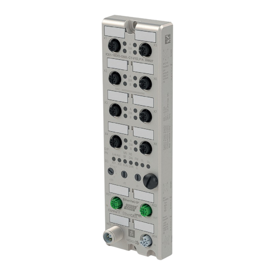
- Page 1 ICE11-8IOL-G60L-V1D Fieldbus Module with Multiprotocol Technology and IO-Link Manual...
- Page 2 Phone: +49 621 776 - 0 E-mail: info@de.pepperl-fuchs.com North American Headquarters Pepperl+Fuchs Inc. 1600 Enterprise Parkway Twinsburg, Ohio 44087 Phone: +1 330 425-3555 E-mail: sales@us.pepperl-fuchs.com Asia Headquarters Pepperl+Fuchs Pte. Ltd. P+F Building 18 Ayer Rajah Crescent Singapore 139942 Phone: +65 6779-9091 E-mail: sales@sg.pepperl-fuchs.com https://www.pepperl-fuchs.com...
-
Page 3: Table Of Contents
ICE11-8IOL-G60L-V1D Contents Introduction........................ 5 Content of this Document ................5 Manufacturer ....................5 Target Group, Personnel ................5 Symbols Used ....................6 Cybersecurity Information..................7 Product Description ....................9 Use and Application ..................9 Indicators and Operating Elements ............11 Interfaces and Connections ............... - Page 4 ICE11-8IOL-G60L-V1D Contents Commissioning for PROFINET ................80 Preparation ....................80 Configuration Example................80 7.2.1 Integration of PROFINET IO Modules in the TIA Portal ............. 81 7.2.2 Assignment of a Device Name and IP Address..............83 7.2.3 Configuring the IO-Link Channels ..................84 Parameterization of the Status/Control Module ..............88 7.2.4...
-
Page 5: Introduction
ICE11-8IOL-G60L-V1D Introduction Introduction Content of this Document This document contains information required to use the product in the relevant phases of the product life cycle. This may include information on the following: • Product identification • Delivery, transport, and storage •... -
Page 6: Symbols Used
ICE11-8IOL-G60L-V1D Introduction Symbols Used This document contains symbols for the identification of warning messages and of informative messages. Warning Messages You will find warning messages, whenever dangers may arise from your actions. It is mandatory that you observe these warning messages for your personal safety and in order to avoid prop- erty damage. -
Page 7: Cybersecurity Information
Security Context The ICE11-8IOL-G60L-V1D is intended for use in an automation network. This is a secure net- work with known and trusted participants that is separated (physically or logically) from the company network. - Page 8 ICE11-8IOL-G60L-V1D Cybersecurity Information The Following Measures Must Be Implemented on the Device for Commissioning: Change the device-specific password printed on the device. • Hardening: Access control with single factor authentication (SFA) • Special security Automatic login lock if access data is entered incorrectly after the sev-...
-
Page 9: Product Description
ICE11-8IOL-G60L-V1D Product Description Product Description Use and Application The module is a multiprotocol fieldbus module with 8 type A IO-Link master ports according to IO-Link standard V1.1.3. The G60L design in fully cast metal housing is resistant to mechanical damage and environ- mental influences. - Page 10 ICE11-8IOL-G60L-V1D Product Description Parameter storage • The Parameter Storage function stores and monitors the parameters of the IO-Link device and the IO-Link master. • This function makes it possible for you to easily replace the IO-Link device or the IO-Link master.
-
Page 11: Indicators And Operating Elements
ICE11-8IOL-G60L-V1D Product Description Indicators and Operating Elements Link/Act DIA BF E/IP x100 Channel indicator LED Status indicator LED Rotary switch Note The LEDs in the lower area of the Ethernet IO module have different names and functions depending on the selected protocol. The following LED descriptions are therefore divided into a general part (1), which is valid for all protocol settings, and LED descriptions for a specific protocol setting (2). - Page 12 ICE11-8IOL-G60L-V1D Product Description Indicators—General Part Description for LED A, B, DIA, U Function Green: Auxiliary sensor/actuator voltage OK • 18 V (± 1 V) < U < 30 V (± 1 V) : Auxiliary sensor/actuator voltage too low or too high •...
- Page 13 ICE11-8IOL-G60L-V1D Product Description EtherNet/IP Indicators E/IP areas: relevant LEDs Lnk/Act X01, Lnk/Act X02, MS, NS Function Lnk/Act X01 Green: Connected to an Ethernet node Lnk/Act X02 Yellow flashing: Ethernet node data exchange Off: No connection Green: Module ready for operation...
- Page 14 ICE11-8IOL-G60L-V1D Product Description EtherCAT Indicators EC area: relevant LEDs Lnk/Act X01, Lnk/Act X02, BF, DIA Function Lnk/Act X01 Green: Connected to an Ethernet node Lnk/Act X02 Yellow flashing: Ethernet node data exchange Off: No connection Red: No configuration, slow or no physical connection...
-
Page 15: Interfaces And Connections
ICE11-8IOL-G60L-V1D Product Description Interfaces and Connections The contact arrangements below show the front view of the plug-in area of the connectors. Fieldbus Connection X01, X02 Caution! Risk of destruction! Never route the power supply to the data cable. • Connection: M12 socket, 4-pin, D-coded •... - Page 16 ICE11-8IOL-G60L-V1D Product Description Figure 3.3 Schematic drawing of inputs/outputs 1–8 Port Signal Function IO-Link Class A, inputs/outputs IO-Link sensor power supply +24 V X1 ... X8 IN-x Channel B: digital input (type 1) IO-Link sensor power supply GND_U Channel A: IO-Link data exchange n.c.
-
Page 17: Dimensions
ICE11-8IOL-G60L-V1D Product Description Figure 3.4 Schematic drawing of M12 L-encoding (plug); port X03 (IN) Figure 3.5 Schematic drawing of M12 L-encoding (socket); port X04 (OUT) Port Signal Function Voltage supply (+24 V) Sensor/system supply X03, X04 GND U Ground/reference potential U... -
Page 18: Installation
ICE11-8IOL-G60L-V1D Installation Installation General Information Install the module with two M6x25/30 size screws on a level surface. The required torque is 1 Nm. Use washers according to DIN 125. For the installation holes, use a spacing of 237.3 mm to 239.7 mm. -
Page 19: Commissioning, Protocol Setting
ICE11-8IOL-G60L-V1D Commissioning, Protocol Setting Commissioning, Protocol Setting MAC Addresses Each device has 3 unique, manufacturer-assigned MAC addresses that cannot be changed by the user. The first assigned MAC address is printed on the device. This MAC address has no function for EtherCAT®. - Page 20 ICE11-8IOL-G60L-V1D Commissioning, Protocol Setting Figure 5.2 Select a module from those found. If the desired module is not displayed in the list of available nodes on the network, you can change the device filter and refresh the list. If the device still does not appear, please check your firewall settings.
-
Page 21: Iodd
ICE11-8IOL-G60L-V1D Commissioning, Protocol Setting IODD The IODD consists of a set of files that formally describe an IO-Link device. The IODD is cre- ated by the device manufacturer and is required for each IO-Link device. The device can use an IODD to facilitate IO-Link device configuration and make process data more readable to people. - Page 22 ICE11-8IOL-G60L-V1D Commissioning, Protocol Setting Setting a Protocol Multiprotocol modules have a total of three rotary switches. Move the first rotary switch X100 to the relevant switch position to set the protocol. For the other rotary switches, set the last two digits of the IP address when using EtherNet/IP.
- Page 23 ICE11-8IOL-G60L-V1D Commissioning, Protocol Setting EtherNet/IP If you use EtherNet/IP as the protocol, use rotary switch X100 to set the value 100 as the last octet of the IP address for the module. You can use rotary switch X100 to set a value of 0 to 2 for the IP address.
- Page 24 When restoring the factory settings, ensure that the module is connected to the voltage supply and switched on for at least 10 seconds. If it has been on for less than 10 seconds, the operat- ing system may be destroyed. The module would then need to be sent to Pepperl+Fuchs for repair.
-
Page 25: Commissioning For Ethernet/Ip
ICE11-8IOL-G60L-V1D Commissioning for EtherNet/IP Commissioning for EtherNet/IP Configuration The module supports implicit messaging and explicit messaging for EtherNet/IP communica- tion. I/O process data is transmitted cyclically; assembly object connections are transmitted via implicit messaging. Non-critical data with low priority, configuration settings and diagnostic data can be exchanged via acyclic messages using explicit messaging. - Page 26 ICE11-8IOL-G60L-V1D Commissioning for EtherNet/IP IO-Link Parameters, Exclusive Owner Connection Properties Parameter Content Connection name IO-Link (Exclusive Owner) Application type Exclusive owner Trigger mode Cyclic min. 1 ms Table 6.3 Connection Parameters, O -> T Parameter Content Real time transfer format...
-
Page 27: Configuration Parameters
ICE11-8IOL-G60L-V1D Commissioning for EtherNet/IP Parameter Content Data type INT (2 bytes) Table 6.7 Connection Parameters, T -> O Parameter Content Real time transfer format Pure data and modeless Connection type MULTICAST Assembly ID Data size 0 ... 446 bytes Data type INT (2 bytes) Table 6.8... - Page 28 ICE11-8IOL-G60L-V1D Commissioning for EtherNet/IP Byte Offset CIP Object Configuration Config Class 0xA0, Parameter Assembly Data Type Valid Values Instance 1 IO Mapping Mode SINT 0: Default Assign- Attribute 32 ment 1: Byte Swap 2: LSB Ch.A - MSB Ch.B 3: LSB Ch.B - MSB Ch.A...
- Page 29 ICE11-8IOL-G60L-V1D Commissioning for EtherNet/IP IO Mapping Mode The module supports five different I/O mapping modes for Digital Output Channel Control and the Input Channel Status. Modes 0 to 3 are predefined bit mappings. Mode 4 is a free user- defined mapping that can be used in conjunction with the I/O mapping of channel 1 ... 16 in the channel settings.
- Page 30 ICE11-8IOL-G60L-V1D Commissioning for EtherNet/IP Channel Settings CIP Object Byte Offset Class 0xA0, Configuration Config Instance 1 ... Parameter Assembly Data Type Valid Values IO Mapping (Ch1 ... SINT[16] 0 ... 15: Bit number of Attribute 1 16 channel process data...
- Page 31 ICE11-8IOL-G60L-V1D Commissioning for EtherNet/IP To use these parameters, it is necessary to configure the IO mapping mode of the general set- tings to Free IO Mapping (Mode 4). The default value for each parameter is its own channel number. DO Surveillance Timeout (Ch1 ... 16) The digital output channels are monitored during runtime.
- Page 32 ICE11-8IOL-G60L-V1D Commissioning for EtherNet/IP If a channel is set to "Normally Close", a high signal "0" is transmitted to the process input data, e.g., if an undamped sensor has a closed switching output. The channel LED indicates the physical input state of the port pin, regardless of these settings.
- Page 33 ICE11-8IOL-G60L-V1D Commissioning for EtherNet/IP IO-Link Diagnostic Settings Byte Offset Configuration Config CIP Object Class Parameter Assembly Data Type Valid Values 0xA2, Instance 1 IO-Link master SINT 0: Disable Attribute 1 Diagnostics 1: Enable IO-Link-Device SINT 0: Disable Attribute 2 Error...
- Page 34 ICE11-8IOL-G60L-V1D Commissioning for EtherNet/IP Settings IO-Link Port 1 ... 8 CIP Object Class Byte Offset 0xA3, Configuration Config Instance 1 ... Parameter Assembly Data Type Valid Values Output Data Size 224, 246, 268, SINT 0: No data Attribute 1 290,...
- Page 35 ICE11-8IOL-G60L-V1D Commissioning for EtherNet/IP CIP Object Class Byte Offset 0xA3, Configuration Config Instance 1 ... Parameter Assembly Data Type Valid Values Validation and Backup 233, 255, 277, SINT 0: No device check Attribute 10 299, and clear, no data 321, 343, 365,...
- Page 36 ICE11-8IOL-G60L-V1D Commissioning for EtherNet/IP Output Data Size The output data size of the respective IO-Link device can be configured with this parameter. There can be up to 32 bytes of IO-Link output data per port. The output data size of each IO-Link device has an influence on the total output data size of the connection.
- Page 37 ICE11-8IOL-G60L-V1D Commissioning for EtherNet/IP Raw IO-Link Data No "byte swap" Data Type WORD Data byte order: Byte 0, Byte 1 Sequence by "Swap": Byte 1, Byte 0 Data Type DWORD Data byte order: Byte 0, Byte 1, Byte 2, Byte 3 Sequence by "Swap": Byte 3, Byte 2, Byte 1, Byte 0...
- Page 38 ICE11-8IOL-G60L-V1D Commissioning for EtherNet/IP Validation and Backup This parameter enables the user to set the behavior of the IO-Link ports in relation to the type compatibility and data storage mechanism of the connected IO-Link device. The prerequisite for using Validation and Backup is that you configure the port mode to "IO-Link Manual."...
- Page 39 ICE11-8IOL-G60L-V1D Commissioning for EtherNet/IP Type-Compatible V1.1 Device with Restore, Download Master to Device Type-compatible with regard to IO-Link specification V1.1, which includes the validation of ven- dor ID and device ID. Only "Restore" is activated. Please note the following information on restore conditions: •...
-
Page 40: Process Data Assignment
ICE11-8IOL-G60L-V1D Commissioning for EtherNet/IP Process Data Assignment The module supports process data communication in both directions. In this context, "consum- ing data" is defined as the process output data that controls the physical outputs and IO-Link output data. In this context, "producing data" is defined as the process input data that contains the physical inputs, diagnoses and IO-Link input data with optional extended status and event data. - Page 41 ICE11-8IOL-G60L-V1D Commissioning for EtherNet/IP Producing Data Image, Input Actuator/ Diagno- Input Data Digital Input - General Diag- Sensor IO-Link Diag- IO-Link Input Frame Channel Status nosis Diagnosis nosis Data "Producing 2 bytes, INT 2 bytes, INT 2 bytes, INT 2 bytes, INT 0 byte 0 …...
- Page 42 ICE11-8IOL-G60L-V1D Commissioning for EtherNet/IP Sensor Diagnosis Sensor Diag- nostics Bit 7 Bit 6 Bit 5 Bit 4 Bit 3 Bit 2 Bit 1 Bit 0 Port number Byte 0, Byte 1, Table 6.25 X1 ... X8 Sensor short circuit at port X1 ... X8...
- Page 43 ICE11-8IOL-G60L-V1D Commissioning for EtherNet/IP If no IO-Link port is configured, the input_data image does not display IO-Link diagnosis. IO-Link Input Data IO-Link Port 1 [...] IO-Link Port 8 IO-Link Input Extende Extende Data Status d Status Events [...] Status d Status Events...
- Page 44 ICE11-8IOL-G60L-V1D Commissioning for EtherNet/IP Extended Status IO-Link Extended Status Bit 7 Bit 6 Bit 5 Bit 4 Bit 3 Bit 2 Bit 1 Bit 0 Extended Byte 0, Diagnostics Byte 1, Vendor ID Byte 2 Vendor ID, LSB Byte 3...
- Page 45 ICE11-8IOL-G60L-V1D Commissioning for EtherNet/IP Instance Unknown; "0", Reserved; Physical Layer PL; "1", Data Link Layer DL; "2", Ap- plication Layer AL; "3", Application; "4" Type Notification; "1", Warning; "2", Error; "3" Mode Event single shot; "1", Event disappeared; "2", Event appeared; "3"...
- Page 46 ICE11-8IOL-G60L-V1D Commissioning for EtherNet/IP Default Input Process Data Byte-Offset Input Data Digital input channel status, 2 bytes General diagnostics, 2 bytes Sensor diagnostics, 2 bytes Actuator diagnostics, 2 bytes IO-Link diagnostics, 6 bytes IO-Link port 1 data, status, 32 bytes...
- Page 47 ICE11-8IOL-G60L-V1D Commissioning for EtherNet/IP Example Process data images with modified data sizes The input data sizes and the output data sizes of the IO-Link ports and the presence of the extended status can be modified by the configuration group. You can decide which data is mapped to the process data.
- Page 48 ICE11-8IOL-G60L-V1D Commissioning for EtherNet/IP Modified process data Byte- Offset Output Data Input Data Digital output channel control, 2 bytes Digital input channel control, 2 bytes Reserved, 2 bytes General diagnostics, 2 bytes IO-Link port 1 data, control, 2 bytes Sensor diagnostics, 2 bytes...
-
Page 49: Configuration And Operation With Rockwell Automation Studio 5000
ICE11-8IOL-G60L-V1D Commissioning for EtherNet/IP Configuration and Operation with Rockwell Automation Studio 5000® The configuration and commissioning of the module described on the following pages refers to Rockwell Automation Studio 5000®, V30. If you are using an engineering tool from another pro- vider, please refer to the associated documentation. - Page 50 ICE11-8IOL-G60L-V1D Commissioning for EtherNet/IP Figure 6.2 Enter a name for the device and select the previously selected IP address. In this example, the name is ICE11 and the IP address is 192.168.1.1. Click on Change to change the settings for the device revision, the electronic coding and the connection type.
- Page 51 ICE11-8IOL-G60L-V1D Commissioning for EtherNet/IP You can see the selected connection in the Connection folder under Module Properties. In this folder, you can also define the Requested Packet Interval (RPI) and the EtherNet/IP connection type. A value of 1 ms is the minimum for the RPI parameter and the connection types Unicast or Multicast can be selected.
- Page 52 ICE11-8IOL-G60L-V1D Commissioning for EtherNet/IP The tag of the process data entered contains the device name followed by ":I.Data". The output process data has the same name followed by ":O.Data". Both arrays show the configured data sizes. See chapter 6.3. Figure 6.6 When the configuration is complete, the parameters can be downloaded to the EtherNet/IP controller.
- Page 53 ICE11-8IOL-G60L-V1D Commissioning for EtherNet/IP Using an AOI Navigate to Controller Organizer in your Studio 5000® project. Right-click on Add-On Instructions. Click on Import Add-On Instruction...: Figure 6.7...
- Page 54 ICE11-8IOL-G60L-V1D Commissioning for EtherNet/IP Open the *.L5X file: Figure 6.8 Click on OK to create the AOI with all the necessary User-Defined Data Types UDT: Figure 6.9...
- Page 55 ICE11-8IOL-G60L-V1D Commissioning for EtherNet/IP The imported components are displayed in the Controller Organizer: Figure 6.10 Check whether an error appears in the AOI tags as a red circle with a white cross. This can occur for the configuration data when you import an AOI into your system for the first time:...
- Page 56 ICE11-8IOL-G60L-V1D Commissioning for EtherNet/IP Figure 6.11 If no error has occurred, go to step 9. Go to Edit Tags and adjust the data type to the module-defined type on your system: Figure 6.12 The Config data type must exactly match the data type associated with ConfigData. Because this data type is system-dependent, you may need to select it manually.
- Page 57 ICE11-8IOL-G60L-V1D Commissioning for EtherNet/IP Figure 6.13...
- Page 58 ICE11-8IOL-G60L-V1D Commissioning for EtherNet/IP Edit the file name and save the AOI: Figure 6.14 To use the AOI, go to a logic, e.g., the MainRoutine. Add the IO-Link Master AOI to the current path "rung" via drag-and-drop: Figure 6.15...
- Page 59 ICE11-8IOL-G60L-V1D Commissioning for EtherNet/IP Right-click on the first element of the AOI and click on New Tag...: Figure 6.16 Enter a name and click on Create to create an AOI: Figure 6.17...
- Page 60 ICE11-8IOL-G60L-V1D Commissioning for EtherNet/IP Assign the module's input, output and configuration data: Figure 6.18 To create the tags for the remaining elements, repeat steps 10 and 11: Figure 6.19 Your logic no longer creates a copy of the input data and the output data simultaneously. It...
-
Page 61: Cip Object Classes
ICE11-8IOL-G60L-V1D Commissioning for EtherNet/IP Figure 6.20 CIP Object Classes 6.5.1 EtherNet/IP Object Classes According to the CIP specification, the module supports the following standard EtherNet/IP object classes: Object Class Object ID Instances Identity Object 0x01 0, 1 Message Router Object... - Page 62 ICE11-8IOL-G60L-V1D Commissioning for EtherNet/IP Identity Object 0x01 Supported services: • Get Attributes All 0x01 • Reset 0x05: • 0 = Reset Module, Warmstart • 1 = Reset to Factory Default • Get Attribute Single 0x0E Class Attribute, Instance 0 Attribute Name...
- Page 63 ICE11-8IOL-G60L-V1D Commissioning for EtherNet/IP Attribute Name Access Data Type Description Product Name STRING Human readable identification State USINT Present state of the device: 0 = Nonexistent 1 = Device Self Testing 2 = Standby 3 = Operational 4 = Major Recoverable Fault 5 = Major Unrecoverable Fault 6 ...
- Page 64 ICE11-8IOL-G60L-V1D Commissioning for EtherNet/IP Discrete Input Point Object 0x08 Supported services: • Get Attribute Single 0x0E Class Attribute, Instance 0 Attribute Name Access Data Type Description Revision UINT Revision of this object Table 6.40 Instance Attribute, Instance 1 ... 16...
- Page 65 ICE11-8IOL-G60L-V1D Commissioning for EtherNet/IP Attribute Name Access Data Type Description Capability Flags DWORD Flag description: b0: Announce-based Ring Node, "0" b1: Beacon-based Ring Node, "1" b2 ... 4: Reserved, "0" b5: Supervisor Capable, "0" b6: Redundant Gateway Capable, "0" b7: Flush_Table frame Capable, "1"...
- Page 66 ICE11-8IOL-G60L-V1D Commissioning for EtherNet/IP Attribute Name Access Data Type Description DSCP Explicit Get, Set USINT CIP UCMM, CIP transport class 2/3, All other EtherNet/IP encap- sulation messages, default value "27" Table 6.45 TCP/IP Object 0xF5 Supported services: • Get Attributes All 0x01 •...
- Page 67 ICE11-8IOL-G60L-V1D Commissioning for EtherNet/IP Attribute Name Access Data Type Description Configuration Control Get, Set DWORD Interface Control Flags: b0 ... 3: Configuration Method: 0 = Stored Value 1 = BOOTP 2 = DHCP 3 ... 15 = Reserved b4: DNS Enable "0"...
- Page 68 ICE11-8IOL-G60L-V1D Commissioning for EtherNet/IP Instance Attribute, Instance 1 ... 2 Attribute Name Access Data Type Description Interface Speed UDINT Current interface speed in Mbps Interface Flags DWORD Interface Flags: b0: Link Status b1: Half "0" or Full "1" Duplex b2 ... 4: Negotiation Status:...
- Page 69 ICE11-8IOL-G60L-V1D Commissioning for EtherNet/IP Attribute Name Access Data Type Description Interface Capability STRUCT Interface Capability Flags DWORD: b0: Manual Setting Requires Reset "0" b1: Auto-negotiate "1" b2: Auto-MDIX "1" b3: Manual Speed/Duplex "1" b4 ... 31: Reserved "0" Speed/Duplex Array Count of fol-...
-
Page 70: Manufacturer-Specific Object Classes
ICE11-8IOL-G60L-V1D Commissioning for EtherNet/IP Instance Attribute, Instance 1 Attribute Name Access Data Type Description LLDP Enable Get/Set STRUCT LLDP Enable Array Length (UINT): 1 + Class attribute 2 from the Ethernet Link Object (0xF6) = 3 LLDP Enable Array (BYTE): b0: Global Enable, LLDP Tx &... - Page 71 ICE11-8IOL-G60L-V1D Commissioning for EtherNet/IP General Settings Object 0xA0 Supported services: • Get Attribute Single 0x0E • Set Attribute Single 0x10 Class Attribute, Instance 0 Attribute Name Access Data Type Description Revision UINT Revision of this object Max. Instance UINT Maximum instance number of an...
- Page 72 ICE11-8IOL-G60L-V1D Commissioning for EtherNet/IP Instance Attribute, Instance 1 ... 16 Attribute Name Access Data Type Description IO Mapping Get, Set SINT 0 ... 15: Bit number of 16 channel process data 16: Inactive DO Surveillance Tim- Get, Set 0 ... 255...
- Page 73 ICE11-8IOL-G60L-V1D Commissioning for EtherNet/IP Instance Attribute, Instance 1 ... 16 Attribute Name Access Data Type Description IO-Link Master Diag- Get, Set BOOL 0: Disable nosis 1: Enable IO-Link Device Error Get, Set BOOL 0: Disable 1: Enable IO-Link Device Warn-...
- Page 74 ICE11-8IOL-G60L-V1D Commissioning for EtherNet/IP Attribute Name Access Data Type Description Input Data Swapping Get, Set SINT 0 ... 30 bytes 1<Default ¬¹ Font> Offset IOL Failsafe Get, Set SINT 0: Set Low 1: Set High 2: Hold Last 3: Replacement Value, trans-...
- Page 75 ICE11-8IOL-G60L-V1D Commissioning for EtherNet/IP Instance Attribute, Instance 1 ... 8 Attribute Name Access Data Type Description Failsafe value of IO- Get, Set Array of Depends on configured process Link port bytes data lengths, content must con- sider possible swapping configu-...
- Page 76 ICE11-8IOL-G60L-V1D Commissioning for EtherNet/IP Objective Protocol IO-Link Byte Data type Dependent on the device data type Endianness Content Data occurrence or error occurrence, max. 232 bytes Table 6.66 Set ISDU Data The index, subindex and IO-Link data must be set in the source data. The data length of the request depends on the data type of the IO-Link device.
- Page 77 ICE11-8IOL-G60L-V1D Commissioning for EtherNet/IP Error Code Descrip- Name Data Type tion Error Code IO-Link Device Error USINT Refer to IO-Link speci- fication IO-Link Device Addi- USINT Refer to IO-Link speci- tional Error fication Table 6.69...
-
Page 78: Message" Configuration In Rockwell Automation Studio 5000
ICE11-8IOL-G60L-V1D Commissioning for EtherNet/IP 6.5.3 "Message" Configuration in Rockwell Automation Studio 5000® Attributes of CIP object classes can be edited in Rockwell Automation Studio 5000® using the Message instruction. This requires the selection of the correct message and service type with the corresponding service code. - Page 79 ICE11-8IOL-G60L-V1D Commissioning for EtherNet/IP Get/Set ISDU Data The IO-Link device parameter object instance 1 ... n can be accessed with the manufacturer- specific Get/Set ISDU data service via the CIP object class ID, the instance ID and the attribute ID. The index and the subindex must be set in the source data. The IO-Link data must be appended for the Set ISDU data service.
-
Page 80: Commissioning For Profinet
To configure the modules in the control system, you need a GSD file in XML format. You can download this file from our website at https://www.pepperl-fuchs.com. The file for the PROFINET modules is named GSDML-V2.41-Pepperl+Fuchs-ICE11-yyyym- mdd. In this case, yyyymmdd is the issue date of the file. -
Page 81: Integration Of Profinet Io Modules In The Tia Portal
ICE11-8IOL-G60L-V1D Commissioning for PROFINET 7.2.1 Integration of PROFINET IO Modules in the TIA Portal Install the GSDML file for the desired module in the TIA portal. Once the GSDML file for the PROFINET modules has been installed, the modules are avail- able in the TIA portal hardware catalog. - Page 82 ICE11-8IOL-G60L-V1D Commissioning for PROFINET Click on the desired module in the hardware catalog. Drag and drop the module into the network view. Figure 7.3 Assign the module to the PROFINET network. Figure 7.4 Switch to the device configuration. Select the desired device to view the configuration options.
-
Page 83: Assignment Of A Device Name And Ip Address
ICE11-8IOL-G60L-V1D Commissioning for PROFINET 7.2.2 Assignment of a Device Name and IP Address Assignment of a unique device name and IP address PROFINET IO devices are addressed in the PROFINET network via a unique device name. This can be freely assigned by the user but must appear only once in the network. -
Page 84: Configuring The Io-Link Channels
ICE11-8IOL-G60L-V1D Commissioning for PROFINET Figure 7.8 Note Using a modified device name is not recommended for clarity reasons. 7.2.3 Configuring the IO-Link Channels By default, all channels are preconfigured as IO-Link I/O 32/32 bytes + PQI according to IO- Link specification V1.1.3. - Page 85 ICE11-8IOL-G60L-V1D Commissioning for PROFINET Deleting an IO-Link Channel Configuration To delete one or more IO-Link channels, select the desired IO-Link channel in "Device View." Device Overview Figure 7.10 Right-click on this entry. From the menu that appears, select the Delete option.
- Page 86 ICE11-8IOL-G60L-V1D Commissioning for PROFINET Creating an IO-Link Channel Configuration The I/O Module Submodules folder in the hardware catalog displays all configurable options that can be selected. IO-Link Channel Configuration Figure 7.12...
- Page 87 ICE11-8IOL-G60L-V1D Commissioning for PROFINET Select the desired option and then click and hold the left mouse button to drag the configuration to a free IO-Link sub-slot. Figure 7.13 The following options are available for the IO-Link C/Q channel (channel A/pin 4): Digital Input: In this mode the channel works as a digital input.
-
Page 88: Parameterization Of The Status/Control Module
ICE11-8IOL-G60L-V1D Commissioning for PROFINET 7.2.4 Parameterization of the Status/Control Module Status/Control Module Figure 7.14 Parameters in the status/control module: Figure 7.15 The status/control module in slot 1/sub-slot 1 is permanently preconfigured for each module. It contains 2 bytes of input data and 2 bytes of output data for the digital IO data plus status and control bits of the IO-Link master. - Page 89 ICE11-8IOL-G60L-V1D Commissioning for PROFINET Danger! Unexpected signals, machine movements Risk of injury or death! Unsupervised forcing can lead to unexpected signals and uncontrolled machine movements. • External Configuration Configuration and parameter data can be set via various external interfaces outside the GSDML configuration, e.g., web interface, REST, OPC UA, MQTT.
- Page 90 ICE11-8IOL-G60L-V1D Commissioning for PROFINET Legend UINT16 High-Byte / "low address" byte in a Siemens PLC UINT16 Low-Byte / "high address" byte in a Siemens PLC Applies when the Siemens PLC uses the Big Endian format Mode 1 Figure 7.18 Mode 2 Figure 7.19...
-
Page 91: Parameterization Of Io-Link Channels X1- X8
ICE11-8IOL-G60L-V1D Commissioning for PROFINET General Diagnostic Settings Diagnostic Settings for Modules with IO-Link Class A Ports Figure 7.23 • Report U supply voltage fault alarms The U supply voltage fault alarm can be set to "Disabled" or "Enabled" with this param- eter. - Page 92 ICE11-8IOL-G60L-V1D Commissioning for PROFINET Parameters of the IO-Link Channels Figure 7.25 Extended Port Parameters • Sensor Supply Mode Pin 1/L+ The sensor voltage at pin 1 is permanently active and cannot be deactivated. • DI Filter This parameter can be used to define the filter time of the digital input. The following options are available: Off;...
- Page 93 ICE11-8IOL-G60L-V1D Commissioning for PROFINET • Automatic Restart after Failure: If an output short-circuit or overload is detected, the output is switched off from the IO-Link master. However, after a time delay, the output is automatically switched on again to check whether the overload or short-circuit state is active.
- Page 94 ICE11-8IOL-G60L-V1D Commissioning for PROFINET • Swapping Offset: Swapping offset in bytes can be set depending on the configured I/O data length. If "2" is set, byte 3 is swapped. Default setting: 0 Failsafe Port Parameters for Ch. A in IO-Link Mode Figure 7.26...
- Page 95 ICE11-8IOL-G60L-V1D Commissioning for PROFINET Figure 7.28 Word data If the "Fail Safe Value(s)" option "Replacement Value" has been set, the replacement value entered in this input field(s) is used. The value must be entered as a decimal value. Depending on the configured data length, the values must be entered as bytes (0 –...
- Page 96 ICE11-8IOL-G60L-V1D Commissioning for PROFINET Input Fraction, Ch. A If the user configures a sub-slot module with less than the actual input data of the device, the IO-Link master sends as many IO-Link node input bytes as possible to the PLC, including the PQI byte of the sub-slot module.
- Page 97 ICE11-8IOL-G60L-V1D Commissioning for PROFINET Validation and Backup, Ch. A To use the validation and backup functionality of the IO-Link master, set the port mode to IO- Link - manual. Depending on the Validation and Backup setting, an entry in the Vendor ID and Device ID parameters is mandatory.
- Page 98 ICE11-8IOL-G60L-V1D Commissioning for PROFINET • Type-compatible (V1.1) IO-Link-Device with Restore: Type-compatible according to IO-Link specification V1.1, Vendor ID and Device ID are 2<Default ¬¹ Font> checked by the IO master with Restore IO-Link Device Parameter. 2<Default ¬¹ Font> Restore During the initial connection to an IO-Link node after activating this mode, the IO-Link...
-
Page 99: Io-Link Device Parameterization
ICE11-8IOL-G60L-V1D Commissioning for PROFINET Note An IO-Link device sets the upload flag independently if parameters have been written to the IO- Link device in block mode. 7.2.6 IO-Link Device Parameterization Siemens IO-Link Library You can use the SIEMENS "IO_LINK_DEVICE" function block (FB50001) to write or read out the data of an IO-Link node connected to the IO-Link master acyclically. - Page 100 ICE11-8IOL-G60L-V1D Commissioning for PROFINET SIEMENS WRREC and RDREC The read and write parameters from the PLC via the IO-Link master to the connected IO-Link nodes can also be called up via the SIEMENS function blocks SFB52/RDREC and SFB53/WREC. "Write" sequence of WRREC and RDREC calls Figure 7.31...
- Page 101 ICE11-8IOL-G60L-V1D Commissioning for PROFINET Note Unsigned16 values must be entered for PROFINET in Big Endian format. Control parameters Definition of Control octets Bit 7 Bit 6 Bit 5 Bit 4 Bit 3 Bit 2 Bit 1 Bit 0 Cancel / Release IOL_CALL...
- Page 102 ICE11-8IOL-G60L-V1D Commissioning for PROFINET Figure 7.33 Example: Data before "Writing" Figure 7.34...
- Page 103 ICE11-8IOL-G60L-V1D Commissioning for PROFINET Example: Data after "Writing" Figure 7.35...
- Page 104 ICE11-8IOL-G60L-V1D Commissioning for PROFINET Example: "Read" data after "Writing" Figure 7.36 "Read" sequence of the WRREC and RDREC calls Figure 7.37 The following table shows the sequence with sample data compared to FB50001. The FB50001 also uses the WRREC and RDREC blocks internally.
- Page 105 ICE11-8IOL-G60L-V1D Commissioning for PROFINET RDREC ID FB50001 Call WRREC RDREC RDREC Response ID (address proxy) (address (address proxy) proxy) PN_Index = 0xB400 PN_Index = 0xB400 Data Function 0x08 Unsigned8 Data Function 0x08 Header (fixed) Header (fixed) Port Port 1–8 Unsigned8 Port 1–8...
- Page 106 ICE11-8IOL-G60L-V1D Commissioning for PROFINET Figure 7.38 Figure 7.39...
- Page 107 ICE11-8IOL-G60L-V1D Commissioning for PROFINET Example: Data before "Reading" Figure 7.40...
- Page 108 ICE11-8IOL-G60L-V1D Commissioning for PROFINET Example: Data after "Reading" Figure 7.41...
- Page 109 ICE11-8IOL-G60L-V1D Commissioning for PROFINET Example: "Read" data after "Reading" Figure 7.42 Error PDU for the "Read/Write" sequence Offset Parameter Content Data type Port Error Error Codes detected by the Link- Unsigned16 ing Module or Client Error code IO-Link Error codes according to...
-
Page 110: Media Redundancy Protocol (Mrp)
ICE11-8IOL-G60L-V1D Commissioning for PROFINET Coding Port error code Definition Source 0x8000 Timeout No correct termina- Client tion of IOL_CALL (Resource Busy detection) 0x8001 Invalid port number Invalid port number or Client and/or Server port not supported 0x8002 Invalid IOL_Index Invalid Index... -
Page 111: Replacing Devices Without A Removable Medium/Programming Unit
ICE11-8IOL-G60L-V1D Commissioning for PROFINET Example: Setting up an MRP client in the TIA Portal® Figure 7.43 Example: Setting up Watchdog Time Monitoring in the TIA Portal® for the Use of MRP Figure 7.44 7.2.8 Replacing Devices without a Removable Medium/Programming Unit... -
Page 112: Identification And Maintenance Functions (I&M)
ICE11-8IOL-G60L-V1D Commissioning for PROFINET Figure 7.45 Note A network topology is configured based on the connections between PROFINET ports on the individual devices. This can be reached via slot 0 of the PROFINET devices in use. Displaying all non-linked ports allows you to specify a suitable partner port in each case. - Page 113 ICE11-8IOL-G60L-V1D Commissioning for PROFINET Supported I&M Functions I&M Data of the PN-IO Device To read (I&M 0–3) and write (I&M 1–3) I&M data, the corresponding hardware identifier for slot 0: PROFINET Interface X1 must be selected: TIA Portal® hardware identifier of the PROFINET interface for I&M 0-3 RDREC/WRREC Figure 7.47...
- Page 114 ICE11-8IOL-G60L-V1D Commissioning for PROFINET I&M 2 Length Data object [byte] Access Default value/description INSTALLATION_DATE Read/w 0x20 et seq. (empty) rite The supported data format is a visi- ble character string with a fixed length of 16 bytes; "YYYY-MM-DD hh:mm" or "YYYY- MM-DD"...
- Page 115 ICE11-8IOL-G60L-V1D Commissioning for PROFINET Length Data object [byte] Access Default value/description PROFILE_SPECIFIC_TYPE Read 0x0003 (IO module) IM_VERSION Read 0x0101 (I&M version 1.1) IM_SUPPORTED Read 0x0000 Table 7.14 I&M 0 (slot 0, index 0xAFF0) I&M Functions of the IO-Link Device IO-Link device-specific I&M 0 and I&M 5 data can be read out via slot 1 and the associated sub-slot 1 .
- Page 116 ICE11-8IOL-G60L-V1D Commissioning for PROFINET "Read" example I&M5 on port X1 with connected IOL device Figure 7.50 I&M 5 I&M 5 data Octets Data type Mapping rule IM_Annotation String (UTF8) "IO-Link Devices" IM_OrderID Visible String "Product Name" or "DeviceID" IM_VendorID Unsigned16 "VendorID"...
- Page 117 ICE11-8IOL-G60L-V1D Commissioning for PROFINET Reading and Writing I&M Data In its standard library, SIEMENS TIA Portal® offers system function blocks with which I&M data can be read and written. A data record contains a BlockHeader of 6 bytes and the I&M record.
- Page 118 ICE11-8IOL-G60L-V1D Commissioning for PROFINET Reading I&M Records I&M data can be read in the Siemens PLC using the standard RDREC function block (SFB52). The logical address of the slot/sub-slot (ID) and the I&M index (INDEX) must be used as han- dover parameters.
- Page 119 ICE11-8IOL-G60L-V1D Commissioning for PROFINET Example: "Read" I&M5 at port X1 with connected IOL device Figure 7.53 Writing I&M Records I&M data can be written in the Siemens PLC using the standard WRREC function block (SFB53). The logical address of the slot/sub-slot (ID), the I&M index (INDEX), and the data length (LEN) must be used as handover parameters.
-
Page 120: Prioritized Start-Up/Fast Start-Up (Fsu)
ICE11-8IOL-G60L-V1D Commissioning for PROFINET 7.2.10 Prioritized Start-Up/Fast Start-Up (FSU) Devices with Fast Start-Up (FSU) function support optimized system start-up. This ensures faster restarting after the power supply is restored. Fast Start-Up can be activated using PROFINET interface [X1] > Advanced options > Interface options (PROFINET interface [X1] >... -
Page 121: Suspend / Resume" Of The Io-Link Port Control
ICE11-8IOL-G60L-V1D Commissioning for PROFINET 7.2.11 "Suspend / Resume" of the IO-Link Port Control Use Case of the Automatic Tool Change Function Depending on the status of a production process, a tool change is necessary within a machine, which is usually carried out by disconnecting a specific tool such as a gripper and by subse- quently connecting another tool. - Page 122 ICE11-8IOL-G60L-V1D Commissioning for PROFINET • Successful "Resumed Port operation" results in the flag bit display "PortActive" = 1 Use Cases Inspection level (backup & Use case restore) Description No. 1: A device is replaced by 0: No device check In use case no. 1, all inspec-...
- Page 123 ICE11-8IOL-G60L-V1D Commissioning for PROFINET ID = 0 Figure 7.58 ID = 0 to address the IO-Link master proxy INDEX = 0xB400 LEN = 8 bytes for commands WRREC Data Figure 7.59 Read Record Suspend - Port status Use this request to verify that the previous writing of the "Suspend" port command was successful.
- Page 124 ICE11-8IOL-G60L-V1D Commissioning for PROFINET ID = 0 to address the IO-Link master proxy INDEX = 0xB400 LEN = 12 bytes, 8 bytes for commands + 4 bytes for the error PDU If the "Suspend" port command was successful, the read data looks as follows: Figure 7.61...
- Page 125 ICE11-8IOL-G60L-V1D Commissioning for PROFINET Figure 7.62 WRREC Data Figure 7.63 Read Record Resume - Port status Use this request to verify that the previous writing of the "Resume" port command was successful. Figure 7.64...
-
Page 126: Bit Assignment
ICE11-8IOL-G60L-V1D Commissioning for PROFINET ID = 0 to address the IO-Link master proxy INDEX = 0xB400 LEN = 12 bytes, 8 bytes for commands + 4 bytes for the error PDU If the "Resume" port command was successful, the read data looks as follows: Figure 7.65... - Page 127 ICE11-8IOL-G60L-V1D Commissioning for PROFINET Process Data Status / Control Module, Slot 1 / Sub-slot 1 The status/control module has an Unsigned16 for digital input data and an 1<Default ¬¹ Font> Unsigned16 for digital output data. Status data (input) The two Unsigned16 input bytes contain the status of the digital inputs. For the digital A channel inputs, the data is also available in the input byte of the corresponding sub-slot module.
- Page 128 ICE11-8IOL-G60L-V1D Commissioning for PROFINET Mode 4 Status/control Bit 7 Bit 6 Bit 5 Bit 4 Bit 3 Bit 2 Bit 1 Bit 0 Slot UINT16 Low Byte UINT16 High Byte Table 7.22 Digital input/output mapping mode 4 Mode 5 The mapping for mode 5 depends on the user settings.
- Page 129 ICE11-8IOL-G60L-V1D Commissioning for PROFINET Input Data: Sub-Slots 1.2–1.9 INPUT Input Bit 7 Bit 6 Bit 5 Bit 4 Bit 3 Bit 2 Bit 1 Bit 0 Slot 1.1 X1 Byte 1–33 • If the IO-Link port is in "Digital-In" mode, the status is set to "DI- C/Q"...
- Page 130 ICE11-8IOL-G60L-V1D Commissioning for PROFINET Output Data: Sub-Slots 1.2–1.9 INPUT Input Bit 7 Bit 6 Bit 5 Bit 4 Bit 3 Bit 2 Bit 1 Bit 0 Slot 1.1 X1 Byte 1–32 • If the IO-Link port is in "Digital-Out" mode, the state is set to "DO- C/Q"...
-
Page 131: Commissioning For Ethercat
ICE11-8IOL-G60L-V1D Commissioning for EtherCAT Commissioning for EtherCAT EtherCAT EtherCAT® is a registered trademark amd patented technology, licensed by Beckhoff Automa- tion GmbH, Germany. Preparation Downloading and Installing the ESI File An ESI file (EtherCAT Slave Information file) is required to configure a module in the controller. -
Page 132: Configuration
ICE11-8IOL-G60L-V1D Commissioning for EtherCAT 8.3.1 Configuration Input Data PDO content Size Type Index [byte] Index Size Type Name Input 0x1A00 32 0x6000:01 UINT32 1 byte IO-Link input data 0x6000:32 UINT32 32 byte IO-Link input data 0x1A01 32 0x6010:01 UINT32 1 byte IO-Link input data... - Page 133 ICE11-8IOL-G60L-V1D Commissioning for EtherCAT PDO content Size Type Index [byte] Index Size Type Name Input 0x1A80 8 0xF100:01 UINT32 IO-Link connector status 1 0xF100:02 UINT32 IO-Link connector status 2 0xF100:03 UINT32 IO-Link connector status 3 0xF100:04 UINT32 IO-Link connector status 4...
- Page 134 ICE11-8IOL-G60L-V1D Commissioning for EtherCAT PDO content Size Type Index [byte] Index Size Type Name Output 0x1606 0x7060:01 UINT32 1. bytes of IO-Link output data 0x7060:32 UINT32 32. bytes of IO-Link output data 0x1607 0x7070:01 UINT32 1. bytes of IO-Link output...
- Page 135 ICE11-8IOL-G60L-V1D Commissioning for EtherCAT Slot Description IOL_O_32byte IO-Link, 32 bytes as process data output IOL_I/O_1/1byte IO-Link • 1 byte as process data input • 1 byte as process data output IOL_I/O_2/2byte IO-Link • 2 bytes as process data input •...
-
Page 136: Device Parameters
ICE11-8IOL-G60L-V1D Commissioning for EtherCAT 8.3.2 Device Parameters The modules support different parameters. The parameters are sent to the module during com- missioning of the controller. The following parameters can be set: Extended Parameters SDO content Index Size [byte] Index Size... - Page 137 ICE11-8IOL-G60L-V1D Commissioning for EtherCAT Digital outputs mode SDO content Index Size [byte] Index Size Type Name/description 0x2380 0x2380:01 UINT8 Port 1 Channel A 0 = Set Low 1 = Set High 2 = Hold Last Other = Reserved 0x2380:02 UINT8...
- Page 138 ICE11-8IOL-G60L-V1D Commissioning for EtherCAT SDO content Index Size [byte] Index Size Type Name/description 0x2380 0x2380:12 UINT8 Port 6 Channel B 0 = Set Low 1 = Set High 2 = Hold Last Other = Reserved 0x2380:13 UINT8 Port 7 Channel A...
- Page 139 ICE11-8IOL-G60L-V1D Commissioning for EtherCAT General device settings SDO content Index Size [byte] Index Size Type Name/description 0x2381 0x2381:01 BOOL Web interface locked 0 = false 1 = true 0x2381:02 BOOL Force mode locked 0 = false 1 = true 0x2381:03...
- Page 140 ICE11-8IOL-G60L-V1D Commissioning for EtherCAT Surveillance Timeout The module firmware allows you to set a delay time before monitoring of output currents begins. The delay time is also known as “Surveillance Timeout”. You can define this for each individual output channel.
- Page 141 ICE11-8IOL-G60L-V1D Commissioning for EtherCAT Digital I/O Mode, Channel B The "Digital I/O mode" parameter allows the input/output channels (I/O channels) of channel B of the module to be configured. The following settings are possible: 1 = Input 2 = Output...
- Page 142 ICE11-8IOL-G60L-V1D Commissioning for EtherCAT Digital Inputs Mode The device supports the configuration of the digital input logic of channel A (pin 4) and channel B (pin 2) of the IO-Link port. SDO content Index Size [byte] Index Size Type Name/description...
- Page 143 ICE11-8IOL-G60L-V1D Commissioning for EtherCAT Digital Input Filters The device supports the configuration of a digital input filter for channel A (pin 4) and channel B (pin 2) of the IO-Link port. SDO content Index Size [byte] Index Size Type Name/description...
- Page 144 ICE11-8IOL-G60L-V1D Commissioning for EtherCAT Timeout Before Restart The device supports the configuration of a pre-reboot digital output timeout for channel A (pin 4) and channel B (pin 2) of the IO-Link port. SDO content Index Size [byte] Index Size Type...
- Page 145 ICE11-8IOL-G60L-V1D Commissioning for EtherCAT Additional IO-Link Port Settings SDO content Size Index [byte] Index Size Type Name/description 0x30n0:01 UINT8 Swap mode 0x30n0 0x30n0:02 UINT8 Swap length 0x30n0:03 UINT8 Swap offset 0x30n0:04 BOOL Sensor supply activated 0 = false 1 = true...
- Page 146 ICE11-8IOL-G60L-V1D Commissioning for EtherCAT IO-Link Parameterization SDO content Size Index [byte] Index Size Type Name/description 0x40n0:01 UINT8 Control panel 0x40n0 0x00 = no action 0x02 = write 0x03 = read 0x40n0:02 UINT8 Status 0x00 = no activity 0x01 = active/occupied...
- Page 147 ICE11-8IOL-G60L-V1D Commissioning for EtherCAT SDO content Size Index [byte] Index Size Type Name/description 0x80n0:37 UINT8 Number and structure of the process output data "ProcessDataOut" = value in IO-Link format acc. to version 1.0 of the IO-Link specifica- tion Bit 0 ... 4 = length Bit 5 = reserved Bit 6 = SIO indicator.
- Page 148 ICE11-8IOL-G60L-V1D Commissioning for EtherCAT SDO content Size Index [byte] Index Size Type Name/description 0x90n0:33 UINT8 Frame functions 0x90n0:34 UINT8 Cycle time 0x90n0:35 UINT8 Offset 0x90n0:36 UINT8 Number and structure of the process input data "ProcessDataIn" = value in IO-Link format acc.
-
Page 149: Configuration Example With Twincat® 3
ICE11-8IOL-G60L-V1D Commissioning for EtherCAT 8.3.3 Configuration Example with TwinCAT® 3 The configuration and commissioning of the modules described below refers to the software TwinCAT® 3 from Beckhoff Automation GmbH. The configuration is based on the example of an ICE1-16DIO-G60L-V1D module. For other module versions, configuration is carried out with a few minor changes. - Page 150 ICE11-8IOL-G60L-V1D Commissioning for EtherCAT Figure 8.2 In the "Add Route Dialog" menu, click on the "Broadcast Search” button. Figure 8.3 TwinCAT® lists the found nodes in the menu. Click on the desired device. In this example, "CX-19FDE4" for the PLC.
- Page 151 ICE11-8IOL-G60L-V1D Commissioning for EtherCAT Figure 8.4 In the "Address Info" area, change the setting to "IP Address." Then click on the “Add Route” button. Figure 8.5 You will be prompted to create a password, but this is not necessary. Click on the "OK" button...
- Page 152 ICE11-8IOL-G60L-V1D Commissioning for EtherCAT Figure 8.6 Click on the “Close” button in the "Add Route Dialog" menu. Figure 8.7 To save the connection to "CX-19FDE4" in the project, click on "CX-19FDE4" again within the "Choose Target System” dialog that is still open.
- Page 153 ICE11-8IOL-G60L-V1D Commissioning for EtherCAT Figure 8.8 Click on the “OK” button to confirm the save. Now the status in TwinCAT will change from "Local" to "CX-19FDE4" In the left-hand working area of “Solution Explorer”, switch to the option "I/O." .
- Page 154 ICE11-8IOL-G60L-V1D Commissioning for EtherCAT Figure 8.10 In the "Device Found At" dialog, select the port for your PLC. In this example, the port is "PCI\TcI8254x1" Figure 8.11 Click on the "OK" button to confirm the selection. " Open the configuration tab for the TwinCAT project by double-clicking on "Device 3.”...
- Page 155 ICE11-8IOL-G60L-V1D Commissioning for EtherCAT Figure 8.12 If you have not already done so, select the network adapter and install the driver for EtherCAT real-time communication. Click on the "Adapter" tab and then on "Compatible Devices ..." to select and install the...
- Page 156 ICE11-8IOL-G60L-V1D Commissioning for EtherCAT Integrating the Ethernet IO Module Select the device. To do so, navigate to "Device 1 (EtherCAT)," right-click on "Devices" and select the option "Add New Item.." Figure 8.13 Select the desired module. Figure 8.14 Note Selecting a profile as follows is only possible on 16DIO modules such as ICE1- 16DIO-G60L-V1D and ICE1-16DIO-G60L-C1-V1D.
- Page 157 ICE11-8IOL-G60L-V1D Commissioning for EtherCAT Figure 8.15 Click on the "OK" button to confirm the selection. Note The default standard PDOs will be used according to the profile selected. If necessary, you may change the I/O profile by carrying out the following steps.
- Page 158 ICE11-8IOL-G60L-V1D Commissioning for EtherCAT Caution! Caution during parameter changes If you change the I/O profile having changed the parameter settings on the “Start-Up” tab, the parameters on the “Start-Up” tab will remain as changed. If this is the case, delete the device from the configuration and then add it again.
- Page 159 ICE11-8IOL-G60L-V1D Commissioning for EtherCAT Figure 8.18 Navigate to the "Start-Up" tab and check the default device parameter settings. Figure 8.19...
- Page 160 ICE11-8IOL-G60L-V1D Commissioning for EtherCAT In order to change a parameter setting, double-click on a parameter, then the “Edit” dialog box will open. The new value can be entered in the data entry panel. Figure 8.20 Click on the "OK" button to confirm the entries.
- Page 161 ICE11-8IOL-G60L-V1D Commissioning for EtherCAT Figure 8.21 Click on the "Advanced Settings” button. Navigate to the "EoE" entry under the "Mailbox” option. Figure 8.22 If no web server services are to be used, disable the "Virtual Ethernet Port" option by clicking on the tick.
- Page 162 ICE11-8IOL-G60L-V1D Commissioning for EtherCAT Activating Configuration If the module is connected to the EtherCAT network, select "TWINCAT" in the menu bar and then "Activate Configuration." Figure 8.23 Caution! Personal injury and property damage Before you adjust the inputs or outputs of the module, make sure that no per- sonal injury or property damage can occur.
- Page 163 ICE11-8IOL-G60L-V1D Commissioning for EtherCAT Figure 8.24 Click on the "Write" button to set a module output. Note Configuration of the PLC and module is now complete. You may now create your user program.
-
Page 164: The Integrated Web Server
ICE11-8IOL-G60L-V1D the Integrated Web Server the Integrated Web Server The module has an integrated web server that provides functions for configuring modules, and displaying status and diagnostic information. The web interface provides an overview of the module configuration and status. It can also be used to adjust specific settings, perform a restart, reset to factory settings, and update firm- ware. - Page 165 ICE11-8IOL-G60L-V1D the Integrated Web Server Ports (Connection Side) Click the "Ports" tab in the menu bar of the start window. A new window opens with the details of the individual ports: Figure 9.2 The Port Details page displays all information about the selected port. The left column displays all port and channel-specific information.
- Page 166 ICE11-8IOL-G60L-V1D the Integrated Web Server If a suitable IODD for the currently connected device already exists in the system memory, the CONFIGURE button is displayed in the interface. Clicking on the button opens the Parameters page to configure the device.
- Page 167 ICE11-8IOL-G60L-V1D the Integrated Web Server System Page Click the "System" tab in the menu bar of the start window. A new window opens with informa- tion on the system of the module: Figure 9.4 This page contains information about the following values and parameters: •...
- Page 168 ICE11-8IOL-G60L-V1D the Integrated Web Server • Restart device • The module initializes a software reset. • Reset configuration to factory defaults • The module restores the default factory settings. Note During a factory reset, the "BF/MS/RUN" LED will light up red three times. Once reset to the factory settings, the "BF/MS/RUN"...
- Page 169 ICE11-8IOL-G60L-V1D the Integrated Web Server The IODD Management page can be accessed from the System page and displays all IODDs that are currently stored in the system. All IODDs that match connected devices are marked. On the IODD Management page, you can manually delete each IODD in the system.
- Page 170 Click on the "Contact" tab in the menu bar of the start window. A new window with the contact data of Pepperl+Fuchs opens: Figure 9.8 The address of the contact page is: http://[IP address]/contact.htm This page provides information about Pepperl+Fuchs Group contact details.
-
Page 171: Iiot Functionality
ICE11-8IOL-G60L-V1D IIoT Functionality IIoT Functionality The device offers interfaces and functions for optimal integration into existing or future IIoT net- works. The device continues to function as a fieldbus node that can communicate with a PLC and be controlled by it. The device offers common IIoT interfaces that enable communication channels alongside the PLC. - Page 172 ICE11-8IOL-G60L-V1D IIoT Functionality Element Data Type Description Example login string Username for MQTT broker "admin" Default: null password string Password for MQTT broker "private" Default: null port number Broker port 1883 base-topic string Base topic "iomodule_[mac]" Default: "ice11" will-enable boolean...
- Page 173 ICE11-8IOL-G60L-V1D IIoT Functionality • Parameters with an incorrect data type cause an error. Writing all available parameters at once is not permitted. You should write only one or a small number of parameters at a time. Example {"status": -1, "error": [{"Element": "publish-interval", "Message": "Integer expected"}]}...
- Page 174 ICE11-8IOL-G60L-V1D IIoT Functionality Often there is a topic for all gateway-related information and topics for each port. All identity topics are published only once when the device is started, as this information should be static. All other topics are either published at a fixed interval or triggered manually, depending on their configuration.
- Page 175 ICE11-8IOL-G60L-V1D IIoT Functionality Publish-Topic Overview of all Publish JSON data for the defined topics: Identity/Gateway Input Data Type json_string ordering_number json_string device_type json_string serial_number json_string mac_address json_string production_date json_string fw_name json_string fw_date json_string fw_version json_string hw_version json_string vendor_name json_string vendor_address...
- Page 176 ICE11-8IOL-G60L-V1D IIoT Functionality Status/Gateway Input Data Type Scope Default Notes protocol json_string wait_for_io_system wait_for_io_Connec- tion failsafe connected error ethernet_port1 json_string 100_mbit/s_full 100_mbit/s 10_mbit/s_full 10_mbit/s ethernet_port2 json_string 100_mbit/s_full 100_mbit/s 10_mbit/s_full 10_mbit/s module_restarts json_integer 0 ... 4294967295 channel_diagnostics json_boolean true / false...
- Page 177 ICE11-8IOL-G60L-V1D IIoT Functionality Input Data Type Scope Default Notes channel_chb json_string input/output input output io_link Table 10.10 Config/Port/1 ... 8 Input Data Type Scope Default Notes port json_integer 1 ... 8 direction_cha json_string input/output input output direction_chb json_string input/output input...
- Page 178 ICE11-8IOL-G60L-V1D IIoT Functionality If the configuration allows commands in principle, the device subscribes to special command topics, through which it can receive commands from other MQTT clients. The command topic is based on the base topic. It always has the following form: [base-topic]/command After the command topic, fixed topics are for various writable objects.
- Page 179 ICE11-8IOL-G60L-V1D IIoT Functionality There are several specification values specified for the portmodeConfig object property: Config Object: Portmode Property Data Type Example Remarks port integer string "dio", "di", "do", "iol", channelA "off" string "dio", "di", "do", "iol", channelB "off", "aux" inlogicA string "no", "nc"...
- Page 180 ICE11-8IOL-G60L-V1D IIoT Functionality MQTT Configuration via JSON Depending on your application, download and install Insomnia or a similar application: insomnia.rest/download/. Configure MQTT POST: [IP-address]/w/config/mqtt.json Figure 10.1 Read MQTT from: GET: [IP-address]/r/config/mqtt.json...
-
Page 181: Opc Ua
ICE11-8IOL-G60L-V1D IIoT Functionality Figure 10.2 10.2 OPC UA OPC Unified Architecture is a platform-independent standard with a service-oriented architec- ture for communication in and with industrial automation systems. The OPC UA standard is based on the client-server principle and allows machines and devices to communicate horizontally with each other and vertically with the ERP system or the cloud, regardless of preferred fieldbuses. - Page 182 ICE11-8IOL-G60L-V1D IIoT Functionality Unsupported OPC UA Features within the "IO-Link Companion Specification" Function Support Managing IODDs Not supported (Section 6.1.6 in the specification) Mapping IODD information to OPC UA ObjectTypes Not supported (Section 6.3 in the specification) IOLinkIODDDeviceType Not supported (Section 7.2 ff.
- Page 183 ICE11-8IOL-G60L-V1D IIoT Functionality All configuration elements are optional and not bound to any particular order. Not every ele- ment needs to be sent. This means that only configuration changes are applied. Optional: The configuration parameters of OPC UA can be set directly via the web interface.
- Page 184 ICE11-8IOL-G60L-V1D IIoT Functionality Figure 10.3 Read MQTT from: GET: [IP-address]/r/config/opcua.json Figure 10.4...
-
Page 185: Rest Api
ICE11-8IOL-G60L-V1D IIoT Functionality 10.3 REST API The REST API is a programmable interface that uses HTTP requests for GET and POST data. This allows access to detailed device information. With the gateway, the REST API can be used to read out the device status. The REST API can also be used to write configuration and forcing data. - Page 186 ICE11-8IOL-G60L-V1D IIoT Functionality Function Supported Devices GET /devices GET /capabilities GET /identification POST /identification GET /processdata/value GET /processdata/getdata/value GET /processdata/setdata/value POST /processdata/value GET /parameters GET /parameters/{index}/subindices GET /parameters/{parameterName}/subindices GET /parameters/{index}/value GET /parameters/{index}/subindices/{subindex}/value GET /parameters/{parameterName}/value GET /parameters/{parameterName}/subindices/ {sub- ParameterName}/value POST /parameters/{index}/value...
- Page 187 ICE11-8IOL-G60L-V1D IIoT Functionality Structure STANDARD Object Name Data type Description Example Name string Device name "ICE11-8IOL-G60L- V1D" order id string Ordering number "70146527" fw-version string Firmware version "V.1.1.0.0 - 01.01.2021" hw-version string Hardware version "V.1.00" string MAC address of the "3C B9 A6 F3 F6 05"...
- Page 188 ICE11-8IOL-G60L-V1D IIoT Functionality Name Data type Description Example diag array of numbers (4) Diagnostic information: Element 0 = 1 Byte: Bit 7: Internal module error (IME) Bit 6: Forcemode active Bit 3: Actuator short Bit 2: Sensor short Bit 1: UL fault...
- Page 189 ICE11-8IOL-G60L-V1D IIoT Functionality CHANNEL Object Name Data type Description Example Name string Name of channel type number Hardware channel type as number: 0 = DIO 1 = Input 2 = Output 3 = Input/Output 4 = IO-Link 5 = IOL AUX 6 = IOL AUX with DO 7 = IOL AUX with DO.
- Page 190 ICE11-8IOL-G60L-V1D IIoT Functionality Name Data type Description Example iolink_text string Textual representation "Digital Input" of the current port mode aux_mode number Indicates the config- ured mode for the Pin 0 = No AUX 1 = AUX output 2 = Digital output...
- Page 191 ICE11-8IOL-G60L-V1D IIoT Functionality DEVICE Object Name Data type Description Example device_id number vendor_id number serial string baudrate string Baudrate (COM1,2,3) cycle_time number Cycle time in micro- seconds input_len array of numbers (n) IOL input length in bytes output_len array of numbers (n)
- Page 192 ICE11-8IOL-G60L-V1D IIoT Functionality Configuration and Forcing Method: POST URL: <ip>/w/force.json Parameter: n.a. Format: JSON ROOT Object Name Data type Description Example forcemode boolean Forcing authority true / false on/off portmode array (Port mode object) digital array (Digital object) array (IOL object) Table 10.29...
- Page 193 ICE11-8IOL-G60L-V1D IIoT Functionality IOL Object Name Data type Description Example port integer 0– 7 output array[integer] or null to Output forcing [55,88,120] clear forcing input array[integer] or null to Input simulation to [20,0,88] clear forcing Table 10.32 Reading and Writing of ISDU Parameters...
- Page 194 ICE11-8IOL-G60L-V1D IIoT Functionality Name Data type Description Example status integer 0 = no error 0, -1 -1= an error occurred eventcode integer IOL eventcode if sta- tus is -1 data array[integer] data, if no error occurred. otherwise null Table 10.35...
-
Page 195: Coap Server
ICE11-8IOL-G60L-V1D IIoT Functionality Example Reading out ISDU ISDU read request: {"ix":5,"subix":0}, {"ix":18,"subix":0}, {"ix":19,"subix":0}, {"ix":20,"subix":0} Response: "message":"OK", "data": {"ix":5,"subix":0,"status":-1,"eventcode":32785}, {"ix":18,"subix":0,"data":[79,68,83,49,48,76,49,46,56,47,76,65,54,44 ,50, 48,48,45,77,49,50],"status":0}, {"ix":19,"subix":0,"data":[53,48,49,50,57,53,51,53],"status":0}, {"ix":20,"subix":0,"data":[100,105,115,116,97,110,99,101,32,115,101, 110, 115,111,114],"status":0} "status":0} Example Writing IDSU ISDU write request: {"ix":24,"subix":0,"data":[97,98,99,100,101,102]}, {"ix":9,"subix":0,"data":[97,97,97,97,97,98]} ] Response: "message":"OK", "data": {"ix":24,"subix":0,"status":0}, {"ix":9,"subix":0,"eventcode":32785,"status":-1} "status":0}... - Page 196 ICE11-8IOL-G60L-V1D IIoT Functionality CoAP Configuration The CoAP functions are deactivated in the factory settings. The CoAP server can be config- ured either by using the web interface or directly through a JSON object sent in an "HTTP request". The configuration URL is: http://[ip-address]/w/config/coapd.json The configuration can also be read back as a JSON file: http://[ip-address]/r/con- fig/coapd.json...
- Page 197 ICE11-8IOL-G60L-V1D IIoT Functionality Type Note /r/config/coapd.json /r/config/syslog.json /contact.json /fwup_status /iolink/v1/gateway/identification /iolink/v1/gateway/capabilities /iolink/v1/gateway/configuration /iolink/v1/gateway/events /iolink/v1/masters /iolink/v1/masters/1/capabilities /iolink/v1/masters/1/identification /iolink/v1/masters/1/ports /iolink/v1/masters/1/ports/{port_number}/capabilities The API is available for all 8 ports. {port_number} should be selected between "1" and "8". /iolink/v1/masters/1/ports/{port_number}/status The API is available for all 8 ports.
- Page 198 ICE11-8IOL-G60L-V1D IIoT Functionality COAP Configuration via JSON Depending on your application, download and install Insomnia or a similar application: insomnia.rest/download/. Configure CoAP POST: [IP-address]/w/config/coapd.json Figure 10.5 Read CoAP from: GET: [IP-address]/r/config/coapd.json...
-
Page 199: Syslog
ICE11-8IOL-G60L-V1D IIoT Functionality Figure 10.6 10.5 Syslog The gateway provides a syslog client that can connect to a configured syslog server and is able to log messages. Syslog is a platform-independent standard for logging messages. Each message contains a timestamp and information about the severity level and subsystem. The Syslog protocol RFC5424 is based on the server-client principle and allows machines and devices to send and centrally collect messages in the network. - Page 200 ICE11-8IOL-G60L-V1D IIoT Functionality Syslog Configuration Name Data type Description Example syslog-enable boolean Master switch for the true/false syslog client global-severity integer Message level of the 0/1/2/3/4/5/6/7 syslog client: 0 = Emergency 1 = Alert 2 = Critical 3 = Error...
- Page 201 ICE11-8IOL-G60L-V1D IIoT Functionality Syslog Configuration - Quick Start Caution! Third party Lumberg Automation assumes no responsibility for any content contained on the referenced websites and does not guarantee the functionality of the third-party software mentioned above. Syslog Configuration via JSON Depending on your application, download and install Insomnia or a similar application: insomnia.rest/download/.
-
Page 202: Ntp
ICE11-8IOL-G60L-V1D IIoT Functionality Figure 10.8 10.6 The gateway provides an NTP client in version 3, which can connect to a configured NTP server. The NTP client is able to synchronize network time at a configurable interval. NTP is a network protocol that uses UDP datagrams to send and receive timestamps to syn- chronize them with a local clock. - Page 203 ICE11-8IOL-G60L-V1D IIoT Functionality NTP Configuration Name Data type Description Example NTP client status boolean Master switch for the NTP client true/false 1/2/10/60 Server address string NTP server IP address 192.168.1.50 Server port integer Port of the NTP server Update interval...
- Page 204 ICE11-8IOL-G60L-V1D IIoT Functionality Figure 10.9 Read NTP from: GET: [IP-address]/r/config/ntpc.json Figure 10.10...
-
Page 205: Troubleshooting
ICE11-8IOL-G60L-V1D Troubleshooting Troubleshooting 11.1 Diagnostics Indicator in the Integrated Web Server The module shows the error diagnostics on the connection page of the integrated web server. For information on how to call up the connection page, . Figure 11.1 Diagnostic data is displayed in the "Port Diagnosis" area of the connection page, according to the connection. - Page 206 ICE11-8IOL-G60L-V1D Troubleshooting Evaluating Alarms in the TIA portal If a diagnostics alarm is triggered, the user program in the TIA portal is interrupted and a diag- nostics block is called. The following blocks are used: Cause OB call Diagnostics alarm (short circuit, overload, wire break, low voltage on an I/O...
-
Page 207: Diagnostic Processing Via Ethernet/Ip
ICE11-8IOL-G60L-V1D Troubleshooting Display of diagnosis in the TIA Portal Select the faulty I/O module in the hardware manager and navigate to its device view. Select the affected channel/the submodule. Open the online diagnostics by right-clicking with the mouse and select the menu item "Online &... - Page 208 ICE11-8IOL-G60L-V1D Troubleshooting This includes: • IME: Module information - internal module error • FME: Module information - Force mode activated • DTO: Module information - excess temperature • DTU: Module information - insufficient temperature • SCA: Module information - actuator short circuit channel A •...
- Page 209 ICE11-8IOL-G60L-V1D Troubleshooting Overload/Short Circuit of the Sensor Supply Outputs of the IO-Link Connections In the event of an overload or short circuit between pin 1 and pin 3 at connections X1 ... X8, the following channel-specific diagnostic messages are generated in the producing data image:...
- Page 210 ICE11-8IOL-G60L-V1D Troubleshooting IO-Link COM Error If an IO-Link device is disconnected in COM mode, an incorrect IO-Link device is plugged in or an electrical fault occurs on the C/Q line, for example due to a short circuit, the following diag-...
-
Page 211: Alarm Signals And Error Messages From Modules Via Ethercat
ICE11-8IOL-G60L-V1D Troubleshooting IO-Link Device Diagnosis The diagnosis of an IO-Link device is carried out in three stages: "Error", "Warning" or "Notifica- tion." The following diagnosis is generated in the producing data image: IO-Link Diagnostics Bit 7 Bit 6 Bit 5... - Page 212 ICE11-8IOL-G60L-V1D Troubleshooting Content of the Diagnosis Register Byte Bit 7 Bit 6 Bit 5 Bit 4 Bit 3 Bit 2 Bit 1 Bit 0 Byte 4 MI-IME MI-FC MI-SCA MI-SCS MI-LVA MI-LVS Byte 5 SCS-X8 SCS-X7 SCS-X6 SCS-X5 SCS-X4 SCS-X3 SCS-X2 SCS-X1...
- Page 213 Pepperl+Fuchs Quality Download our latest policy here: www.pepperl-fuchs.com/quality www.pepperl-fuchs.com © Pepperl+Fuchs · Subject to modifications / DOCT-8201A...
Need help?
Do you have a question about the ICE11-8IOL-G60L-V1D and is the answer not in the manual?
Questions and answers