
Related Manuals for Pepperl+Fuchs ICE1-8IOL-G60L-V1D


Summary of Contents for Pepperl+Fuchs ICE1-8IOL-G60L-V1D
- Page 1 FACTORY AUTOMATION MANUAL ICE1-8IOL-G60L-V1D, ICE1-8IOL-G30L-V1D Fieldbus Module with Multiprotocol Technology and I/O-Link...
- Page 2 ICE1-8IOL-G60L-V1D, ICE1-8IOL-G30L-V1D With regard to the supply of products, the current issue of the following document is ap- plicable: The General Terms of Delivery for Products and Services of the Electrical Indus- try, published by the Central Association of the Electrical Industry (Zentralverband Elektrotechnik und Elektroindustrie (ZVEI) e.V.) in its most recent version as well as the...
-
Page 3: Table Of Contents
ICE1-8IOL-G60L-V1D, ICE1-8IOL-G30L-V1D Introduction................. 5 Content of this Document ..............5 Manufacturer ..................5 Target Group, Personnel..............5 Symbols Used ..................5 Product Description ..............7 Use and Application ................7 Displays and Operating Elements............9 Interfaces and Connections.............. 11 Dimensions..................15 Installation................. - Page 4 ICE1-8IOL-G60L-V1D, ICE1-8IOL-G30L-V1D Commissioning for PROFINET..........55 Preparation..................55 Configuration Example ..............55 6.2.1 Integration of PROFINET IO Modules in the TIA Portal..... 56 6.2.2 Assigning a Unique Device Name in the Control System ....58 6.2.3 Assigning the Device Name to a PROFINET IO Module ....59 6.2.4...
-
Page 5: Introduction
ICE1-8IOL-G60L-V1D, ICE1-8IOL-G30L-V1D Introduction Introduction Content of this Document This document contains information required to use the product in the relevant phases of the product life cycle. This may include information on the following: Product identification Delivery, transport, and storage Mounting and installation... - Page 6 ICE1-8IOL-G60L-V1D, ICE1-8IOL-G30L-V1D Introduction Warning Messages You will find warning messages, whenever dangers may arise from your actions. It is mandatory that you observe these warning messages for your personal safety and in order to avoid property damage. Depending on the risk level, the warning messages are displayed in descending order as...
-
Page 7: Product Description
ICE1-8IOL-G60L-V1D, ICE1-8IOL-G30L-V1D Product Description Product Description Use and Application The ICE1-8IOL-* modules function as an interface in an industrial fieldbus system. They enable communication between a central controller at the control level and the decentralized sensors and actuators at the field level. The resulting potential line or ring topologies that can be achieved enable reliable data communication and a significant reduction in the amount of wiring required, which therefore makes the costs for installation and maintenance reasonable. - Page 8 ICE1-8IOL-G60L-V1D, ICE1-8IOL-G30L-V1D Product Description IO-Link connections 5-pin M12 connector Parameter memory The parameter storage function stores and monitors the parameters of the IO-Link device and the IO-Link master. The function makes it possible for you to easily replace the IO-Link device or the IO-Link master.
-
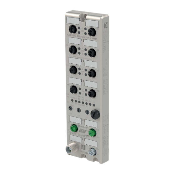
Page 9: Displays And Operating Elements
ICE1-8IOL-G60L-V1D, ICE1-8IOL-G30L-V1D Product Description QuickConnect: QuickConnect allows the modules to record the communication in an EtherNet/IP network particularly quickly through an accelerated boot-up process. This allows you to switch tools faster, for example. Displays and Operating Elements ICE1-8IOL-G30L-V1D Lnk/Act BF DIA... - Page 10 ICE1-8IOL-G60L-V1D, ICE1-8IOL-G30L-V1D Product Description Note! The LEDs in the lower area of the Ethernet IO module have different names and functions depending on the selected protocol. The following LED descriptions are therefore divided into a general part (1), which is valid for all protocol settings, and LED descriptions for a specific protocol setting (2).
- Page 11 ICE1-8IOL-G60L-V1D, ICE1-8IOL-G30L-V1D Product Description EtherNet/IP Displays E/IP areas: relevant LEDs Lnk/Act X01, Lnk/Act X02, MS, NS Function LED Lnk/Act X01 Green: connection to an Ethernet node LED Lnk/Act X02 Flashing yellow: data exchange with an IO device Off: no connection...
-
Page 12: Interfaces And Connections
ICE1-8IOL-G60L-V1D, ICE1-8IOL-G30L-V1D Product Description Interfaces and Connections The contact arrangements below show the front view of the plug-in area of the connectors. Fieldbus Connection X01, X02 Caution! Risk of destruction! Never route the power supply to the data cable. Connection: M12 socket, 4 pin, D-coded Color coding: green Figure 2.2... - Page 13 ICE1-8IOL-G60L-V1D, ICE1-8IOL-G30L-V1D Product Description Caution! Risk of destruction! Never route the power supply to the data cable. Figure 2.3 Schematic drawing of inputs/outputs 1 - 8 Port Signal Function IO-Link Class A, IO-Link sensor power supply inputs/outputs +24 V X1 ... X4...
- Page 14 ICE1-8IOL-G60L-V1D, ICE1-8IOL-G30L-V1D Product Description Caution! Loss of function when the system supply voltage is too low. Ensure in all cases that the supply voltage measured at the most remote participants (sensor/actuator) does not drop below 18 V DC in terms of system supply voltage.
-
Page 15: Dimensions
ICE1-8IOL-G60L-V1D, ICE1-8IOL-G30L-V1D Product Description Dimensions ICE1-8IOL-G60L-V1D 16.5 M12 x1 (10x) 11.5 190.3 191.8 Figure 2.6 ICE1-8IOL-G30L-V1D 14.5 M12 x1 (8x) 13.5 215.7 Figure 2.7... -
Page 16: Installation
ICE1-8IOL-G60L-V1D, ICE1-8IOL-G30L-V1D Installation Installation General Information Install the module with two M6x25/30 size screws on a level surface. The required torque is 1 Nm. Use washers according to DIN 125. For the installation holes, use a spacing of 237.3 mm to 239.7 mm. -
Page 17: Commissioning, Protocol Setting
ICE1-8IOL-G60L-V1D, ICE1-8IOL-G30L-V1D Commissioning, Protocol Setting Commissioning, Protocol Setting Setting Protocols Multiprotocol You can use the multiprotocol modules to select various protocols for communication within a fieldbus system. This allows you to integrate the multiprotocol modules into different networks without having to obtain a specific module for each protocol. This technology also allows you to use the same module in different environments. - Page 18 When restoring the factory settings, ensure that the module is connected to the power supply and switched on for at least 10 seconds. If it has been on for less than 10 seconds, the operating system may be destroyed. The module then has to be sent to Pepperl+Fuchs for repair.
-
Page 19: Commissioning For Ethernet/Ip
ICE1-8IOL-G60L-V1D, ICE1-8IOL-G30L-V1D Commissioning for EtherNet/IP Commissioning for EtherNet/IP Preparation To configure a module in the controller, you need an EDS file. Downloading the EDS File You can find the relevant EDS file in the Software section of the product detail page for the device. -
Page 20: Configuration Example
3. Select the "New Module" menu item. The following selection window opens: 4. On the right-hand side in "Module Type Vendor Filters," select the option "Pepperl + Fuchs" to view all installed modules from Pepperl+Fuchs. 5. Select the module you want to add and click the "Create" button. - Page 21 ICE1-8IOL-G60L-V1D, ICE1-8IOL-G30L-V1D Commissioning for EtherNet/IP 6. Enter a name for the module and the correct IP address. The name "IOLink_Master" and IP address "192.168.1.9" have been used in this example. 7. Click the "Change" button and change the module revision and the electronic keying settings, as well as the type of connection.
- Page 22 ICE1-8IOL-G60L-V1D, ICE1-8IOL-G30L-V1D Commissioning for EtherNet/IP 9. In the "Connection" tab of "Module Properties," you will see the selected connection type. You can also set the "Requested Packet Interval (RPI)" and "Input Type" on this tab. The minimum value for the RPI parameter is 5 ms.
-
Page 23: Io-Link Master Parameters
ICE1-8IOL-G60L-V1D, ICE1-8IOL-G30L-V1D Commissioning for EtherNet/IP IO-Link Master Parameters The parameters must be transferred to the IO-Link master after switching on. The parameters also include the IO-Link port mode. The IO-Link port data length is selected from the various available connections. - Page 24 ICE1-8IOL-G60L-V1D, ICE1-8IOL-G30L-V1D Commissioning for EtherNet/IP Function 0 = U supply diagnosis enabled 1 = U supply diagnosis disabled 0 = Reserved; do not use 0 = Reserved; do not use Table 5.2 Bold = default setting Parameter 3: global diagnostic parameters...
- Page 25 ICE1-8IOL-G60L-V1D, ICE1-8IOL-G30L-V1D Commissioning for EtherNet/IP Parameter Description Function Fail-safe value 0 = Set low DO mode port 3 1 = Set high Channel A 2 = Hold last 0 = Reserved; do not use Fail-safe value 0 = Set low...
- Page 26 ICE1-8IOL-G60L-V1D, ICE1-8IOL-G30L-V1D Commissioning for EtherNet/IP Parameters 24 - 27: Surveillance Timeout Parameters The separate auxiliary voltage, U , available on type-B IO-Link channels (channel B/pin 2), ports 5 - 8, can also be configured as an additional digital output. This enables you to switch the power supply like a digital output.
- Page 27 ICE1-8IOL-G60L-V1D, ICE1-8IOL-G30L-V1D Commissioning for EtherNet/IP Parameters 28 - 29: Digital Input Logic The standard input logic is defined as NO (normally open). It can be changed to NC (normally closed). If it is set to normally-closed, a logical 1 is transmitted to the EtherNet/IP scanner for a physically low level at the digital input port.
- Page 28 ICE1-8IOL-G60L-V1D, ICE1-8IOL-G30L-V1D Commissioning for EtherNet/IP Parameters 30 - 37: Digital IO Mode, Channel B These parameters can be used to select the function for connections 5 - 8 (IO-Link type B) of channel B. Parameter Description Function Digital IO mode...
- Page 29 ICE1-8IOL-G60L-V1D, ICE1-8IOL-G30L-V1D Commissioning for EtherNet/IP Parameters 53 - 60: IO-Link Port Mode, Channel A This parameter can be used to select the function of the IO-Link port at channel A. The following modes are available: Inactive This mode should be selected when the channel is not used. In this case, the power supply L+ to pin 1 of the port is disabled.
- Page 30 ICE1-8IOL-G60L-V1D, ICE1-8IOL-G30L-V1D Commissioning for EtherNet/IP Parameter Description Function Digital IO mode 0 = inactive Port 4 1 = DI Channel A 2 = DO 3 = SIO 4 = IO-Link 0 = Reserved; do not use Digital IO mode 0 = inactive...
- Page 31 ICE1-8IOL-G60L-V1D, ICE1-8IOL-G30L-V1D Commissioning for EtherNet/IP Parameter Description Function 132-140 IO-Link port 8 See table below Parameter Table 5.9 Bold = default setting Parameter Description Function Parameter memory 0 = Disabled Port 1 1 = Download (master to device) 2 = Upload (device to master) 3 = Download &...
- Page 32 ICE1-8IOL-G60L-V1D, ICE1-8IOL-G30L-V1D Commissioning for EtherNet/IP IO-Link Parameter Memory The parameter server of the IO-Link master can be parameterized on the "Parameter Memory" tab. The "parameter memory" function manages the IO-Link device parameters to enable the simple replacement of a device or master.
- Page 33 ICE1-8IOL-G60L-V1D, ICE1-8IOL-G30L-V1D Commissioning for EtherNet/IP Disabled and Cleared: The data storage function is disabled and the stored parameter sets are deleted. Note! The IO-Link device sets the "DS_UPLOAD_REQ Flag" flag independently if parameters have been written in block mode. IO-Link Device Validation With IO-Link device validation (IO-Link device identification), you can check the connected devices with regard to the values set in the control program, e.g., to identify correctly...
-
Page 34: Connections And Assembly Object
ICE1-8IOL-G60L-V1D, ICE1-8IOL-G30L-V1D Commissioning for EtherNet/IP Fail-Safe Behavior (for Outputs Only) This option only applies to IO-Link channels in COM mode, in which output data is used. In COM mode, IO-Link data is exchanged between the IO-Link master and the IO-Link device via serial communication. - Page 35 ICE1-8IOL-G60L-V1D, ICE1-8IOL-G30L-V1D Commissioning for EtherNet/IP "Exclusive Owner" Connection "Exclusive Owner" connections can be configured as multicast or point-to-point connections in the target to source direction. Size of input data The volume of the provider data (input data) is variable and depends on the connection number selected.
- Page 36 ICE1-8IOL-G60L-V1D, ICE1-8IOL-G30L-V1D Commissioning for EtherNet/IP Input CONN No. Assembly-ID Input Data Output Assembly-ID IO-Link master status data + 32 bytes per 108 (32 bytes IO-Link) port for IO-Link + extended IO-Link status + IO-Link events Table 5.11 Size of Output Data The size of the consumption data (output data) is variable.
-
Page 37: Bit Assignment
ICE1-8IOL-G60L-V1D, ICE1-8IOL-G30L-V1D Commissioning for EtherNet/IP "Listen Only" Connection "Listen Only" connections are available in both directions. The following EtherNet/IP assembly pairs are available for the configuration of input data: (connection = CONN, assembly = ASSY) Input CONN No. Assembly-ID Input Data... - Page 38 ICE1-8IOL-G60L-V1D, ICE1-8IOL-G30L-V1D Commissioning for EtherNet/IP Status of the Digital Inputs (Mapping Mode 1, Default) If mapping mode 1 has been selected in the device configuration, the digital input data of the module is transferred as follows. Byte 0 Digital input status of connections 1 - 4...
- Page 39 ICE1-8IOL-G60L-V1D, ICE1-8IOL-G30L-V1D Commissioning for EtherNet/IP Status of the IO-Link Process Data Validity "IOL-PD Valid" indicates whether the IO-Link process data of the corresponding connection is valid. Byte 3 IOL-PD valid Connection Channel Status of Module Diagnosis This data provides the information collected from the available module diagnosis.
-
Page 40: Io-Link Device Input Data
ICE1-8IOL-G60L-V1D, ICE1-8IOL-G30L-V1D Commissioning for EtherNet/IP This includes: CE-X1A ... CE-X8A: Channel error, channel A (pin 4) of connections X1 to X8 CE-X5B ... CE-X8B: Channel error, channel B (pin 2) of connections X1 to X8 Status of Module Diagnosis For each connection, this data provides information about whether an IO-Link device has sent an error, warning, or notification. - Page 41 ICE1-8IOL-G60L-V1D, ICE1-8IOL-G30L-V1D Commissioning for EtherNet/IP IO-Link data, 4 bytes of input data, assembly 103 Assembly 103 provides 4 bytes of IO-Link input data for each IO-Link connection with the following mapping: Input Connection Description Bytes 14 - 17 Byte 0 - byte 3 of the IO-Link input data...
-
Page 42: Io-Link Input & Extended Io-Link Status Data
ICE1-8IOL-G60L-V1D, ICE1-8IOL-G30L-V1D Commissioning for EtherNet/IP IO-Link data, 32 bytes of input data, assembly 109 Assembly 109 provides 32 bytes of IO-Link input data for each IO-Link connection with the following mapping: Input Connection Description Bytes 14 - 45 Byte 0 - byte 31 of the IO-Link input data... - Page 43 ICE1-8IOL-G60L-V1D, ICE1-8IOL-G30L-V1D Commissioning for EtherNet/IP Byte Description Vendor ID (LSB) Vendor ID (MSB) Device ID (LSB) Device ID Device ID (MSB) Reserved IO-Link, 4 bytes of input data & extended status, assembly 111 For each IO-Link connection, assembly 111 offers 4 bytes of IO-Link input data and 8 bytes of...
- Page 44 ICE1-8IOL-G60L-V1D, ICE1-8IOL-G30L-V1D Commissioning for EtherNet/IP Input Connection Description Bytes 78 - 85 Byte 0 - byte 7 of the IO-Link input data Bytes 86 - 96 Byte 0 - byte 7 of the extended IO-Link status Bytes 94 - 101...
-
Page 45: Io-Link Input Data & Extended Io-Link Status Data & Io-Link Event Data
ICE1-8IOL-G60L-V1D, ICE1-8IOL-G30L-V1D Commissioning for EtherNet/IP Input Connection Description Bytes 94 - 125 Byte 0 - byte 31 of the IO-Link input data Bytes 126 - 133 Byte 0 - byte 7 of the extended IO-Link status Bytes 134 - 165... - Page 46 ICE1-8IOL-G60L-V1D, ICE1-8IOL-G30L-V1D Commissioning for EtherNet/IP This data set can contain up to three event messages for the connected IO-Link device. Event 1 always displays the last event messages; earlier event messages are moved to event block two or three. The event data is only deleted after the IO-Link master has been restarted.
- Page 47 ICE1-8IOL-G60L-V1D, ICE1-8IOL-G30L-V1D Commissioning for EtherNet/IP IO-Link, 4 bytes of input & extended status & event data, assembly 119 For each IO-Link connection, assembly 119 offers 4 bytes of IO-Link input data, 8 bytes of extended IO-Link status data, and 12 bytes of IO-Link event data with the following mapping:...
- Page 48 ICE1-8IOL-G60L-V1D, ICE1-8IOL-G30L-V1D Commissioning for EtherNet/IP Input Connection Description Bytes 78 - 85 Byte 0 - byte 7 of the extended IO-Link status Bytes 86 - 97 Byte 0 - byte 11 of the IO-Link event data Bytes 98 - 105...
- Page 49 ICE1-8IOL-G60L-V1D, ICE1-8IOL-G30L-V1D Commissioning for EtherNet/IP Input Connection Description Bytes 218 - 229 Byte 0 - byte 11 of the IO-Link event data Bytes 230 - 245 Byte 0 - byte 15 of the IO-Link input data Bytes 246 - 253...
-
Page 50: Control Data Of The Io-Link Master (Outputs)
ICE1-8IOL-G60L-V1D, ICE1-8IOL-G30L-V1D Commissioning for EtherNet/IP 5.5.5 Control Data of the IO-Link Master (Outputs) The following EtherNet/IP consumption modules are available for the configuration of output data: Assembly Description 4 bytes of IO-Link master control data (without IO-Link device output data) -
Page 51: Control Data Of The Io-Link Device (Outputs)
ICE1-8IOL-G60L-V1D, ICE1-8IOL-G30L-V1D Commissioning for EtherNet/IP Byte 1 Control of digital outputs, channel B of connections 1 - 8 Connection Channel Control of IO-Link COM Mode This mode can be used temporarily as long as the corresponding COM control bit is set. It switches one or more IO-Link connections previously configured as "IOL SIO"... - Page 52 ICE1-8IOL-G60L-V1D, ICE1-8IOL-G30L-V1D Commissioning for EtherNet/IP IO-Link device, 8 bytes of output data, assembly 104 Assembly 104 provides 8 bytes of IO-Link output data (master to device) for each IO-Link connection with the following mapping: Input Connection Description Bytes 4 - 11...
-
Page 53: Ethernet/Ip Objects
ICE1-8IOL-G60L-V1D, ICE1-8IOL-G30L-V1D Commissioning for EtherNet/IP EtherNet/IP Objects The following EtherNet/IP objects are supported by the device: Identity object (class code 0x01) Assembly object (class code 0x04) Connection manager object (class code 0x06) EtherNet/IP link object (class code 0xF6) TCP/IP object (class code 0xF5) - Page 54 ICE1-8IOL-G60L-V1D, ICE1-8IOL-G30L-V1D Commissioning for EtherNet/IP Error Name Type Error code description code IO-Link master error UINT Service not available Connection blocked Timeout Invalid index Invalid sub-index Incorrect connection Incorrect connection function Invalid length ISDU not supported IO-Link Device Error USINT...
- Page 55 ICE1-8IOL-G60L-V1D, ICE1-8IOL-G30L-V1D Commissioning for EtherNet/IP Error Name Type Error code description code IO-Link Device Error USINT See IO-Link specification IO-Link device additional error USINT See IO-Link specification IO-Link Fail-Safe Parameter Object (Class Code 0x81) In case of a loss of EtherNet/IP communication, fail-safe values can be defined for the IO-Link device output data.
-
Page 56: Commissioning For Profinet
The configuration and commissioning process for the modules described over the following pages was performed using TIA Portal V15 project planning software from SIEMENS. The configuration is based on the example of an ICE1-8IOL-G60L-V1D module. For other module versions, configuration is carried out with a few minor changes. -
Page 57: Integration Of Profinet Io Modules In The Tia Portal
As an example, the following is an explanation of how to configure an Ethernet IO module as a Profinet type in the TIA portal, based on the ICE1-8IOL-G60L-V1D module. 1. Install the GSDML file for the desired module in the TIA Portal. - Page 58 ICE1-8IOL-G60L-V1D, ICE1-8IOL-G30L-V1D Commissioning for PROFINET Figure 6.3 Slot 1 is automatically occupied with the status/control module, which cannot be deleted. The remaining sub-slots are configured as a digital input (DI) by default and can be changed. Figure 6.4 The following sub-module profiles are available for configuration of an 8IOL module:...
- Page 59 ICE1-8IOL-G60L-V1D, ICE1-8IOL-G30L-V1D Commissioning for PROFINET Figure 6.5...
-
Page 60: Assigning A Unique Device Name In The Control System
ICE1-8IOL-G60L-V1D, ICE1-8IOL-G30L-V1D Commissioning for PROFINET 6.2.2 Assigning a Unique Device Name in the Control System PROFINET IO devices are addressed in the PROFINET network via a unique device name. This can be freely assigned by the user but may only appear once in the network. -
Page 61: Assigning The Device Name To A Profinet Io Module
ICE1-8IOL-G60L-V1D, ICE1-8IOL-G30L-V1D Commissioning for PROFINET 6.2.3 Assigning the Device Name to a PROFINET IO Module So that each node in the PROFINET network can be assigned an IP address, each module must have a device name. A participant search displays the PROFINET devices which have been found. - Page 62 ICE1-8IOL-G60L-V1D, ICE1-8IOL-G30L-V1D Commissioning for PROFINET Figure 6.9 4. Select a module from those found. If the desired module is not displayed in the list of available nodes on the network, you can change the device filter and refresh the list. If the device still does not appear, please check your firewall settings.
-
Page 63: Configuring The Io-Link Channels
ICE1-8IOL-G60L-V1D, ICE1-8IOL-G30L-V1D Commissioning for PROFINET Figure 6.10 If the device name was set successfully, this will be indicated by the status. 6. Complete the process by pressing the "Assign Name" button. 6.2.4 Configuring the IO-Link Channels A preconfiguration of the I/O function is automatically used for slot 1 of the rack. - Page 64 ICE1-8IOL-G60L-V1D, ICE1-8IOL-G30L-V1D Commissioning for PROFINET Figure 6.11 2. Right-click this entry. The following menu appears: Figure 6.12 3. Select the "Delete" option. Click "Yes" to confirm the following dialog box.
- Page 65 ICE1-8IOL-G60L-V1D, ICE1-8IOL-G30L-V1D Commissioning for PROFINET Figure 6.13 Creating an IO-Link Channel Configuration 1. Different IO-Link communication channels (input channel, output channel or input/output channel) are available in addition to the digital input and output channels. Click the corre- sponding folder in the hardware catalog to view a selection of options:...
- Page 66 ICE1-8IOL-G60L-V1D, ICE1-8IOL-G30L-V1D Commissioning for PROFINET 2. Select the desired option and then click and hold the left mouse button to drag the configuration to a free IO-Link sub-slot.
-
Page 67: Parameterization Of The Io-Link Channels
ICE1-8IOL-G60L-V1D, ICE1-8IOL-G30L-V1D Commissioning for PROFINET The following options are available for the IO-Link C/Q channel (channel A/pin 4): Digital Input: In this mode the channel works as a digital input. The IO-Link master does not attempt to independently establish communication with the connected IO-Link device. - Page 68 ICE1-8IOL-G60L-V1D, ICE1-8IOL-G30L-V1D Commissioning for PROFINET Figure 6.14 IOL Parameter Storage The parameter server of the IO-Link master can be parameterized in the "IOL Parameter Storage" section. The "parameter memory" function manages the IO-Link device parameters to enable the simple replacement of a device or master.
- Page 69 ICE1-8IOL-G60L-V1D, ICE1-8IOL-G30L-V1D Commissioning for PROFINET Upload only (device to master): Activates the function to upload the IO-Link device parameter data to the IO-Link master. An upload is executed automatically when an IO-Link device is connected and the master has no valid data. This is the case if the mode Disabled and Cleared has previously been configured, or in Disabled mode, as per the default settings.
- Page 70 ICE1-8IOL-G60L-V1D, ICE1-8IOL-G30L-V1D Commissioning for PROFINET No validation: This option is the default setting. In this case, neither the vendor ID, the device ID nor the serial number are synchronized between the IO-Link device and entered IO-Link master data after switching on and before communication is started.
-
Page 71: Parameterization Of The Status/Control Module
ICE1-8IOL-G60L-V1D, ICE1-8IOL-G30L-V1D Commissioning for PROFINET Set High: All bits of output data with a value of 1 are transferred to the IO-Link device. Hold Last: The last valid output value received by the control unit is continuously and cyclically transferred to the IO-Link device. - Page 72 ICE1-8IOL-G60L-V1D, ICE1-8IOL-G30L-V1D Commissioning for PROFINET Figure 6.18 You can now carry out the desired parameter settings in the dialog (4). The following is a brief description of the individual areas for parameter setting. General Device Settings Digital-IO Bit Mapping Mode Using the "Digital-IO Bit Mapping Mode"...
- Page 73 ICE1-8IOL-G60L-V1D, ICE1-8IOL-G30L-V1D Commissioning for PROFINET General Diagnosis Settings Figure 6.19 In the "General Diagnosis Settings" area, you can enable or disable diagnosis and diagnostic stages such as alarm signals for events. Note! "Report U Supply Voltage Error" is disabled in the default setting to prevent diagnostic messages if the supply voltage is switched on or off later.
- Page 74 ICE1-8IOL-G60L-V1D, ICE1-8IOL-G30L-V1D Commissioning for PROFINET Figure 6.20 Surveillance Timeout Configuration You can also configure the separate auxiliary voltage U that is available on type B IO-Link channels (channel B/pin2) of ports 5 - 8 as an additional digital output ("Digital IO Mode for Ch.
- Page 75 ICE1-8IOL-G60L-V1D, ICE1-8IOL-G30L-V1D Commissioning for PROFINET NC (normally closed): In this case, an undamped sensor has a closed switch output (high signal). The device input detects a high level, inverts the signal, and returns a 0 to the control unit. Figure 6.22 Digital-IO-mode for Ch.
-
Page 76: Siemens Io-Link Library
ICE1-8IOL-G60L-V1D, ICE1-8IOL-G30L-V1D Commissioning for PROFINET Digital Output (DO): In this mode, pin 2 of the IO-Link connections of class B ports 5 - 8 can be used as a digital output. The control bits are transferred to the device by the control unit within the status/control module. -
Page 77: Replacing Devices Without A Removable Medium/Programming Unit
ICE1-8IOL-G60L-V1D, ICE1-8IOL-G30L-V1D Commissioning for PROFINET Note! If the logical input address for the IO_LINK_CALL module is used, it may be necessary for the input address to be less than or equal to the output address. You may need to change this value manually in the engineering tool. - Page 78 ICE1-8IOL-G60L-V1D, ICE1-8IOL-G30L-V1D Commissioning for PROFINET 4. Define the network topology for the device replacement. To do so, select "Devices & networks" and "Topology view." 5. Use the mouse to drag a connection between the module and the PLC. Figure 6.27...
-
Page 79: Identification And Maintenance Functions (I&M)
ICE1-8IOL-G60L-V1D, ICE1-8IOL-G30L-V1D Commissioning for PROFINET The port interconnection was successful if the link is shown in the "Topology View" and on the "Partner Port." 6.2.9 Identification and Maintenance Functions (I&M) The PROFINET module is capable of uniquely identifying devices installed in the system by means of an electronic nameplate. - Page 80 ICE1-8IOL-G60L-V1D, ICE1-8IOL-G30L-V1D Commissioning for PROFINET I&M 2 Length Data object [byte] Access Default value/description INSTALLATION_DATE Read/w 0x20 et seq. (empty) rite The supported data format is a visible character string with a fixed length of 16 bytes; "YYYY-MM-DD hh:mm" or "YYYY- MM-DD"...
- Page 81 ICE1-8IOL-G60L-V1D, ICE1-8IOL-G30L-V1D Commissioning for PROFINET I&M 99 Length Data object [byte] Access Default value/description IOL_VERSION Read 0x11 (IO-Link version 1.1) IOL_PROFILE_VERSION Read 0x10 (IO-Link profile version 1.0) IOL_FEATURE_SUPPORT Read 0x00000000 NUMBER_OF_PORTS Read 0x08 (number of supported IO-Link connections) REF_PORT_CONFIG Read...
-
Page 82: Prioritized Start-Up/Fast Start-Up (Fsu)
ICE1-8IOL-G60L-V1D, ICE1-8IOL-G30L-V1D Commissioning for PROFINET Length Data Data object [byte] Type Coding Description BlockType Word I&M 0: 0x0020 BlockHeader I&M 1: 0x0021 I&M 2: 0x0022 I&M 3: 0x0023 I&M 4: 0x0024 I&M 16...23: 0x0F00 I&M 99: 0x0F00 BlockLength Word I&M 0: 0x0038 I&M 1: 0x0038... - Page 83 ICE1-8IOL-G60L-V1D, ICE1-8IOL-G30L-V1D Commissioning for PROFINET Figure 6.29 1. Select "Device View" (1) and the desired module (in this example, slot 1 for ICE1-8IOL- G60L-V1D_1). 2. Then, in the "General" tab, select the "Advanced Options" area (2). 3. Click on the "Prioritized Start-Up" option (3) to enable prioritized startup.
-
Page 84: Resetting Modules To Their Factory Settings
ICE1-8IOL-G60L-V1D, ICE1-8IOL-G30L-V1D Commissioning for PROFINET 6.2.11 Resetting Modules to their Factory Settings To reset the modules to the factory settings, you must search for accessible PROFINET nodes in the TIA Portal. 1. Open the dialog "Accessible devices" via the main menu "Online -> Accessible devices .."... -
Page 85: Bit Assignment
ICE1-8IOL-G60L-V1D, ICE1-8IOL-G30L-V1D Commissioning for PROFINET Figure 6.31 3. Initiate the reset process by pressing the "Reset" button and then confirming the safety prompt. Figure 6.32 Bit Assignment The IO-Link master uses a modular device model. Slot 1/sub-slot 1 contains the status/control module. - Page 86 ICE1-8IOL-G60L-V1D, ICE1-8IOL-G30L-V1D Commissioning for PROFINET Process Data Status/Control Module, Slot 1/Sub-slot 1 Digital IO Mapping Mode 1 (Default Mapping) If mapping mode 1 has been selected in the device configuration, the data of the status/control module is transferred as follows.
- Page 87 ICE1-8IOL-G60L-V1D, ICE1-8IOL-G30L-V1D Commissioning for PROFINET Output data of the status/control module Byte Byte 0, digital output status Connection X4 Channel Table 6.14 Byte 0, digital output status Byte Byte 1, digital output status Connection Channel Table 6.15 Byte 1, digital output status...
- Page 88 ICE1-8IOL-G60L-V1D, ICE1-8IOL-G30L-V1D Commissioning for PROFINET Digital IO Mapping Mode 2 (Alternative Mapping) If mapping mode 2 has been selected in the device configuration, the data of the status/control module is transferred as follows. Input data of the status/control module Byte...
- Page 89 ICE1-8IOL-G60L-V1D, ICE1-8IOL-G30L-V1D Commissioning for PROFINET Output data of the status/control module Byte Byte 0, digital output status Connection X8 Channel Table 6.22 Byte 0, digital output status Byte Byte 1, digital output status Connection Channel Table 6.23 Byte 1, digital output status...
- Page 90 ICE1-8IOL-G60L-V1D, ICE1-8IOL-G30L-V1D Commissioning for PROFINET IO-Link Connections Process Data, Slot 1/Sub-Slot 2 - Sub-Slot 9 The process data lengths of the IO-Link connections in COM mode depend on the configurations of IO-Link connections X1 - X8. Data lengths of 1 - 32 bytes of input data and/or 1 - 32 bytes of output data are configurable.
-
Page 91: The Integrated Web Server
ICE1-8IOL-G60L-V1D, ICE1-8IOL-G30L-V1D The Integrated Web Server The Integrated Web Server The module has an integrated web server that provides functions for configuring the module and displaying status and diagnostic information. With the help of a standard web browser, you can access the available functions via an existing TCP/IP connection. To use the web server, the module must have its own IP address. - Page 92 ICE1-8IOL-G60L-V1D, ICE1-8IOL-G30L-V1D The Integrated Web Server Device Overview The left side shows a graphical representation of the module with all LEDs and the positions of the rotary coding switches Device Information The "Device Information" table contains some basic data on the module, e.g., the variant, the state of the cyclic communication and a diagnostic indicator.
- Page 93 ICE1-8IOL-G60L-V1D, ICE1-8IOL-G30L-V1D The Integrated Web Server In offline mode, you can configure the port mode via the wrench icon. The following modes are available when doing so: Inactive Digital Input Digital Output IO-Link SIO IO-Link If "Force Mode" is activated via the web server in offline mode, it is not possible to connect to a controller.
- Page 94 ICE1-8IOL-G60L-V1D, ICE1-8IOL-G30L-V1D The Integrated Web Server Port diagnosis shows incoming and outgoing diagnoses in plain text. Pin 2 and pin 4 contain information about the configuration and status of the port. Additional information about the connected sensor and its process data is shown under IO-Link Ports.
- Page 95 ICE1-8IOL-G60L-V1D, ICE1-8IOL-G30L-V1D The Integrated Web Server Network parameters (IP Settings): • IP address, readable and writable • Subnet mask, readable and writable • Gateway address, readable and writable Clicking on the "Submit" button transfers the new parameters to the module. The new settings take effect on the module once the power supply has been restored.
- Page 96 Click on the "Contact" tab in the menu bar of the start window. A new window with the contact data of Pepperl+Fuchs opens: Figure 7.5 The address of the contact page is: http://[IP address]/contact.htm This page provides information about Pepperl+Fuchs Gmbh contact data.
-
Page 97: Troubleshooting
ICE1-8IOL-G60L-V1D, ICE1-8IOL-G30L-V1D Troubleshooting Troubleshooting Diagnostics Indicator in the Integrated Web Server The module shows the error diagnostics on the connection page of the integrated web server. For information on how to call up the connection page, see chapter 7. Figure 8.1 Diagnostic data is displayed in the "Port Diagnosis"... - Page 98 ICE1-8IOL-G60L-V1D, ICE1-8IOL-G30L-V1D Troubleshooting Cause OB call Diagnostics alarm (short circuit, overload, wire break, low voltage on an I/O OB82 module) Failure of a station or a rack OB86 The initial information regarding the cause and type of fault is provided by the OB called and its start information.
-
Page 99: Alarm Signals And Error Messages Via Ethernet Ip
ICE1-8IOL-G60L-V1D, ICE1-8IOL-G30L-V1D Troubleshooting Display of diagnosis in the TIA Portal 1. Select the faulty I/O module in the hardware manager and navigate to its device view. 2. Select the affected channel/the submodule. 3. Open the online diagnostics by right-clicking with the mouse and select the menu item "Online &... - Page 100 ICE1-8IOL-G60L-V1D, ICE1-8IOL-G30L-V1D Troubleshooting MI-LVA: Module information—low-voltage auxiliary power supply MI-LVS: Module information—low-voltage system/sensor power supply Error in the Auxiliary Voltage/Actuator Power Supply The voltage value of the power supply for the auxiliary voltage/actuator power supply is monitored globally. If the U diagnostic messaging is enabled, an error message is generated as soon as the voltage falls below approx.
- Page 101 ICE1-8IOL-G60L-V1D, ICE1-8IOL-G30L-V1D Troubleshooting SCS-X1 ... SCS-X8: Sensor short circuit at connections X1 to X8 Overload/Short Circuit of the Digital 500 mA Outputs The digital outputs at the C/Q pin are protected against short circuit and overload. In case of a fault, the output is switched off automatically and cyclically switched on again automatically.
- Page 102 ICE1-8IOL-G60L-V1D, ICE1-8IOL-G30L-V1D Troubleshooting MI-VAL: Module information—IO-Link validation error MI-SCB: Module information—actuator short circuit, channel B MI-SCA: Module information—actuator short circuit, channel A MI-SCS: Module information—sensor short circuit MI-LVA: Module information—low-voltage auxiliary power supply MI-LVS: Module information—low-voltage system/sensor power supply CE-X5B ... CE-X8B: Channel error, channel B (pin 2) of connections X1 to X8...
- Page 103 ICE1-8IOL-G60L-V1D, ICE1-8IOL-G30L-V1D Troubleshooting MI-LVS: Module information—low-voltage system/sensor power supply CE-X1A ... CE-X8A: Channel error, channel A (pin 4) of connections X1 to X8 IO-Link Validation Error If an IO-Link device is removed in COM mode and the validation is parameterized, or a validation error is detected, e.g., due to an incorrect vendor ID or device ID, the following...
- Page 104 ICE1-8IOL-G60L-V1D, ICE1-8IOL-G30L-V1D Troubleshooting DN-X1A ... DN-X8A: IO-Link device notification, channel A (pin 4, C/Q) of connections X1 to X8 VAL-X1A ... VAL-X8A: IO-Link master validation error, channel A (pin 4, C/Q) of connections X1 to X8 IO-Link Device Warning In the event that a device sends a warning to the master, the following diagnostic bits can be set...
- Page 105 Twinsburg, Ohio 44087 · USA Tel. +1 330 4253555 E-mail: sales@us.pepperl-fuchs.com Asia Pacific Headquarters Pepperl+Fuchs Pte Ltd. Company Registration No. 199003130E Singapore 139942 Tel. +65 67799091 E-mail: sales@sg.pepperl-fuchs.com www.pepperl-fuchs.com Subject to modifications / DOCT-5792B Copyright PEPPERL+FUCHS • Printed in Germany 02/2019...
Need help?
Do you have a question about the ICE1-8IOL-G60L-V1D and is the answer not in the manual?
Questions and answers