
Related Manuals for Pepperl+Fuchs IC-KP2-2HB6-V15B


Summary of Contents for Pepperl+Fuchs IC-KP2-2HB6-V15B
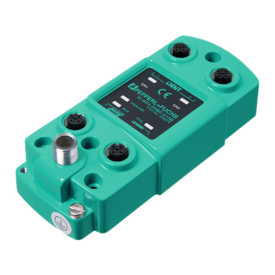
- Page 1 FACTORY AUTOMATION MANUAL IC-KP2-2HB6-V15B IDENTControl Compact unit with interface for PROFIBUS DP...
- Page 2 IC-KP2-2HB6-V15B With regard to the supply of products, the current issue of the following document is applicable: The General Terms of Delivery for Products and Services of the Electrical Industry, published by the Central Association of the Electrical Industry (Zentralverband Elektrotechnik und Elektroindustrie (ZVEI) e.V.) in its most recent version as well as the supplementary clause: "Expanded reservation...
- Page 3 IC-KP2-2HB6-V15B Contents 1 Introduction................. 5 2 Declaration of conformity ..........6 CE conformity ....................6 3 Safety................... 7 Symbols relevant to safety ................7 Intended use ....................7 General notes on safety.................7 Contact protection..................8 4 Product Description ............9 Product family ....................9 4.1.1 R/W heads ....................9 4.1.2 Read Only Tags/Read/Write Tags .............9...
- Page 4 IC-KP2-2HB6-V15B Contents 6 Commissioning ..............23 Preliminary considerations ................. 23 Connection....................24 Device settings ................... 24 Address setting ..................25 7 Commands................ 27 Communication via the RS 232 diagnostic interface ........27 7.1.1 Commands for the RS 232 diagnostic interface ........27 7.1.2 Legend ....................
-
Page 5: Handling Instructions
Introduction Introduction Congratulations You have chosen a device manufactured by Pepperl+Fuchs. Pepperl+Fuchs develops, produces and distributes electronic sensors and interface modules for the market of automation technology on a worldwide scale. Before you install this device and put it into operation, please read the operating instructions thoroughly. -
Page 6: Declaration Of Conformity
IC-KP2-2HB6-V15B Declaration of conformity Declaration of conformity CE conformity This product was developed and manufactured under observance of the applicable European standards and guidelines. Note! A declaration of conformity can be requested from the manufacturer. -
Page 7: Symbols Relevant To Safety
In case of ignoring the devices and any connected facilities or systems may be interrupted or fail completely. Intended use The IDENTControl Compact IC-KP2-2HB6-V15B is a control unit with integral PROFIBUS interface designed for identification systems. The IDENTControl Compact can be used as a control cabinet module or for field applications. -
Page 8: Contact Protection
IC-KP2-2HB6-V15B Safety Store the not used device in the original packaging. This offers the device optimal protection against impact and moisture. Ensure that the ambient conditions comply with regulations. Note! Disposal Electronic waste is hazardous waste. When disposing of the equipment, observe the current statutory requirements in the respective country of use, as well as local regulations. -
Page 9: Product Description
Read/write tags in this frequency range save larger quantities of data and offer a considerably higher reading speed than read/write tags of the 125 kHz system. IQH-* and IQH1-* read/write heads from Pepperl+Fuchs are compatible with most existing read/write tags that comply with standard ISO 15693. With the IQH2-* read/write heads you can use read/write tags that comply with standard ISO 14443A. - Page 10 IC-KP2-2HB6-V15B Product Description Data carrier 868 MHz (UHF) Data carriers in this frequency range can be passive as well as active (with battery) and use a specially-shaped rod antenna as the resonance element. The passive transponders can be produced very cheaply and have a range of several meters.
-
Page 11: Connection Accessories
IC-KP2-2HB6-V15B Product Description Connection accessories 4.2.1 Connection cable for R/W heads and trigger sensors Compatible connection cables with shielding are available for connecting the R/W heads and trigger sensors. Figure 4.2 Accessories Description 2 m long (straight female, angled male) - Page 12 IC-KP2-2HB6-V15B Product Description 4.2.2 Cable connectors for the power supply Compatible M12 sockets with an open cable end for connecting the IDENTControl Compact to a power supply are available in different lengths. Figure 4.3 Accessories Model number Length 2 m (straight socket)
-
Page 13: Delivery Package
IC-KP2-2HB6-V15B Product Description Note! The T-distributor is designed for general applications in the PROFIBUS network and is not compatible with the IDENTControl Compact. Always use the Y cable with the IDENTControl Compact. 4.2.4 Adapter for RS 232 diagnostic interface A compatible adapter is available for connecting the IDENTControl Compact to the RS 232 diagnostic interface. -
Page 14: Device Characteristics
Alternatively, 1 R/W head and 1 trigger sensor can be connected ■ LED status indicators for bus communication and R/W heads ■ Interfaces and connections The control unit IC-KP2-2HB6-V15B has the following interfaces and connections: socket at housing read/write head trigger sensor... -
Page 15: Displays And Controls
IC-KP2-2HB6-V15B Product Description Displays and controls BUS Address (High Nibble) BUS Address (Low Nibble) PWR/ERR Diag LEDs Description Function Status description Status display for LED lights up green when there is an active R/W heads command on the R/W head. -
Page 16: Installation
■ Retain the original packaging in case you have to store or ship the device again at a later date. Should you have any questions, please contact Pepperl+Fuchs. EMC concept The outstanding noise immunity of the IDENTControl Compact against emission and immission is based on its consistent shielding design, which uses the principle of the Faraday cage. -
Page 17: Device Connection
IC-KP2-2HB6-V15B Installation You must establish a low resistance and low inductance connection between the shields and ground so that the shielding is not interrupted through the metal enclosure. The complete electronics system and all routed cables are therefore located within a Faraday cage. -
Page 18: Ground Connection
IC-KP2-2HB6-V15B Installation trigger switch signal For details of compatible read/write heads, see chapter 4.1.1 and of compatible connecting cables, see chapter 4.2.1. Connecting read/write heads Connect the read/write heads or the trigger sensor with compatible connecting cable to the top of the housing via the M12 connector. - Page 19 IC-KP2-2HB6-V15B Installation 5.4.4 Connecting the RS 232 diagnostic interface Use the adapter V1S-G-0.15M-PUR-SUBD to connect the IDENTControl Compact to the RS 232 diagnostic interface. Connection diagram of the adapter for the RS 232 diagnostic interface n.c. n.c. 6 ... 9 n.c.
- Page 20 IC-KP2-2HB6-V15B Installation 5.4.6 Cables The bus line is specified in EN 50170 as line type A. It can be used in accordance with the following table. The line parameters and lengths for line type B are also specified in the two following tables. When planning a new plant, only line type A should be used because of the higher total line length.
- Page 21 IC-KP2-2HB6-V15B Installation 5.4.8 Terminator With the PROFIBUS DP, every bus segment must be terminated on both line ends with terminating resistors. For compatible connection accessories see chapter 4.2. Note! The ICZ-TR-V15B terminator cannot be used together with the Y cable ICZ-3T- 0,3M-PUR ABG-V15B-G because the voltage required by the terminator cannot be supplied.
- Page 22 IC-KP2-2HB6-V15B Installation Dimensions of the ICZ-2T/TR-0,2M-PUR ABG-V15B-G ~ 280 Connection layout of the ICZ-2T/TR-0,2M-PUR ABG-V15B-G 390 Ohm PB-P 220 Ohm PB-N 390 Ohm Example: connection of adjacent devices IC-KP-B6-V15B Y connection cable ICZ-3T-0.2M-PUR ABG-V15B-G V15B-G-*M-PUR ABG-V15B-G For last node: ICZ-2T/TR-0.2M-PUR ABG-V15B-G with integrated terminator...
-
Page 23: Preliminary Considerations
IC-KP2-2HB6-V15B Commissioning Commissioning Preliminary considerations Caution! Uncontrollable triggered processes The plant where the device is installed may be damaged. Before commissioning, make sure that all processes run in a controlled manner. These instructions contain all important information required to operate the IDENTControl Compact unit with the PROFIBUS DP. -
Page 24: Device Settings
IC-KP2-2HB6-V15B Commissioning Connection Warning! Incorrect electrical connection Incorrect connections may damage the system. Before commissioning, familiarize yourself with the system of communication between your PROFIBUS DP and the read/write station. Check all connections before commissioning. When the supply voltage is connected and the device is initialized, the PWR/ERR LED lights up green. -
Page 25: Address Setting
IC-KP2-2HB6-V15B Commissioning Address setting Assign the IDENTControl Compact an address between 0 (00h) and 125 (7Dh) that is not already assigned to another node. The device address is set in the hexadecimal system. You have three options to set the device address: 1. - Page 26 IC-KP2-2HB6-V15B Commissioning Preparing the device address setting via the PROFIBUS or the RS 232 diagnostic interface If you set the rotary switches to a value between "7Eh" and "FEh", the device is allocated the address "7Eh" (126), which you can modify during operation via the PROFIBUS or the RS 232 diagnostic interface.
- Page 27 R/W head, preset handheld parameters, and the data carrier type. Any kind of terminal program can be used to control communication. We recommend RFIDControl software, which is available from Pepperl+Fuchs free of charge. The following RS 232 diagnostic interface parameters are fixed: Baud rate 38 400, 8 data bits, 1 stop bit, no parity.
- Page 28 IC-KP2-2HB6-V15B Commands 08.08.08#<CR> 0003102D IQH1-FP-V1 #204623 1831422 05.08.08#<CR> 0003202D IQH1-FP-V1 #204623 1831422 05.08.08#<CR> If a R/W head is not connected, the following second response appears. 60031000#<CR> Or the third response: 60032000#<CR>. Get state (GS) The command GS retrieves the settings.
- Page 29 IC-KP2-2HB6-V15B Commands 7.1.2 Legend <Command code> : Two-digit hexadecimal code, same as the command code transferred via the PROFIBUS <Data length> : Three-digit hexadecimal code, number of other digits included in the response (excluding end identifier) <Multiplex mode> : Multiplex mode, 0=off, 1=on <Trigger mode>...
- Page 30 IC-KP2-2HB6-V15B Commands General information on PROFIBUS DP The PROFIBUS DP is a standardized, open fieldbus, which enables data exchange between PLCs, PCs, operating and observation devices, and also sensors and actuators. For more detailed information on the PROFIBUS DP, refer to the PROFIBUS standard EN 50170 and to the current literature on the subject (e.g.
- Page 31 IC-KP2-2HB6-V15B Commands 7.2.3 PROFIBUS DP functions Function Description Master Set_Prm Transfers parameter data to a DP slave Class 1 Chk_Cfg Transfers the configuration data for testing to a DP slave Class 1 Get_Cfg Reads out the configuration data of a DP slave...
- Page 32 IC-KP2-2HB6-V15B Commands Select one of the predefined modules. In doing so, make sure that the data field size for the read/write commands used is sufficient, depending on the parameter word count. One word has 32 bits. Note! The “Data Hold Time” and the diagnostic interrupt are stored in the GSD file.
- Page 33 IC-KP2-2HB6-V15B Commands Address Length Content Byte 32 1 byte Identification byte of R/W head 2 Byte 33 3 bytes Software number of R/W head 2 Byte 36 6 bytes Software creation date of R/W head 2 42 bytes Total length of external diagnostics...
- Page 34 IC-KP2-2HB6-V15B Commands Example: One type IPH-L2 R/W head is connected. Address Length Content Byte 0 1 byte Byte 1 2 bytes 00h 00h Byte 3 1 byte Byte 4 3 bytes Byte 7 6 bytes 071108 Byte 13 9 bytes...
-
Page 35: Software Information
IC-KP2-2HB6-V15B Commands 7.3.3 Software information A command consists of the command code, a specified number of parameters, the toggle flag, and the data relating to the command. The command is entered in the output data field of the master. A response consists of the echo of the command code, a parameter, the toggle flag, the status, a reply counter, and the read data. -
Page 36: Command Types
IC-KP2-2HB6-V15B Commands If the status is FFh (command detected), the second byte of the response also corresponds to the second byte of the command call-up. In the actual response (status not FFh), the second byte contains the parameters for the response, i.e. - Page 37 IC-KP2-2HB6-V15B Commands 7.3.5 Command overview The commands in the list are described in detail on the following pages. System commands Command Abbre- code Command description viation See "Change tag (CT)" on page 39 See "Quit (QU)" on page 42 See "Configuration store (CS)" on page 43 See "Reset (RS)"...
- Page 38 IC-KP2-2HB6-V15B Commands IPC03 configuration Command Abbre- code Command description viation See "Single get configuration (SG)" on page 60 104d See "Enhanced buffered get configuration (EG)" on page 61 See "Single write configuration (SC)" on page 62 102d See "Enhanced buffered write configuration (EC)" on page 64 Extended Commands for Type IPC11 and IDC-...-1K Read/Write Tags...
- Page 39 IC-KP2-2HB6-V15B Commands 7.3.6 System commands Change tag (CT) Command: Byte Content Bit no. Byte 0 Command code (04h) Byte 1 Reserved/Ident channel/Toggle bit <Channel> <T> Byte 2 Data carrier type in ASCII <TagType> (high byte) Byte 3 Data carrier type in ASCII <TagType>...
- Page 40 IC-KP2-2HB6-V15B Commands Tag type Chip type Access Writable Read only Frequency desig- memory code length range High nation [bytes] [byte] byte byte IPC12 P+F FRAM Read/write 125 kHz read only code All ISO 15693 compliant Read/write 13.56 MHz IQC20 read/write tags...
- Page 41 The tag type configured in the read/write head as the default is selected. Read/write tags can have 4-byte (older versions) or 7-byte UIDs. IQC42 and IQC43 type read/write tags from Pepperl+Fuchs generally have 7-byte UIDs. Note! In a plant where only one tag type is used, it is advantageous to permanently configure that tag type so that the read/write head detects the tag quicker.
- Page 42 IC-KP2-2HB6-V15B Commands Quit (QU) Command: Byte Content Bit no. Byte 0 Command code (02h) Byte 1 Reserved/Ident channel/Toggle bit <Channel> <T> Byte 2 not used Byte 3 not used Byte 4 not used Byte 5 not used Byte 6 not used...
- Page 43 IC-KP2-2HB6-V15B Commands Configuration store (CS) Command: Byte Contents Bit no. Byte 2 Command code (17h) Byte 3 Reserved/Ident channel/Toggle bit <Channel> <T> Byte 4 Mode <Mode> Byte 5 not used Byte 6 not used Byte 7 not used Byte 8...
- Page 44 IC-KP2-2HB6-V15B Commands Reset (RS) Command: Byte Content Bit no. Byte 0 Command code (16h) Byte 1 Reserved/Channel/Toggle bit <T> Byte 2 not used Byte 3 not used Byte 4 not used Byte 5 not used Byte 6 not used Byte 7 not used This command terminates all active commands.
- Page 45 IC-KP2-2HB6-V15B Commands Set multiplexed mode (MM): Byte Content Bit no. Byte 0 Command code (9Bh) Byte 1 Reserved/Toggle bit <T> Byte 2 Multiplex mode <F> Byte 3 unused Byte 4 unused Byte 5 unused Byte 6 unused Byte 7 unused...
- Page 46 IC-KP2-2HB6-V15B Commands Set trigger mode (TM): Byte Contents Bit no. Byte 0 Command code (9Ch) Byte 1 Ident channel/sensor <Ident channel> <Sensor channel> <T> channel/toggle bit Byte 2 Trigger mode <Trigger mode> Byte 3 not used Byte 4 not used...
- Page 47 IC-KP2-2HB6-V15B Commands If a read/write command is sent to the triggered channel <Ident channel> when trigger mode is active, this command is always activated if the <Sensor channel> transmits status 0. <Ident channel> transmits status 0 to confirm receipt of this command.
- Page 48 IC-KP2-2HB6-V15B Commands 7.3.7 Standard read/write commands single read fixcode (SF) Command: Byte Content Bit no. Byte 0 Command code (01h) Byte 1 Reserved/Ident channel/Toggle bit <Channel> <T> Response: Byte Content Bit no. Byte 0 Command code (01h) Byte 1 Reserved/Channel/Toggle bit <Channel>...
- Page 49 IC-KP2-2HB6-V15B Commands Enhanced buffered fixcode (EF) Command: Byte Content Bit no. Byte 0 Command code (1Dh) Byte 1 Reserved/Ident channel/Toggle bit <Channel> <T> Byte 2 not used Byte 3 not used Byte 4 not used Byte 5 not used Byte 6...
- Page 50 IC-KP2-2HB6-V15B Commands single read words (SR) Command: Byte Content Bit no. Byte 0 Command code (10h) Byte 1 Word number/Ident <WordNum> <Channel> <T> channel/Toggle bit Byte 2 Word address <WordAddr> (high byte) Byte 3 Word address <WordAddr> (low byte) Byte 4...
- Page 51 IC-KP2-2HB6-V15B Commands enhanced buffered read words (ER) Command: Byte Content Bit no. Byte 0 Command code (19h) Byte 1 Word number/Ident <WordNum> <Channel> <T> channel/Toggle bit Byte 2 Word address <WordAddr> (high byte) Byte 3 Word address <WordAddr> (low byte)
- Page 52 IC-KP2-2HB6-V15B Commands single write words (SW) Command: Byte Content Bit no. Byte 0 Command code (40h) Byte 1 Word number/Ident <WordNum> <Channel> <T> channel/Toggle bit Byte 2 Word address <WordAddr> (high byte) Byte 3 Word address <WordAddr> (low byte) Byte 4 Data 00h ...
- Page 53 IC-KP2-2HB6-V15B Commands enhanced buffered write words (EW) Command: Byte Content Bit no. Byte 0 Command code (1Ah) Byte 1 Word number/Ident <WordNum> <Channel> <T> channel/Toggle bit Byte 2 Word address <WordAddr> (high byte) Byte 3 Word address <WordAddr> (low byte) Byte 4 Data 00h ...
-
Page 54: Special Commands
IC-KP2-2HB6-V15B Commands 7.3.8 Special commands Commands for the data carrier IPC03 Note! You can only use the commands in this section for the data carrier type '03' (IPC03). IPC03 Configuration The storage of a data carrier IPC03 is organized by word. A data word is defined with a length of 32 bits. -
Page 55: Setting The Password
IC-KP2-2HB6-V15B Commands Control word Meaning Byte 0 ... 7 Read range start 8 ... 15 Read range end Password mode on/off "Read after write" operating mode on/off 18 ... 23 Open 24 ... 31 Open IPC03 password mode If the password mode in the data carrier is activated, the data range of the data carrier is read and write-protected and can only be read or written if the R/W head sends the correct password to the data carrier. - Page 56 IC-KP2-2HB6-V15B Commands Set password mode (PM) Command: Byte Content Bit no. Byte 0 Command code (18h) Byte 1 Reserved/Ident channel/Toggle bit <Channel> <T> Byte 2 Password mode <P> Byte 3 not used Byte 4 not used Byte 5 not used...
- Page 57 IC-KP2-2HB6-V15B Commands Change password (PC) Command: Byte Content Bit no. Byte 0 Command code (41h) Byte 1 Reserved/Ident channel/Toggle bit <Channel> <T> Byte 2 Old password 00h ... FFh <PSW> (byte 3) Byte 3 Old password 00h ... FFh <PSW> (byte 2) Byte 4 Old password 00h ...
- Page 58 IC-KP2-2HB6-V15B Commands Set password (PS) Command: Byte Content Bit no. Byte 0 Command code (42h) Byte 1 Reserved/Ident channel/Toggle bit <Channel> <T> Byte 2 Reserved Byte 3 Reserved Byte 4 Password 00h ... FFh <PSW> (byte 3) Byte 5 Password 00h ... FFh <PSW>...
- Page 59 IC-KP2-2HB6-V15B Commands The advantage of "default read" operating mode is the readout speed. The readout of one data word (4 bytes) is twice as fast in this mode as the other modes. The readout of two words takes approx. 1/3 less time. No more time advantages can be gained after three data words because "default read"...
- Page 60 IC-KP2-2HB6-V15B Commands IPC03 configuration Single get configuration (SG) Command: Byte Content Bit no. Byte 0 Command code (61h) Byte 1 Reserved/Ident channel/Toggle bit <Channel> <T> Byte 2 Reserved Byte 3 Address in the configuration range <ConfAddr> Byte 4 not used...
- Page 61 IC-KP2-2HB6-V15B Commands Enhanced buffered get configuration (EG) Command: Byte Content Bit no. Byte 0 Command code (68h) Byte 1 Reserved/Ident channel/Toggle bit <Channel> <T> Byte 2 Reserved Byte 3 Address in the configuration range <ConfAddr> Byte 4 not used Byte 5...
- Page 62 IC-KP2-2HB6-V15B Commands Single write configuration (SC) Command: Byte Content Bit no. Byte 0 Command code (12h) Byte 1 Reserved/Ident channel/Toggle bit <Channel> <T> Byte 2 Reserved Byte 3 Address in the configuration range <ConfAddr> Byte 4 Data 00h ... FFh <Data byte 3>...
- Page 63 IC-KP2-2HB6-V15B Commands Byte Bit no. Byte 0 Single write configuration Byte 1 <T> Channel (=1) 02h/03h Byte 2 Byte 3 Word address in the configuration range (=control word) Byte 4 Bits 16 to 31 of the control word Byte 5...
- Page 64 IC-KP2-2HB6-V15B Commands Enhanced buffered write configuration (EC) Command: Byte Content Bit no. Byte 0 Command code (66h) Byte 1 Reserved/Ident channel/Toggle bit <Channel> <T> Byte 2 Reserved Byte 3 Address in the configuration range <ConfAddr> Byte 4 Data 00h ... FFh <Data byte 3>...
- Page 65 IC-KP2-2HB6-V15B Commands Write read only code IPC11 and IDC-..-1K "Read-after-write" operating mode is not used. Tags IPC11 can be programmed to behave like the IPC02 read only tag. To do this, use the commands SX and EX. The code is read when tag type '02' or '11' is set with the commands SF and EF.
- Page 66 IC-KP2-2HB6-V15B Commands IPC11: <FixLen> <FixType> '02' ASCII (30h 32h), the read only code cannot be changed '11' ASCII (31h 31h), the read only code can be overwritten IDC-...-1K: <FixLen> The first 3 bytes are hexadecimal (0h ... Fh), the last 4 bytes are decimal (0d ...
- Page 67 IC-KP2-2HB6-V15B Commands Enhanced buffered write fixcode (EX) Command: Byte Content Bit no. Byte 0 Command code (24h) Byte 1 FixLen/Ident channel/Toggle bit <FixLen> <Channel> <T> Byte 2 FixType <FixType> (high byte) Byte 3 FixType <FixType> (low byte) Byte 4 Data 00h ... FFh <Data>...
- Page 68 IC-KP2-2HB6-V15B Commands Type IDC-...-1K tags can be programmed in such a way that they are compatible with the type ICC-... read only carriers. This programming occupies the first 8 bytes in the tag. The read/write commands can be used to access the remaining memory.
- Page 69 IC-KP2-2HB6-V15B Commands Set tag ID code (TI) Command: Byte Content Bit no. Byte 0 Command code (BCh) Byte 1 ID length/Channel/Toggle bit <ByteNum> <Channel> <T> Byte 2 Data <ID code> Byte 3 Data <ID code> Byte 4 Data <ID code>...
- Page 70 IC-KP2-2HB6-V15B Commands Fill data carrier (S#) Command: Byte Content Bit no. Byte 0 Command code (AAh) Byte 1 Reserved/Ident channel/Toggle bit <Reserved> <Channel> <T> Byte 2 Start address <WordAddr> (high byte) Byte 3 Start address <WordAddr> (low byte) Byte 4 Word count <WordNum>...
- Page 71 IC-KP2-2HB6-V15B Commands Single read special fixcode (SS) Command: Byte Content Bit no. Byte 0 Command code (0Ah) Byte 1 FixLen/Ident channel/Toggle bit <FixLen> <Channel> <T> Byte 2 not used Byte 3 not used Byte 4 not used Byte 5 not used...
- Page 72 IC-KP2-2HB6-V15B Commands Enhanced read special fixcode (ES) Command: Byte Content Bit no. Byte 0 Command code (71h) Byte 1 Word number/Ident <FixLen> <Channel> <T> channel/Toggle bit Byte 2 not used Byte 3 not used Byte 4 not used Byte 5...
- Page 73 IC-KP2-2HB6-V15B Commands Single program special fixcode (SP) Command: Byte Content Bit no. Byte 0 Command code (0Dh) Byte 1 Word number/Ident <FixLen> <Channel> <T> channel/Toggle bit Byte 2 Reserved Byte 3 Reserved Byte 4 ID code 00h ... FFh <ID code>...
- Page 74 IC-KP2-2HB6-V15B Commands Enhanced program special fixcode (EP) Command: Byte Content Bit no. Byte 0 Command code (75h) Byte 1 FixLen/Ident channel/Toggle bit <FixLen> <Channel> <T> Byte 2 Reserved Byte 3 Reserved Byte 4 ID code 00h ... FFh <ID code>...
- Page 75 IC-KP2-2HB6-V15B Commands Initialize data carrier (SI) Command: Byte Content Bit no. Byte 0 Command code (6Bh) Byte 1 Reserved/Ident channel/Toggle bit <Channel> <T> Response: Byte Content Bit no. Byte 0 Command code (6Bh) Byte 1 Reserved/Ident channel/Toggle bit <Channel> <T>...
- Page 76 IC-KP2-2HB6-V15B Commands Extended commands for type IQC-... read/write tags. Single Write Words with Lock (SL) Command: Byte Content Bit no. Byte 0 Command code (47h) Byte 1 Word number/ident <WordNum> <Channel> <T> channel/toggle bit Byte 2 Word address <WordAddr> (high byte)
- Page 77 IC-KP2-2HB6-V15B Commands Enhanced write words with lock (EL) Command: Byte Contents Bit no. Byte 0 Command code (48h) Byte 1 Word number/Ident <WordNum> <Channel> <T> channel/Toggle bit Byte 2 Word address <WordAddr>(high byte) Byte 3 Word address <WordAddr> (low byte) Byte 4 Data 00h ...
- Page 78 IC-KP2-2HB6-V15B Commands Extended commands for IQH2-... and IUH-... read/write heads read param (RP) Command: Byte Contents Bit no. Byte 0 Command code (BEh) Byte 1 reserved/Ident channel/T oggle bit <Channel> <T> Byte 2 reserved Byte 3 System code <SystemCode> Byte 4 Parameter type <ParamTyp>...
- Page 79 IC-KP2-2HB6-V15B Commands write param (WP) Command: Byte Contents Bit no. Byte 0 Command code (BFh) Byte 1 reserved/Ident channel/T oggle bit <Channel> <T> Byte 2 reserved Byte 3 System code <SystemCode> Byte 4 Parameter type <ParamTyp> (High Byte) Byte 5 Parameter type <ParamTyp>...
- Page 80 IC-KP2-2HB6-V15B Commands Note! Toggle bit If you send two commands with the same SystemCode and same ParamTyp in succession on the bus interface, you must change the toggle bit in the second command in order for the node to detect the command.
- Page 81 IC-KP2-2HB6-V15B Commands <Status> : 1 byte (see chapter 7.3.10) <SystemCode> : = "Q" (0x51) or "U" (0x55) <T> : 1 bit, toggle bit <TagType> : 2 ASCII characters, for example: '02' for IPC02 <Trigger mode> : 8 bits 0 (00000000b): Trigger mode off...
- Page 82 IC-KP2-2HB6-V15B Commands Error messages sent by the bus connection Status Meaning Reserved Reserved Incorrect or incomplete command or parameter not in the valid range. TCP/IP: The specified length of the message does not match the actual length.
-
Page 83: Technical Specifications
IC-KP2-2HB6-V15B Technical specifications Technical specifications Dimensions 136.6 Technical data General specifications Number of read/write max. 2 heads alternatively 1 read/write head and 1 trigger sensor Indicators/operating means LED BUS green: Slave is at state Data Exchange red: Bus error LED Diag... -
Page 84: Ambient Conditions
IC-KP2-2HB6-V15B Technical specifications Power consumption 2 W Without read/write heads Electrical isolation basic insulation acc. to DIN EN 50178, rated insulation voltage of 50 V Interface 1 Interface type PROFIBUS Physical RS 485 Protocol PROFIBUS DP acc. to EN 50170 Transfer rate 9.6;... -
Page 85: Fehlersuche
IC-KP2-2HB6-V15B Fehlersuche Fehlersuche Fault source Possible cause Remedy The operating voltage Power supply is Ensure that the power supply is LED (PWR/ERR) does interrupted. connected to a 24 V DC source. not light up. The CH1 or CH2 The cable is defective or... -
Page 86: Ascii Table
IC-KP2-2HB6-V15B ASCII table ASCII table ASCII ASCII ASCII ASCII Space " & < >... - Page 87 IC-KP2-2HB6-V15B ASCII table...
- Page 88 Twinsburg, Ohio 44087 · USA Tel. +1 330 4253555 E-mail: sales@us.pepperl-fuchs.com Asia Pacific Headquarters Pepperl+Fuchs Pte Ltd. Company Registration No. 199003130E Singapore 139942 Tel. +65 67799091 E-mail: sales@sg.pepperl-fuchs.com www.pepperl-fuchs.com Subject to modifications Copyright PEPPERL+FUCHS • Printed in Germany TDOCT-1530E_ENG 01/2013...
Need help?
Do you have a question about the IC-KP2-2HB6-V15B and is the answer not in the manual?
Questions and answers