Table of Contents
Advertisement
Quick Links
Advertisement
Table of Contents

Subscribe to Our Youtube Channel
Related Manuals for Pepperl+Fuchs ICA-8DIO4M1-G20-IO


Summary of Contents for Pepperl+Fuchs ICA-8DIO4M1-G20-IO
- Page 1 ICA-8DIO4M1-G20-IO Motor Control Module with Standard Process Data Manual...
- Page 2 Phone: +49 621 776 - 0 E-mail: info@de.pepperl-fuchs.com North American Headquarters Pepperl+Fuchs Inc. 1600 Enterprise Parkway Twinsburg, Ohio 44087 Phone: +1 330 425-3555 E-mail: sales@us.pepperl-fuchs.com Asia Headquarters Pepperl+Fuchs Pte. Ltd. P+F Building 18 Ayer Rajah Crescent Singapore 139942 Phone: +65 6779-9091 E-mail: sales@sg.pepperl-fuchs.com https://www.pepperl-fuchs.com...
-
Page 3: Table Of Contents
ICA-8DIO4M1-G20-IO Contents Introduction........................ 5 Content of this Document ................5 Target Group, Personnel ................5 Symbols Used ....................5 General Safety Information................6 Konformitätserklärung .................. 6 Product Description ....................8 Use and Application ..................8 Housing......................10 LED Indicators ..................... 10 Interfaces and Connections ............... - Page 4 ICA-8DIO4M1-G20-IO Contents Repair and Servicing ....................34 Appendix........................35 Event Codes ....................35 Error Codes ....................36 ASCII table ....................37...
-
Page 5: Introduction
ICA-8DIO4M1-G20-IO Introduction Introduction Content of this Document This document contains information required to use the product in the relevant phases of the product life cycle. This may include information on the following: • Product identification • Delivery, transport, and storage •... -
Page 6: General Safety Information
In the event of any serious errors, stop using the device. Secure the device against unintended operation. To have the device repaired, return it to your local Pepperl+Fuchs representative or your sales center. Note Disposal Electronic waste is hazardous. - Page 7 ICA-8DIO4M1-G20-IO Introduction Note A declaration of conformity can be requested from the manufacturer. The product manufacturer, Pepperl+Fuchs Group, 68307 Mannheim, Germany, has a certified quality assurance system that conforms to ISO 9001. ISO9001...
-
Page 8: Product Description
Use and Application General The ICA-8DIO4M1-G20-IO* roller motor control module is an IO-Link connection module for controlling up to four 24 V DC roller motors. The module enables process-specific control of features including the following on the connected roller motors: •... - Page 9 ICA-8DIO4M1-G20-IO Product Description • Direction of rotation • SpeedDifferent Functions Based on IODD9 • Start/stop ramps If a motor output is not configured for a roller motor, pin 2 of the corresponding output can be used as a digital power output, which is supplied from the auxiliary voltage PWR. A separate bit for controlling the power output is available in the process data.
-
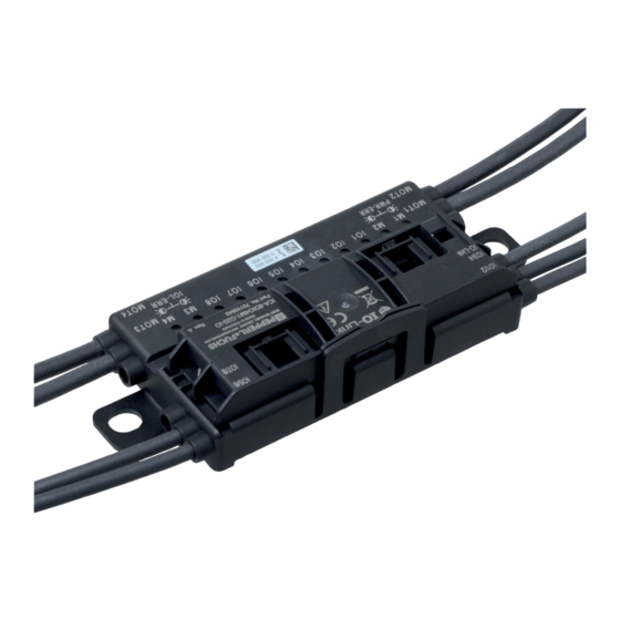
Page 10: Housing
ICA-8DIO4M1-G20-IO Product Description You can download the corresponding manual for each version from our website www.pepperl- fuchs.com. For detailed information on the structure and assignment of the process data image, see chap- ter 4. Housing The housing is made entirely of plastic, except for the hinge pins for the hinge cable guide. - Page 11 ICA-8DIO4M1-G20-IO Product Description LEDs IO1 – IO8 Status Function Input/output not active Yellow lit up Input/output active No communication with IO-Link master All LEDs flashing red State of the input/output Yellow unchanged Red lit up Overload or short circuit of the output or supply...
-
Page 12: Interfaces And Connections
ICA-8DIO4M1-G20-IO Product Description Interfaces and Connections Flat Cable Specification The motor control module is compatible with the AS-Interface standard cable in accordance with IEC 62026-2. The following AS-Interface cable types are available with "UL Recognized" approval: AS-Interface Cable Types with UL Approval... -
Page 13: Io-Link Interface Properties
ICA-8DIO4M1-G20-IO Product Description Plug Assignment Connection For Connector Plug Type/Assignment Input: LF004-GS1-A in accordance with Inputs/outputs IEC/EN 61076-2-104 M8, 4-pin, socket, union nut, A-coded Matching female connector: LM004-Gx1-A or similar 1: V+ sensor supply 2: IO2, IO4, IO6, IO8 3: V- sensor supply... -
Page 14: Installation
Retain the original packaging in case the device must be stored or shipped again at a later date. Should you have any questions, please contact Pepperl+Fuchs. Mounting Mount the device with both brackets (1) on a solid, continuous surface. - Page 15 ICA-8DIO4M1-G20-IO Installation Warning! Damage to contacts Only connect or disconnect the module connections when the module is de–energized. Other- wise, the connections can be damaged. Connecting the Flat Cable on the Narrow Side The profile edge is visible from above.
- Page 16 ICA-8DIO4M1-G20-IO Installation Connecting the Flat Cable on the Wide Side The profile edge is not visible from above. For clarity in the figure below, a dotted line rep- resents where the edge would be. Open the cable guide by pushing the locking bracket (1) slightly to the side.
-
Page 17: Connecting Motors And Sensors
ICA-8DIO4M1-G20-IO Installation Figure 3.4 Flat cable inserted incorrectly (profile edge shown as dotted line) Connecting Motors and Sensors IO-Link, the inputs and outputs, and the motors are connected via standard round plug connec- tors. IO1/2, IO3/4, IO5/6, IO7/8 IO-Link IO1,3,5,7 IO1...8... -
Page 18: Io-Link Process Data
ICA-8DIO4M1-G20-IO IO-Link Process Data IO-Link Process Data Input Process Data Structure The process data input by the motor control module consists of 64 bits (8 byte). The following table provides an overview of the order and structure of the process data. -
Page 19: Output Process Data Structure
ICA-8DIO4M1-G20-IO IO-Link Process Data Name Long Name Data Type Length Offset Value Function/Description CNTREV Counting Direction Boolean 1 bit 0 = inactive Counting direction Change 1 = active changed since the last reset MCRDY Motor Controller Boolean 1 bit 0 = inactive... - Page 20 ICA-8DIO4M1-G20-IO IO-Link Process Data Name Long Name Data Type Length Offset Value Function/Description CNTRRE- Counter Reset Direc- Boolean 1 bit 0 -> 1 = reset Resets the counter direc- tion Change tion change flag. CNTPRE Counter Preset Boolean 1 bit 0 ->...
- Page 21 ICA-8DIO4M1-G20-IO IO-Link Process Data Name Long Name Data Type Length Offset Value Function/Description BRKC Brake Control Boolean 1 bit 0 = inactive Sets the motor brake 1 = active SPDC Speed Control Boolean 1 bit 0 = SPEED1 Sets the speed on motor 4...
-
Page 22: Io-Link Parameters
ICA-8DIO4M1-G20-IO IO-Link Parameters IO-Link Parameters Device-Specific Operating/Configuration Parameters Index/ Off- .sub Parameter ess Data Type Length set Value Range ault Description Motor 1 Control Parameters MCC1 Record (1) 4 byte Operating parameters of the (0x40) Param motor control channel MCC1. - Page 23 ICA-8DIO4M1-G20-IO IO-Link Parameters Index/ Off- .sub Parameter ess Data Type Length set Value Range ault Description Motor 1 Control Configuration MCC1 Con- Record (1) 5 byte Configuration parameters of the (0x48) motor control channel MCC1. Output UInteger 0: digital output...
- Page 24 ICA-8DIO4M1-G20-IO IO-Link Parameters Index/ Off- .sub Parameter ess Data Type Length set Value Range ault Description Motor 4 Control Configuration MCC4 Con- Record (1) 5 byte Configuration parameters of the (0x4B) motor control channel MCC4. Output UInteger 0: digital output...
- Page 25 ICA-8DIO4M1-G20-IO IO-Link Parameters Index/ Off- .sub Parameter ess Data Type Length set Value Range ault Description Runtime UInteger 0: deactivated Motor runtime interval for a main- interval (32) 1 ... 1000000 tenance requirement warning in hours Run cycle UInteger 0: deactivated...
- Page 26 ICA-8DIO4M1-G20-IO IO-Link Parameters Index/ Off- .sub Parameter ess Data Type Length set Value Range ault Description IO Port 3 Configuration IOC3 Con- Record (1) 3 byte Configuration of IO channel 3. (0x5A) I/O mode UInteger 0: digital input I/O mode as digital input or digital 1: digital output output.
-
Page 27: Device Parameters
ICA-8DIO4M1-G20-IO IO-Link Parameters Index/ Off- .sub Parameter ess Data Type Length set Value Range ault Description I/O logic UInteger 0: high active - Logic for the digital input/output. not inverted 1: low active - inverted Input filter UInteger 0: deactivated Filter time for digital input signals. -
Page 28: Standard Configuration Parameters
ICA-8DIO4M1-G20-IO IO-Link Parameters Index/ Off- .sub Parameter ess Data Type Length set Value Range ault Description Encoder UInteger 0 = single-input Configures the connected rotary input mode rotary encoder encoder 1 = dual-input rotary encoder Compensa- UInteger 0: on Activates the speed compensa-... -
Page 29: Specific Device Information
ICA-8DIO4M1-G20-IO IO-Link Parameters Specific Device Information Index/ Off- .sub Parameter ess Data Type Length set Value Range ault Description Unique Character 128 Specific device identification in (0xBF) Product ID byte accordance with DIN SPEC 91406 Table 5.4 Operating Monitor Index/ Off- .sub... -
Page 30: Diagnostics
ICA-8DIO4M1-G20-IO IO-Link Parameters Index/ Off- .sub Parameter ess Data Type Length set Value Range ault Description Motor 4 Operating Monitor MCC4 Record (1) 12 byte Status of motor channel 4 (0xDB) Operating Runtime UInteger 0 ... Runtime since the last mainte-... - Page 31 ICA-8DIO4M1-G20-IO IO-Link Parameters Index/ Off- .sub Parameter ess Data Type Length set Value Range ault Description Operating Integer (8) -40 ... +125 Current internal temperature in Tempera- communication in °C ture - Com- munication Diagnostics of the Motor Maintenance MCC Diag...
- Page 32 ICA-8DIO4M1-G20-IO IO-Link Parameters Index/ Off- .sub Parameter ess Data Type Length set Value Range ault Description M1 - power Boolean 0: inactive Indicates an overload at the out- output over- 1: active put of this motor channel load M2 - fuse...
-
Page 33: Device-Specific Commands
ICA-8DIO4M1-G20-IO IO-Link Parameters Index/ Off- .sub Parameter ess Data Type Length set Value Range ault Description IO7 output Boolean 0: inactive Indicates an overload at the out- overload 1: active put of this IO connection alarm IO8 output Boolean 0: inactive... -
Page 34: Repair And Servicing
ICA-8DIO4M1-G20-IO Repair and Servicing Repair and Servicing The device must not be repaired, changed, or manipulated. In case of failure, always replace the device with an original device. -
Page 35: Appendix
ICA-8DIO4M1-G20-IO Appendix Appendix Event Codes Standard Applications Event Event Instance Type Mode Qualifier Code Description Parameter Error Appear/Disap- 0xF4/0xB 0x6320 Internal parameter set corrupted error pear • Reset device • Replace device Hardware error APP Error Appear/Disap- 0xF4/0xB 0x5010 Hardware error beyond repair pear •... -
Page 36: Error Codes
ICA-8DIO4M1-G20-IO Appendix Error Codes In the case of a fault, the module transmits the following error codes. An error code consists of two bytes. The byte with the higher value, in this case 0x80, represents the IO-Link device as the transmitter. The byte with the lower value represents the actual fault. -
Page 37: Ascii Table
ICA-8DIO4M1-G20-IO Appendix ASCII table ASCII hex ASCII ASCII hex ASCII Space " & < >... - Page 38 Pepperl+Fuchs Quality Download our latest policy here: www.pepperl-fuchs.com/quality www.pepperl-fuchs.com © Pepperl+Fuchs · Subject to modifications Printed in Germany / DOCT-6768...
Need help?
Do you have a question about the ICA-8DIO4M1-G20-IO and is the answer not in the manual?
Questions and answers