
Related Manuals for Grundig GD-RN-CT8832N


Summary of Contents for Grundig GD-RN-CT8832N
- Page 1 User Manual GD-RN-AC2004P GD-RN-AP8632P GD-RN-AC2416N GD-RN-AT8864N GD-RN-AC2416P GD-RN-CT8832N GD-RN-AP8616P GD-RT-AT819128N grundig-security.com...
-
Page 2: Table Of Contents
Content Introduction ......................... 7 Model Overview ......................... 7 Key Features of the NVRs ......................8 Front Panel View ........................12 Remote Control ........................18 USB Mouse ..........................23 OSD Keyboard ........................... 24 Rear Panel View ........................25 Getting Started ........................31 2.1 Recorder Startup .......................... - Page 3 5.8 Configuring Redundant Recording and Capture ................85 5.9 Configuring the HDD Group for Recording and Capture ..............86 5.10 Files Protection ..........................87 5.10.1 Locking the Recording Files ........................87 5.10.2 Setting the HDD Property to Read-only ....................90 Playback ..........................
- Page 4 8.1 Setting a Motion Detection Alarm ....................115 8.2 Setting Sensor Alarms ........................117 8.3 Detecting a Video Loss Alarm ......................119 8.4 Detecting a Video Tampering Alarm....................120 8.5 Handling an Exceptions Alarm ....................... 122 8.6 Setting Alarm Response Actions ....................122 8.7 Triggering or Clearing an Alarm Output Manually ................
- Page 5 11.6 Advanced Search ......................... 148 Network Settings ......................150 12.1 Configuring General Settings ....................... 150 12.2 Configuring Advanced Settings ....................151 12.2.1 Configuring DDNS..........................151 12.2.2 Configuring the NTP Server ......................... 153 12.2.3 Configuring SNMP ..........................154 12.2.4 Configuring More Settings ........................155 12.2.5 Configuring the HTTPS Port .........................
- Page 6 14.5 Configuring the Quota Mode ...................... 179 14.6 Configuring the Disk Clone ......................180 14.7 Checking the HDD Status ......................181 14.8 HDD Detection ..........................182 14.9 Configuring HDD Error Alarms ..................... 184 15. Camera Settings ......................... 185 15.1 Configuring the OSD Settings ...................... 185 15.2 Configuring the Privacy Mask ......................
-
Page 7: Introduction
1. Introduction Thank you for purchasing a Grundig product. Before installing or connecting the product, please read first the following documents which you can find on the CD in the product package: - Legal Disclaimer - Safety Instructions - Installation Manual for the respective product model Further information about the product like Data Sheets, CE Documents, etc. -
Page 8: Key Features Of The Nvrs
Up to 16 SATA hard disks and 1 eSATA disk can be connected for GD-RN-AT819128N, up to 8 SATA hard disks and 1 eSATA disk can be connected for GD-RN-AT8864N and GD-RN-CT8832N, 4 SATA hard disks for GD-RN-AP8616P and GD-RN-AP8632P, 2 SATA hard disks for GD-RN-AC2416N and GD-RN-AC2416P, and 1 SATA hard disk for GD-RN-AC2004P. - Page 9 <Hot-swappable RAID Storage Scheme> which can be enabled and disabled on your demand. 16 arrays can be configured. ‒ GD-RN-AT8864N, GD-RN-CT8832N and GD-RN-AT819128N support the disk clone to the eSATA disk. Recording, Capture and Playback: Note: <Capture> is supported by GD-RN-AP8616P, GD-RN-AP8632P, GD-RN-AT8864N, GD-RN-CT8832N and GD-RN- AT819128N only.
- Page 10 <Manual Capture>, <Continuous Capture> of video images and <Playback> of captured pictures. ‒ Supports enabling <H.264+> to ensure high video quality with a lowered bitrate. Backup: ‒ Export video data by USB, SATA or eSATA device (for GD-RN-AT8864N, GD-RN-CT8832N and GD-RN- AT819128N only). ‒ Export video clips during <Playback>. ‒...
- Page 11 ‒ Two self-adaptive 10M/100M/1000M Network interfaces for GD-RN-AT8864N and GD-RN-CT8832N, and the <Multi-address> and <Network Fault-tolerance> working modes are configurable. ‒ One self-adaptive 10M/100M/1000M Network interface for GD-RN-AC2416N, GD-RN-AC2416P, GD-RN- AP8616P and GD-RN-AP8632P. ‒ One self-adaptive 10M/100M Network> interface for GD-RN-AC2004P.
-
Page 12: Front Panel View
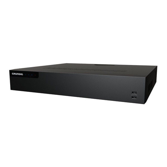
‒ Source code of the application software for demo. ‒ Development support and training for the application system. Front Panel View GD-RN-AT8864N, GD-RN-CT8832N: GD-RN-AT8864N/-CT8832N Panel Description: 12 ENGLISH... - Page 13 Name Function Description ALARM Turns red when a Sensor Alarm is detected. READY Turns blue when the device is functioning properly. Turns blue when device is controlled by an IR Remote. STATUS Turns red when controlled by a keyboard and purple when IR Remote and keyboard is used at the same time.
- Page 14 Name Function Description Enters the <Manual Record> settings menu. Presses this button followed by a numeric button to REC/SHOT call a <PTZ Preset> in <PTZ Control> settings. Turns audio on/off in the <Playback> mode. Enters the <Playback> mode. PLAY/AUTO Automatically scans in the <PTZ Control> menu. Zooms in the PTZ Camera in the <PTZ Control>...
- Page 15 Name Function Description Shows/hides the control interface in the <Playback> mode. Switches between Single-screen and Multi-screen mode. PREV/FOCUS- Adjusts the focus in conjunction with the A/FOCUS+ button in the <PTZ Control> mode. Enters the <PTZ Control> mode. PTZ/IRIS- Adjusts the iris of the PTZ Camera in the <PTZ Control>...
- Page 16 GD-RN-AC2416N, -AC2416P, -AP8616P and -AP8632P: Panel Description: Name Function Description POWER Turns blue when NVR is powered up. Status Blinks red when HDD is reading/writing. Indicators Blinks blue when network connection is functioning Tx/Rx normally. Alarm Turns red when alarm comes up Universal Serial Bus (USB) ports for additional devices USB Interface such as USB mouse.
- Page 17 Panel Description: Name Description Panel lock Locks or unlocks the panel by the key. ● Returns to the previous menu. ● Press it twice quickly to switch the main and auxiliary Exit port. ● In the <Live View> mode, press it to enter the <PTZ Control>...
-
Page 18: Remote Control
Name Description the Left and Right buttons to select the next and previous video files. ● Cycles through channels in the <Live View> mode. ● Controls the movement of the PTZ Camera in the <PTZ Control> mode. Universal Serial Bus (USB) ports for additional devices such USB interfaces as a USB mouse and a USB Hard Disk Drive (HDD). - Page 19 Remote Control Unpairing (Disabling) an IR Remote from an NVR: To unpair an IR Remote from an NVR so that the unit cannot control any NVR functions, proceed as follows: Press the <DEV> key on the IR Remote. Any existing Device ID# will be erased from the unit’s memory and it will no longer function with the NVR.
- Page 20 Name Function Description • To Turn Power On: - If User changed default Device ID# (255): 1. Press the Power On/Off button (1). - If the User has changed the NVR Device ID#: 1. Press the <DEV> button. 2. Press Number buttons enter...
- Page 21 Enable an IR Remote: Press the <DEV> button, enter the NVR <Device ID#> with number keys, press <Enter> to pair the unit with the NVR. Disable an IR Remote: Press the <DEV> button to clear the Device ID#; the unit will no longer be paired with the NVR. Switch to the corresponding channel in the <Live View>...
- Page 22 Advance video a single frame in the Single-frame <Playback> mode. Stop/start the <Auto-switch> in the <Auto-switch> mode Enter the <PTZ Control> mode. Go back to the previous screen. RESERVED Reserved Select all items on a list. Switch between Play and Reverse Play in the <Playback> mode. PTZ Control Adjust the PTZ Camera iris, focus, and zoom.
-
Page 23: Usb Mouse
If the remote control still cannot function properly, please change the remote control and try again or contact the device provider. USB Mouse A regular 3-button (Left/Right/Scroll-wheel) USB mouse can also be used with this NVR. To use a USB mouse: Steps: 1. -
Page 24: Osd Keyboard
OSD Keyboard OSD Keyboard (1) OSD Keyboard (2) Description of the buttons on the OSD Keyboard: Icon Description Icon Description Number English letter … … Lowercase/Uppercase Backspace Switch the keyboard Space Positioning the cursor Exit Symbols Reserved 24 ENGLISH... -
Page 25: Rear Panel View
Rear Panel View GD-RN-AT8864N, GD-RN-CT8832N: GD-RN-AT8864N/-CT8832N Panel Description : Name Description LAN1/LAN2 Interface 2 RJ-45 10/100/1000 Mbps self-adaptive Ethernet interfaces are provided. LINE IN RCA connector for audio input. AUDIO OUT 2 RCA connectors for audio output. HDMI1/HDMI2 HDMI video output connector. - Page 26 GD-RN-AC2416N and GD-RN-AC2416P: GD-RN-AC2416N GD-RN-AC2416P Panel Description: Name Description Audio In RCA connector for audio input. Audio Out RCA connector for audio output. VGA Interface DB9 connector for VGA output. Display local video output and menu. HDMI Interface HDMI video output connector. ALARM IN Connector for <Alarm Input>.
- Page 27 GD-RN-AC2004P: GD-RN-AC2004P Panel Description: Name Description Network Interfaces Network interfaces for the cameras and to provide power with PoE function over Ethernet. Audio In RCA connector for audio input. Audio Out RCA connector for audio output. VGA Interface DB9 connector for VGA output. Display local video output and menu.
- Page 28 GD-RN-AP8616P and GD-RN-AP8632P: GD-RN-AP8616P and GD-RN-AP8632P Panel Description: Name Description LAN Interface 1 network interface. AUDIO OUT RCA connector for audio output. LINE IN RCA connector for audio input. HDMI HDMI video output connector. USB 3.0 interface Universal Serial Bus (USB) ports for additional devices such as a USB mouse and a USB Hard Disk Drive (HDD).
- Page 29 GD-RN-AT819128N GD-RN-AT819128N Panel Description: Name Description HDMI 1/2 HDMI video output connector. Audio in RCA connector for audio input. Audio out RCA connector for audio output. USB 3.0 Universal Serial Bus (USB 3.0) ports for additional devices such as a USB mouse and a USB Hard Disk Drive (HDD). 4 10/100/1000 Mbps self-adaptive Ethernet interfaces.
- Page 30 RS-485 Connector for RS-485 devices. Connector for the keyboard. Ground (needs to be connected when the NVR starts up). Power supply Only one power supply module is provided by default. Two modules power supply modules are optional for redundancy. Decoding board Not Available.
-
Page 31: Getting Started
2. Getting Started 2.1 Recorder Startup Proper startup and shutdown procedures are crucial to expanding the life of the NVR. Before you start: Check that the voltage of the extra power supply is the same as the NVR’s requirement and that the ground connection is working properly. - Page 32 Activating your Recorder: For the first-time access, you need to activate the device by setting an Admin Password. No operation is allowed before activation. You can also activate the device via a Web Browser, Grundig Viewer or the SCMS Client Software.
- Page 33 When the device is activated, the system pops up the message box to remind you to remember the password. Then you can click <Yes> to continue to export the GUID file for the future password resetting. Export GUID File Remind Insert the U-flash disk to your device, and export the GUID file to the U-flash disk in the <Reset Password>...
- Page 34 Set the Unlock Pattern 2. Use the mouse to draw a pattern among the nine dots on the screen. Release the mouse when the pattern is done. Draw the Pattern Note: ‒ Connect at least four dots to draw the pattern. ‒...
- Page 35 Note: If the two patterns are different, you must set the pattern again. Re-set the Pattern Logging in via Unlock Pattern: Note: ‒ Only the Admin User has the permission to unlock the device. ‒ Please configure the pattern first before unlocking. Please refer to Configuring the Unlock Pattern 1.
- Page 36 Note: ‒ If you forgot your pattern, you can select the <Forget My Pattern> or the <Switch User> option to enter the normal <Login> dialog box. ‒ When the pattern you draw is different from the pattern you have configured, you should try again. ‒...
- Page 37 After logging out, the monitor turns to the <Live View> mode and if you want to perform any operations, you need to enter the User Name and the Password again. Steps: Enter the Shutdown menu: Menu > Shutdown Logout Click <Logout>. Note: After you have logged out the system, menu operation on the screen is invalid.
-
Page 38: Using The Wizard For Basic Configuration
After the GUID file is successfully imported, enter the reset password interface to set the new admin password. Refer to Chapter 17.5.3. Click <OK> to set the new password. You can export the new GUID file to the U-flash disk for future password resetting. - Page 39 After the time settings, click the <Next> button which takes you back to the Network Setup Wizard window, as shown in the following Picture. Network Settings Note: Two self-adaptive 10M/100M/1000M network interfaces provided for GD-RN-AT8864N, GD-RN-AP8616P and GD-RN-AP8632P and two working modes are configurable: Multi-address and Network Fault tolerance.
- Page 40 Advanced Network Parameters Click the <Next> button after you configured the network parameters, which takes you to the RAID configuration window. Note: The RAID is supported by GD-RN-AT8864N and GD-RN-AT819128N only. Array Management Click the <Next> button to enter the Array Management window. Click the <Next>...
- Page 41 To initialize the HDD, click the <Init> button. Initialization removes all the data saved in the HDD. 10. Click the <Next> button. You enter the <Adding IP Camera> interface. 11. Click <Search> to search the online IP Camera and the Security status shows whether it is active or inactive.
-
Page 42: Adding And Connecting The Ip Cameras
2.3 Adding and Connecting the IP Cameras 2.3.1 Activating the IP Camera Before adding the camera, make sure the IP camera to be added is in active status. Steps: 1. Select the <Add IP Camera> option from the right-click menu in the <Live View> mode or click Menu>... -
Page 43: Adding The Online Ip Cameras
<Use Admin Password>: when you check the checkbox, the camera (s) will be configured with the same admin password of the operating NVR. Set New Password <Create New Password>: If the admin password is not used, you must create the new password for the camera and confirm it. - Page 44 Quick Adding IP Camera Interface Or you can choose to custom add the IP camera by editing the parameters in the corresponding textfiled and then click the <Add> button to add it. OPTION 2: Steps: Select the <Add IP Camera> option from the right-click menu in the <Live View> mode or click Menu>...
- Page 45 Custom Adding IP Camera Interface You can edit the <IP Address>, <Protocol>, <Management Port>, and other information of the IP camera that is to be added. Note: If the IP camera that is to be added has not been actiavated, you can activate it from the IP camera list on the Camera Management interface.
-
Page 46: Editing The Connected Ip Cameras And Configuring Customized Protocols
Security Level of an IP Camera’s Password Enabling the Password of Visible IP Cameras: For the admin login user account, you can check the checkbox of <Show Password of IP Camera> to enable the showing of the passwords of the successfully added IP cameras in the list. You must enter the admin password to confirm permission. - Page 47 2. Click <OK> to save the settings and exit the Editing interface. To edit advanced parameters: Steps: Drag the horizontal scroll bar to the right side and click the icon. Network Configuration of the Camera You can edit the network information and the <Password> of the camera. Password Configuration of the Camera Click <OK>...
- Page 48 Protocol Management Interface There are 16 customized protocols provided in the system, you can edit the <Protocol Name>; and choose whether to enable the Sub-stream. Choose the protocol type of transmission and choose the transfer protocols. Note: Before customizing the protocol for the network camera, you have to contact the manufacturer of the network camera to consult the URL (uniform resource locator) for getting main stream and sub- stream.
-
Page 49: Editing The Ip Cameras Connected To The Poe Interfaces
Protocol Setting Choose the protocols you just added to validate the connection of the network camera. 2.3.4 Editing the IP Cameras Connected to the PoE Interfaces This chapter is only applicable for the following models: GD-RN-AP8616P, GD-RN-AP8632P, GD-RN-AC2416P and GD-RN-AC2004P. The <PoE>... - Page 50 List of Connected Cameras Note: The cameras connecting to the <PoE> interface cannot be deleted in this menu. Click the button, and select the <Adding Method> in the drop-down list. • <Plug-and-Play>: It means that the camera is connected to the <PoE> interface, so in this case, the parameters of the camera can’t be edited.
-
Page 51: Configuring The Poe Interface
Edit IP Camera Interface – Manual 2.3.5 Configuring the PoE Interface When it requires long-distance <PoE> transmission (100 to 300 m), you can configure the <PoE> channel to the long network cable mode. Steps: 1. Enter the <PoE Configuration> interface. 2. - Page 52 Note: ‒ The <PoE> is enabled with the short network cable mode (<OFF>) by default. ‒ The bandwidth of the IP Camera connected to the <PoE> via a long network cable (100 - 300 meters) cannot exceed 6 MP. ‒ The allowed max.
-
Page 53: Live View
Live View 3.1 Introduction of Live View <Live View> shows you the video image received from each camera in real time. The NVR automatically enters the <Live View> mode when it is powered on. It is also at the very top of the menu hierarchy, thus pressing the <ESC>... - Page 54 • <Playback>: Playback the recorded videos for the current day. • <Aux Monitor>: the NVR checks the connection of the output interfaces to define the main and auxiliary output interfaces. The priority level for the main and aux output is HDMI1/VGA1> HDMI2/VGA2 (for GD-RN-AT8864N) and HDMI>...
- Page 55 Functions Front Panel Operation Show single screen Press the corresponding Alphanumeric button. E.g. Press 2 to display only the screen for channel 2. Show multi-screen Press the PREV/FOCUS- button. Manually switch Next screen: <Right>/<Down> direction button. screens Previous screen: <Left/Up> direction button. Auto-switch Press the <Enter>...
- Page 56 Name Description Common Menu Quick access to the sub-menus which you frequently visit. Menu Enter the <Main> menu of the system by right clicking the mouse. Switch to the single full screen by choosing a channel number from Single Screen the dropdown list.
- Page 57 Using an Auxiliary Monitor: Certain features of the <Live View> are also available while in an Aux monitor. These features include: <Single Screen>: Switch to a full screen display of the selected camera. Camera can be selected from a dropdown list.
- Page 58 <3D Positioning> (for GD-RN-AP8616P, GD-RN-AP8632P and GD-RN-AT8864N) is for zooming in to/out of the specific area of a live image. Use the left key of mouse to click on the desired position in the video image and drag a rectangle area in the lower right direction, the camera will move the position to the center and enable the rectangle area to zoom in.
- Page 59 Move the mouse onto this icon to show the <Real-time Stream Information> including the <Frame Rate>, the <Bitrate>, the <Resolution> and the <Stream Type>. Information Fisheye Expansion View: Some NVR recorders ( GD-RN-AP8616P, GD-RN-AP8632P and GD-RN-AT8864N) support the <Fisheye Expansion> for a connected <Fisheye Camera> in the <Live View> or in the <Playback> mode. Click on the icon to enter the <Fisheye Expansion>...
-
Page 60: Adjusting The Live View Settings
The settings available in this menu include: <Video Output Interface>: Designates the output to configure the settings. <VGA/HDMI1 and <VGA2/HDMI2> are provided for GD-RN-AT8864N and GD-RN-CT8832N HDMI 1, HDMI 2, and VGA outputs are provided for GD-RN-AT819128N (HDMI 2 video output at up to 4K resolution). - Page 61 Live View- Camera Order Select a <View> mode in , including 1/4/6/8/16/25/32/36/64-window division modes which are supported depending on different models. Select the small window and double-click on the channel number to display the channel on the window. You can click to start the <Live View>...
-
Page 62: Channel-Zero Encoding
3.4 Channel-zero Encoding Sometimes you need to get a remote view of many channels in real time from a web browser or a SCMS (Client Management System) software. In order to decrease the bandwidth requirement without affecting the image quality, channel-zero encoding is supported as an option for you. Steps: 1. -
Page 63: Ptz Controls
4. PTZ Controls 4.1 Configuring PTZ Settings Follow the procedure to set the parameters for <PTZ>. The configuring of the <PTZ> parameters should be done before you control the PTZ Camera. Steps: 1. Enter the <PTZ Settings> interface: Menu >Camera> PTZ PTZ Settings 2. -
Page 64: Setting Ptz Presets, Patrols & Patterns
5. Click the <Apply> button to save the settings. 4.2 Setting PTZ Presets, Patrols & Patterns Before you start: Please make sure that the <Presets>, <Patrols> and <Patterns> should be supported by <PTZ> protocols. Customizing Presets: Follow the steps to set the <Preset> location which you want the PTZ Camera to point to when an event takes place. - Page 65 Click the <PTZ Parameters> button to show the general settings of the <PTZ Control>. PTZ Panel - General Click to enter the <Preset No.> in the corresponding text field. Clic k the <Call Preset> button to call it. Customizing Patrols: <Patrols>...
- Page 66 Key point Configuration Configure <Key Point> parameters such as the <Key Point No.>, the <Duration> of stay for one key point and the <Speed> of the <Patrol>. The <Key Point> is corresponding to the <Preset>. The <Key Point No.> determines the order at which the <PTZ> will follow while cycling through the <Patrol>. The <Duration>...
- Page 67 Patterns can be set by recording the movement of the <PTZ>. You can call the pattern to make the <PTZ> movement according to the predefined path. Steps: 1. Enter the <PTZ Control> interface: Menu > Camera > PTZ PTZ Settings Choose the <Pattern Number>...
- Page 68 PTZ Panel - General Click the <Call Pattern> button to call it. Click the <Stop Pattern> button to stop calling it. Customizing Linear Scan Limit: The Linear Scan can be enabled to trigger the scan in the horizantal direction in the predefined range. Note: This function is supported by some models.
- Page 69 Notes: Before operating this function, make sure the connected camera supports the linear scan and is in private protocol. Follow the procedure to call the linear scan in the predefined scan range. Steps: 1. Click the button <PTZ> in the lower-right corner of the <PTZ Settings> interface; Or you can instead press the <PTZ>...
-
Page 70: Ptz Control Panel
PTZ Panel - One-touch There are 3 one-touch <Park Types> selectable; click the corresponding button to activate the park action. <Park (Quick)>: The dome starts to patrol from the predefined <Preset 1> to <Preset 32> in following order after the <Park Time>. The <Undefined Preset> will be skipped. <Park (Patrol 1)>: The dome starts move according to the predefined <Patrol 1 Path>... - Page 71 PTZ Panel Description of the <PTZ> panel icons: Icon Description Icon Description Icon Description Direction button Zoom+, Focus+, Zoom-, Focus-, and the auto- Iris+ Iris- cycle button The speed of the <PTZ> Light on/off Wiper on/off movement Image 3D-Zoom Menu Centralization Switch to the Switch to the...
-
Page 72: Recording And Capture Settings
5. Recording and Capture Settings 5.1 Configuring Parameters By configuring the parameters you can define the parameters which affect the image quality, such as the <Transmission Stream Type>, the <Resolution> and so on. Before you start: Steps: 1) Make sure that the HDD has already been installed. If not, please install a HDD and initialize it. (Menu>HDD>General) HDD- General 2) Check the storage mode of the HDD... - Page 73 Recording Parameters Parameters Setting for Recording 1) Select the <Record> tab to configure the parameters. You can configure the <Stream Type>, the <Resolution> and other parameters on your demand. <Video Encode>: select the video encoding to <H.265> or <H.264>. <Enable H.264+ Mode>: check the checkbox to enable. Once enabled, the <Max. Bitrate Mode, Max. Bitrate(Kbps)>...
- Page 74 <Pre-record>: The time you set to record before the scheduled time or event. For example, when an alarm triggers the recording at 10:00, and if you set the pre-record time as 5 seconds, the camera records at 9:59:55. <Post-record>: The time you set to record after the event or the scheduled time. For example, when an alarm-triggered recording ends at 11:00, and if you set the <Post-record>...
-
Page 75: Configuring Recording And Capture Schedule
Parameters Settings for Capture Select the <Capture> tab. Capture Parameters Configure the parameters. Click <Apply> to save the settings. Note: The interval is the time period between two capturing actions. You can configure all of the parameters on this menu on your demand. 5.2 Configuring Recording and Capture Schedule Set the <Record Schedule>... - Page 76 Record Schedule Different recording types are marked in different color icons. <Continuous>: This is a scheduled recording. <Event>: This is a Recording triggered by all Event-triggered Alarms. <Motion>: This is a Recording triggered by <Motion Detection>. <Alarm>: This is a Recording triggered by an alarm. <M/A>: This is a Recording triggered by either <Motion Detection>...
- Page 77 Recording Schedule Interface You can click the button to set the accurate time of the schedule. 2. To schedule an <All-day> recording, check the checkbox after the <All Day> item. Edit Schedule 3. To arrange another schedule, set the <Start/End time> for each period. Note: Up to 8 periods can be configured for each day.
- Page 78 Copy Schedule to Other Days 5. Click <OK> to save the setting and to go back to the upper level menu. 6. Click <Apply> in the <Record Schedule> interface to save the settings. Draw the schedule: I. Click on the color icons, you can choose the schedule type as <Continuous> or <Event>. Draw the Schedule II.
-
Page 79: Configuring Motion Detection Recording And Capture
5.3 Configuring Motion Detection Recording and Capture Follow the steps to set the <Motion Detection> parameters. In the <Live View> mode, once a <Motion Detection> event takes place, the NVR can analyze it and do many actions to handle it. Enabling the <Motion Detection>... -
Page 80: Configuring Alarm-Triggered Recording And Capture
7) Click <OK> to go back to the upper level menu. 8) Exit the <Motion Detection> menu. Edit the <Motion Detection Record Schedule>. For the detailed information of schedule configuration, see the Chapter about 5.2 Configuring Recording and Capture Schedule. 5.4 Configuring Alarm-Triggered Recording and Capture Follow the procedure to configure alarm-triggered recording or capture. - Page 81 Alarm Settings 5) Choose the <Alarm-triggered Recording Channel>. 6) Check the checkbox to select the channel. 7) Click <Apply> to save the settings. 8) Click <OK> to go back to the upper level menu. Repeat the above steps to configure other <Alarm Input> parameters. If the settings can also be applied to other <Alarm Inputs>, click <Copy>...
-
Page 82: Configuring Vca Event Recording
5.5 Configuring VCA Event Recording The <Event-triggered Recording> can be configured through the menu. Then events include the <Motion Detection>, <Alarm> and <VCA> events (<Face Detection>/<Face Capture>, <Line Crossing Detection>, <Intrusion Detection>, <Region Entrance Detection>, <Region Exiting Detection>, <Loitering Detection>, <People Gathering Detection>, <Fast Moving Detection>, <Parking Detection>, <Unattended Baggage Detection>, <Object Removal Detection>, <Audio Loss Exception Detection>, <Sudden Change of Sound Intensity Detection>... -
Page 83: Manual Recording And Continuous Capture
Note: The <PTZ Linking> function is only available for the <VCA Settings> of <IP Cameras>. 6. Enter the <Record Schedule Settings> interface (Menu > Record > Schedule > Record Schedule) and then set <VCA> as the <Record Type>. For details, see step 2 in Chapter 5.2 Configuring Recording and Capture Schedule. -
Page 84: Configuring Holiday Recording And Capture
Continuous Capture 2) Click the <Status> button before the camera number to change from 3) Disable <Continuous Capture>. 4) Click the <Status> button to change from Note: The Green icon means that the channel is configured for the capture schedule. After rebooting, all the continuous capture will be canceled. -
Page 85: Configuring Redundant Recording And Capture
Edit Holiday Settings 2) Check the checkbox after <Enable Holiday>. 3) Select the <Mode> from the dropdown list. 4) There are three different modes for the date format to configure a holiday schedule. 5) Set the <Start Date> and the <End Date>. 6) Click <Apply>... -
Page 86: Configuring The Hdd Group For Recording And Capture
Enter the <Record Settings> interface: Menu> Record> Parameters Select the <Record> tab. Click <More Settings> to enter the following interface. Record Parameters 3) Select the <Camera> you want to configure in the drop-down list. 4) Check the checkbox of <Redundant Record/Capture>. 5) Click <OK>... -
Page 87: Files Protection
4. Click to enter the <Edit> interface. 5. Configuring an <HDD Group>. 1) Choose a group number for the <HDD Group>. 2) Click <Apply> and then in the pop-up message box, click <Yes> to save your settings. 3) Click <OK> to go back to the upper level menu. 4) Repeat the above steps to configure more <HDD Groups>. - Page 88 Normal/Smart Playback During <Playback>, click the button to lock the current recording file. Note: In the <Multi-channel Playback> mode, clicking the button will lock all the record files related to the <Playback> channels. You can click the button to pop up the <File Management> interface. Click the <Locked File> tab to check and export the locked files.
- Page 89 Export Select the channels you want to search by checking the checkbox Configure the <Record Type>, <File Type> and <Start/End Time>. Click <Search> to show the results. Export- Search Result Protect the record files. Find the record files you want to protect and then click to change it to indicating that the file is locked.
-
Page 90: Setting The Hdd Property To Read-Only
5.10.2 Setting the HDD Property to Read-only Steps: 1. Enter the <HDD Settings> interface: Menu> HDD HDD General 2. Click to edit the HDD you want to protect. Note: To edit the <HDD Property>, you need to set the storage mode of the HDD to <Group>. See Chapter 14.4 Group Managing a HDD 3. -
Page 91: Playback
6. Playback Playing Back Record Files 6.1.1 Instant Playback Play back the recorded video files of a specific channel in the <Live View> mode. <Channel Switch> is supported. Instant <Playback> by channel Steps: 1. Choose a channel in the <Live View> mode and click in the <Quick Setting Toolbar>. - Page 92 Playback by Time: Play back video files recorded in specified time duration. Multi-channel simultaneous <Playback> and channel switch are supported. Steps: 1. Enter the <Playback> interface: Menu>Playback 2. Select <Normal/Smart> in the drop-down list on the top-left side. 3. Select the <Stream> to <Main Stream> or <Sub-stream>. (GD-RN-AP8616P, GD-RN-AP8632P, GD- RN-AT8864N and GD-RN-AT819128N) 4.
- Page 93 Playback interface Toolbar of Playback You can click the channel(s) to execute <Simultaneous Playback> of multiple channels. 93 ENGLISH...
- Page 94 Note: ‒ For the <Progress Bar>: use the mouse to click on any point of the progress bar or drag the progress. The numbers indicate the <Start/End Time> of the recorded video files. ‒ Playback the bar to locate specific frames. Detailed Explanation of Playback Toolbar: Item Button...
-
Page 95: Playing Back By Smart Search
Item Button Operation Button Operation models) Enable/Disable POS information overlay (Supported by GD-RN- AP8616P, GD-RN-AP8632P, GD-RN-AT8864N only) Note: The <Fisheye Expansion View> feature is not supported by GD-RN-AT819128N. Please refer to Chapter 3.2.5 Fisheye Expansion for the description and operation of the <Fisheye Expansion>. Note: The <Playing Speed>... - Page 96 Playback by Smart Search 5. Click the radio button to switch to the <Playback by Smart Search>. 6. Set the rules and areas for <Smart Search> of <Line Crossing Detection>, <Intrusion Detection> or <Motion Detection> Event triggered recording. <Line Crossing Detection> ...
-
Page 97: Playing Back By Event Search
6.1.4 Playing Back by Event Search Play back record files on one or several channels searched by <Event Type> (e.g., <Alarm Input>, <Motion Detection> and <VCA>). Steps: 1. Enter the <Playback> interface: Menu>Playback 2. Select the <Event> in the drop-down list on the top-left side. 3. -
Page 98: Playing Back By Tag
Select a result item and click to play back the file. Note: Pre-play and post-play can be configured. Enter the <Playback> interface. The toolbar in the bottom part of the <Playback> interface can be used to control the playing process. Interface of Playback by Event You can click to select the previous or the next event. - Page 99 Interface of Playback by Time Click to add a <Default Tag>. Click to add a <Customized Tag> and an <Input Tag Name>. Note: Max. 64 tags can be added to a single video file. Tag management. Click to enter the <File Management> interface and click <Tag> to manage the tags. You can check, edit, and delete tag(s).
-
Page 100: Playing Back By Sub-Periods
2. Select the <Stream> to <Main Stream> or <Sub-stream>. Choose <Channels>, edit the <Start Time> and the <End Time> and then click <Search> to enter the <Search Result> interface. Note: You can enter a <Keyword> in the textbox to search the tag on your command. Click to play back the selected tag file. -
Page 101: Playing Back By System Logs
6.1.7 Playing Back by System Logs Play back record file(s) associated with channels after searching system logs. Steps: 1. Enter the <Log Information> interface. 2. Menu> Maintenance> Log Information 3. Click the <Log Search> tab to enter the <Playback by System Logs>. 4. -
Page 102: Playing Back External File
The toolbar in the bottom part of the <Playback> interface can be used to control the playing process. Interface of Playback by Log 6.1.8 Playing Back External File Perform the following steps to look up and play back files in the external devices.] Steps: 1. -
Page 103: Auxiliary Functions Of Playback
Result of Picture Playback The toolbar in the bottom part of the <Playback> interface can be used to control the playing process. Picture Playback Toolbar Detailed Explanation of Picture-playback Toolbar: Button Function Button Function Button Function Button Function Previous Play reverse Play Next picture picture... -
Page 104: Thumbnails View
Click this button to set the speed to <Single Frame>. One click on this button , one click on the <Playback Screen> or <Enter> button on the front panel represents <Playback> or <Reverse Playback> of one frame. 6.2.2 Thumbnails View With the thumbnails view on the <Playback>... -
Page 105: File Management
1. Click on the <Playback Control Bar> to enter the <Digital Zoom> interface. 2. You can zoom in the image to different proportions (1 to16X) by moving the sliding bar from . You can also scroll the mouse wheel to control the zoom in/out. Draw Area for Digital Zoom Right-click the image to exit the <Digital Zoom>... -
Page 106: Backup
7. Backup 7.1 Backing up Record Files 7.1.1 Quick Export Export record files to backup device(s) quickly. Steps: 1. Enter the <Video Export> interface: Menu> Export> Normal Choose the channel(s) you want to back up and click the <Quick Export> button. Note: The time duration of record files on a specified channel cannot exceed one day. - Page 107 Quick Export using USB1-1 Stay in the <Export> interface until all record files are exported. Export Finished Check the backup result. Choose the record file in the <Export> interface and click to check it. Note: The Player <player.exe> will be exported automatically during record file export. Checkup of Quick Export Result Using USB1-1 107 ENGLISH...
-
Page 108: Backing Up By Normal Video/Picture Search
7.1.2 Backing up by Normal Video/Picture Search The record files can be backed up to various devices, such as USB devices (USB flash drives, USB HDDs and USB writers), SATA writers and e-SATA HDDs. Note: The <eSATA HDD> is supported by GD-RN-AT8864N and GD-RN-AT819128N only. Backup using USB flash drives and USB HDDs: Steps: 1. - Page 109 Result of Normal Video Search for Backup Export the video files or picture files. Click the <Export All> button to export all of the files. Or you can select recording files you want to back up and click the <Export> button to enter the <Export>...
-
Page 110: Backing Up By Event Search
Stay in the <Export> interface until all record files are exported with a pop-up message box saying “Export finished”. Export Finished Note: The backup of video files using a USB writer or a SATA writer has the same operating instructions. Please refer to steps described above. -
Page 111: Backing Up Video Clips Or Captured Playback Pictures
5. The matched video files are displayed in <Chart> or <List> display mode. Select video files from the <Chart> or <List> interface to export. Result of Event Search 6. Export the video files. Please refer to step 5 of Chapter 7.1.2 Backing up by Normal Video Search for details. -
Page 112: Managing Backup Devices
4. Export the video clips or captured pictures in <Playback>. Please refer to step 5 of Chapter 7.1.2 Backing up by Normal Video Search for details. 7.2 Managing Backup Devices Management of USB flash drives, USB HDDs and eSATA HDDs. Steps: 1. -
Page 113: Hot Spare Device Backup
7.3 Hot Spare Device Backup The device can form an <N+1 Hot Spare> system. The system consists of several working devices and a <Hot Spare>device; when the working device fails, the <Hot Spare>device switches into operation, thus increasing the reliability of the system. Note: Please contact the dealer for details of models which support the <Hot Spare>... -
Page 114: Managing The Hot Spare System
7.3.3 Managing the Hot Spare System Steps: 1. Enter the <Hot Spare Settings> interface of the <Hot Spare>device: Menu > Configuration > Hot Spare The connected working device is displayed on the device list. 2. Check the checkbox to select the working device from the device list, and Click the <Add> button to link the working device to the <Hot Spare>device. -
Page 115: Alarm Settings
8. Alarm Settings 8.1 Setting a Motion Detection Alarm Steps: 1. Enter the <Motion Detection> interface of the <Camera Management> and choose a camera you want to set up for <Motion Detection>: Menu> Camera> Motion Motion Detection Setup Interface 2. Set up the <Detection Area> and the <Sensitivity>. Check <Enable Motion Detection>, use the mouse to draw detection area(s) and drag the <Sensitivity>... - Page 116 Set Trigger Camera of Motion Detection Set up the <Arming Schedule> of the channel. 1) Select the <Arming Schedule> tab to set the <Arming Schedule> of <Handling Actions> for the <Motion Detection>. 2) Choose one day of a week and up to eight time periods can be set within each day. 3) Click <Apply>...
-
Page 117: Setting Sensor Alarms
8.2 Setting Sensor Alarms Set the <Handling Action> of an <External Sensor Alarm>. Steps: 1. Enter <Alarm Settings> of the <System Configuration> and select an <Alarm Input>: Menu> Configuration> Alarm Select the <Alarm Input> tab to enter the <Alarm Input Settings> interface. Alarm Status Interface of System Configuration Set up the <Handling Action>... - Page 118 4. Select the <Trigger Channel> tab and select one or more channels which will start to <Record>/<Capture> or become <Full-screen Monitoring> when an <External Alarm> is coming in, and click <Apply> to save the settings. 5. Select the <Arming Schedule> tab to set the <Arming Schedule> of <Handling Actions>. Set Arming Schedule of Alarm Input Choose one day of a week (a maximum of eight time periods can be set within each day) and click <Apply>...
-
Page 119: Detecting A Video Loss Alarm
If you want to set a <Handling Action> of another <Alarm Input>, repeat the above steps. Or you can click the <Copy> button on the <Alarm Input Setup> interface and check the checkbox of <Alarm Inputs> to copy the settings to them. Copy Settings of Alarm Input 8.3 Detecting a Video Loss Alarm Detect video loss of a channel and take alarm response action(s). -
Page 120: Detecting A Video Tampering Alarm
3. Check the checkbox of <Enable Video Loss Alarm>, and click to set up a <Handling Action> for <Video Loss>. 4. Set up the <Arming Schedule> of the <Handling Actions>. 1) Select the <Arming Schedule> tab to set the channel’s <Arming Schedule>. 2) Choose one day of a week and up to eight time periods can be set within each day. - Page 121 Video Tampering Setting Interface 2. Set the <Video Tampering Handling Action> of the channel. 1) Check the checkbox of <Enable Video Tampering Detection>. 2) Drag the <Sensitivity> bar to set a proper sensitivity level. Use the mouse to draw an area you want to detect <Video Tampering>.
-
Page 122: Handling An Exceptions Alarm
4. Select the <Linkage Action> tab to set up <Alarm Response Actions> for the <Video Tampering Alarm> (please refer to Chapter 8.6 Setting Alarm Response Actions). 5. Click the <OK> button to complete the <Video Tampering Settings> of the channel. 8.5 Handling an Exceptions Alarm Exception settings refer to the <Handling Action>... - Page 123 Event Hint Settings Interface: Click to set the Type of Event to be displayed on the image. Event Hint Settings Interface Click the <OK> button to finish the settings. <Full Screen Monitoring>: When an <Alarm> is triggered, the local monitor (VGA, HDMI or BNC monitor) displays in full screen the video image from the alarming channel configured for <Full Screen Monitoring>.
- Page 124 Note: The <Alarm> signal will be transmitted automatically in the <Detection> mode when a remote <Alarm Host> is configured. Please refer to Chapter 11.2.6 Configuring More Settings for details of <Alarm Host> configuration. <Email Linkage>: Send an email with <Alarm> information to a user or users when an <Alarm> is detected. Please refer to Chapter 11.2.8 Configuring Email for details of <Email>...
-
Page 125: Triggering Or Clearing An Alarm Output Manually
Set Arming Schedule of Alarm Output 4. Repeat the above steps to set up an <Arming Schedule> of other days of a week. You can also use the <Copy> button to copy an <Arming Schedule> to other days. 5. Click the <OK> button to complete the <Video Tampering Settings> of the <Alarm Output No.> 6. - Page 126 Clear or Trigger Alarm Output Manually 126 ENGLISH...
-
Page 127: Pos Configuration
9. POS Configuration Note: The <POS> feature is only supported by the NVR models GD-RN-AP8616P, GD-RN-AP8632P and GD-RN- AT8864N. 9.1 Configuring the POS Settings Steps: 1. Enter the <POS Settings> interface. Menu > Configuration > POS> POS Settings 2. Select the <POS> from the drop-down list. Note: The amount of <POS>... - Page 128 Universal Protocol Settings <EPSON > The fixed <Start Line Tag> and <End Line Tag> are used for <EPSON> protocol. <AVE> The fixed <Start Line Tag> and <End Line Tag> are used for <AVE> protocol. And the <Serial Port> and the <Virtual Serial Port>...
- Page 129 2) Set the <Allowed Remote IP Address> of the device sending the <POS Message>. TCP Connection Settings <UDP Connection> 3) When using a <UDP Connection>, the port must be set from <1> to <65535> and the port for each <POS> machine must be unique. 4) Set the <Allowed Remote IP Address>...
- Page 130 RS-232 Settings Multicast Connection When connecting the NVR and the <POS> machine via <Multicast> protocol, set the <Multicast Address> and <Port>. Multicast Settings Sniff Connection Connect the NVR and the <POS> machine via <Sniff>. Configure the <Source Address> and the <Destination Address>...
-
Page 131: Configuring The Overlay Channel
6) Select the font color for the characters. Overlay Character Settings Note: You can adjust the size and the position of the textbox on the preview screen of the <POS Settings> interface by dragging the frame. Click <Apply> to activate the settings. (Optional) You can click the <Copy>... -
Page 132: Configuring The Pos Privacy Information Filtering
Overlay Channel Settings You can also click to overlay all <POS> items to the first 8 channels in order. And is used to clear all <POS Overlay Settings>. Click the <Apply> button to save the settings. 9.3 Configuring the POS Privacy Information Filtering You can set the <POS Privacy Information>... -
Page 133: Configuring The Pos Alarm
9.4 Configuring the POS Alarm Set the <POS Alarm> parameters to trigger certain channels to start recording or trigger <Full Screen Monitoring>, <Audio Warning>, <Notify the Surveillance Center>, <Send Email> and so on. Steps: 1. Enter the <POS Settings> interface: Menu > Configuration > POS> POS Settings Follow the steps in Chapter 9.1-9.2 to configure the <POS Settings>... - Page 134 Click the <OK> button to complete the <POS Settings> of the channel. Select the <PTZ Linking> tab and set the <PTZ Linkage> of the <POS Alarm>. Set <PTZ Linking> parameters and click the <OK> button to complete the settings of the <Alarm Input>.
-
Page 135: Vca Alarm
10. VCA Alarm The NVR supports the <VCA Detection Alarm> (<Face Detection>, <Vehicle Detection>, <Line Crossing Detection> and <Intrusion Detection>, <Region Entrance Detection>, <Region Exiting Detection>, <Unattended Baggage Detection>, <Object Removal Detection>, <Audio Loss Exception Detection>, <Sudden Change of Sound Intensity Detection>, and <Defocus Detection>) sent by IP Camera. The <VCA Detection>... -
Page 136: Vehicle Detection
Click the <Rule Settings> button to set the <Face Detection> rules. You can click-and-drag the slider to set the detection <Sensitivity>. <Sensitivity>: Range [1-5]. The higher the value is, the more easily the face can be detected. Click <Apply> to activate the settings. 10.2 Vehicle Detection This function is not available in all models. -
Page 137: Line Crossing Detection
Click <Save> to save the settings. Note: Please refer to the User Manual of the Network Camera for detailed instructions for the <Vehicle Detection>. 10.3 Line Crossing Detection This function can be used for detecting people, vehicles and objects who cross a set virtual line. The <Line Crossing Direction>... -
Page 138: Intrusion Detection
Set Line Crossing Detection Rules 8. Click and set two points in the preview window to draw a virtual line. You can use this icon to clear the existing virtual line and to re-draw it. Note: Up to 4 rules can be configured. Draw Line for Line Crossing Detection Click <Apply>... - Page 139 2. Select the camera to configure the <VCA>. You can click the checkbox of <Save VCA Picture> to save the captured pictures of <VCA Detection>. 3. Select the <VCA Detection> type to <Intrusion Detection>. 4. Check the <Enable> checkbox to enable this function. 5.
-
Page 140: Region Entrance Detection
Note: Up to 4 rules can be configured. Draw Area for Intrusion Detection Click <Apply> to save the settings. 10.5 Region Entrance Detection This function is not available in all models. The <Region Entrance Detection> function detects people, vehicles or other objects which enter a pre- defined virtual region from the outside place and certain actions can be taken when the alarm is triggered. -
Page 141: Region Exiting Detection
You can use this icon to clear the existing virtual line and to re-draw it. Note: Up to 4 rules can be configured. 8. Click <Apply> to save the settings. 10.6 Region Exiting Detection The <Region Exiting Detection> function detects people, vehicles or other objects which exit from a pre- defined virtual region and certain actions can be taken when the alarm is triggered. -
Page 142: Audio Exception Detection
Note: Please refer to the Chapter 9.4 Intrusion Detection for operating steps to configure the <Object Removal Detection>. The <Threshold> [5s-20s] in the <Rule Settings> defines the time for which objects are removed from the region. If you set the value as <10>, then he <Alarm> is triggered after the object disappears from the region for 10 seconds. -
Page 143: Sudden Scene Change Detection
<Sensitivity>: Range [1-100], the smaller the value is, the more severe the change should be to trigger the detection. <Sound Intensity Threshold>: Range [1-100], it can filter the sound in the environment, the louder the environment sound, the higher the value should be. You can adjust it according to the real environment. -
Page 144: Loitering Detection
3. Select the <VCA Detection> type to <PIR Alarm>. 4. Click to configure the <Trigger Channel>, the <Arming Schedule> and the <Linkage Actions> for the <PIR Alarm>. 5. Click the <Rule Settings> button to set the rules. Please refer to Chapter 9.2 Face Detection for instructions. -
Page 145: Parking Detection
Detection>. ‒ The <Sensitivity> in the <Rule Settings> defines the moving speed of the object which can trigger the <Alarm>. The higher the value is, the more easily a moving object can trigger the alarm. ‒ Up to 4 rules can be configured. 10.16 Parking Detection Note: This function is only available for the NVR model GD-RN-AT819128N. -
Page 146: Vca Search
11. VCA Search With the configured <VCA Detection>, the NVR supports the <VCA Search> for the <Behavior Analysis>, <Face Capture>, <People Counting> and <Heat Map> results. 11.1 Face Search This function is not available in all models. When there are detected face pictures captured and saved on an HDD, then you can enter the <Face Search>... -
Page 147: Plate Search
2. Select the camera(s) for the <Behavior Search>. 3. Specify the <Start Time> and the <End Time> for searching the matched pictures. 4. Select the <VCA Detection Type> from the dropdown list including the <Line Crossing Detection>, <Intrusion Detection>, <Unattended Baggage Detection>, <Object Removal Detection>, <Region Entrance Detection>, <Region Exiting Detection>, <Parking Detection>, <Loitering Detection>, <People Gathering Detection>... -
Page 148: Heat Map
Steps: 1. Enter the <Counting> interface: Menu> VCA Search> Counting 2. Select the <Camera> for the people counting. 3. Select the <Report Type> to <Daily Report>, <Weekly Report>, <Monthly Report> or <Annual Report>. 4. Set the statistics time. 5. Click the <Counting> button to start people counting statistics. 6. - Page 149 (Configuration> Advanced Configuration> Smart Event). Please refer to the user manual of the Thermal Network Camera for details. Steps: 1. Enter the <Advanced Search> interface: Menu > VCA Search > Advanced Search 2. Select the <Camera(s)> for the <Advanced Search>. 3.
-
Page 150: Network Settings
12. Network Settings 12.1 Configuring General Settings <Network Settings> must be properly configured before you operate the NVR over a network. Steps: 1. Enter the <Network Settings> interface: Menu >Configuration>Network 2. Select the <General> tab. Network Settings Interface 3. In the <General Settings> interface, you can configure the following settings: <Working Mode>, <NIC Type>, <... -
Page 151: Configuring Advanced Settings
Note: Two self-adaptive <10M/100M/1000M Network> interfaces for GD-RN-AT8864N and GD-CI-CT8832N and the <Multi-address> and <Network Fault Tolerance> working modes are configurable. One self-adaptive <10M/100M/1000M Network> interface for GD-RN-AC2416N, GD-RN-AC2416P, GD- RN-AP8632P and GD-RN-AP8616P. One self-adaptive <10M/100M Network> interface for GD-RN-AC2004P. Four self-adaptive <... - Page 152 IPServer Settings Interface <DynDNS>: Enter the <Server Address> for <DynDNS> (i.e. members.dyndns.org). In the <Device Domain Name> text field, enter the domain obtained from the <DynDNS> website. Enter the <User Name> and <Password> registered in the <DynDNS> website. DynDNS Settings Interface <PeanutHull>: Enter the <User Name>...
-
Page 153: Configuring The Ntp Server
NO-IP Settings Interface Click to register an account if you do not have one and use the account to log 12.2.2 Configuring the NTP Server A <Network Time Protocol (NTP) Server> can be configured on your NVR to ensure the accuracy of the system date/time. -
Page 154: Configuring Snmp
3. Check the <Enable NTP> checkbox to enable this feature. 4. Configure the following <NTP Settings>: <Interval>: Time interval between the two synchronizing actions with the <NTP Server>. The unit is one minute. <NTP Server>: <IP Address> of the <NTP Server>. <NTP Port>: <Port>... -
Page 155: Configuring More Settings
6. Click the <Apply> button to save and exit the interface. Note: Before setting the <SNMP>, please download the <SNMP> software and manage to receive the device information via the <SNMP Port>. By setting the <Trap Address>, the NVR is allowed to send the <Alarm Event>... -
Page 156: Configuring The Https Port
Configure More Settings Click the <Apply> button to save and exit the interface. 12.2.5 Configuring the HTTPS Port <HTTPS> provides authentication of the web site and associated web server that one is communicating with, which protects against Man-in-the-middle attacks. Perform the following steps to set the <Port Number>... - Page 157 HTTPS Settings OPTION 1: Create the <Self-signed Certificate> 1) Click the <Create> button to create the following dialog box. Create Self-signed Certificate 2) Enter the <Country>, <Host Name>/<IP>, <Validity> and other information. 3) Click <OK> to save the settings. OPTION 2: Create the authorized certificate 1) Click the <Create>...
-
Page 158: Configuring Email
3) After receiving the signed valid <Certificate>, import the <Certificate> to the device. 6. There will be the certificate information after you successfully create and install the certificate. Installed Certificate Property 7. Check the checkbox to enable the <HTTPS> function. 8. - Page 159 Network Settings Interface 3. Click <Apply> to save the settings. 4. Select the <Email> tab to enter the <Email Settings> interface. Email Settings Interface 5. Configure the following <Email Settings>: <Enable Server Authentication> (optional): Check the checkbox to enable the <Server Authentication Feature>.
-
Page 160: Configuring The Nat
<Select Receivers>: Select the receiver. Up to 3 receivers can be configured. <Receiver>: The name of the user that is to be notified. <Receiver’s Address>: The Email address of the user that is to be notified. <Enable Attached Picture>: Check the checkbox of <Enable Attached Picture> if you want to send the Email with attached <Alarm>... - Page 161 OPTION 1: Auto If you select <Auto>, the <Port Mapping> items are <Read-only> and the <External Ports> are set by the router automatically. 1) Select <Auto> in the drop-down list for the <Mapping Type>. 2) Click the <Apply> button to save the settings. 3) You can click the <Refresh>...
- Page 162 Note: You can use the default <Port No.> or change it according to actual requirements. <External Port> indicates the <Port No.> for <Port Mapping> in the router. The value of the <RTSP Port No.> should be <554> or between <1024> and <65535> while the value of the other ports should be between <1>...
-
Page 163: Configuring The Virtual Host
4. Leave the < UPnP>checkbox unchecked. 5. Click to activate the <External Port Settings> dialog box. Configure the <External Port No.> for the <Server Port>, the <HTTP Port>, the <RTSP Port> and the <HTTPS Port> respectively. Note: The value of the <RTSP Port No.> should be <554> or between <1024> and <65535> while the value of the other ports should be between <1>... - Page 164 1. Enter the <Advanced Settings> interface: Configuration > Network > Advanced Settings > Other Advanced Settings Interface 2. Check the checkbox <Enable Virtual Host>. 3. Click the <Save> button to save the setting. 4. Enter the <IP Camera Management> interface of the NVR. The <Connect> column appears on the far-right side of the camera list: Configuration >...
-
Page 165: Checking Network Traffic
12.3 Checking Network Traffic You can check the <Network Traffic> to obtain <Real-time> information of the NVR such as the <Linking Status>, <MTU>, <Sending/Receiving Rate>, etc. Steps: 1. Enter the <Network Traffic> interface: Menu > Maintenance > Net Detect Network Traffic Interface 2. -
Page 166: Exporting The Network Packet
4. Click the <Test> button to start testing the <Network Delay> and the <Packet Loss>. The testing result pops up on the window. If the testing failed, the error message box will pop up as well. Refer to the figure below. Testing Result of Network Delay and Packet Loss 12.4.2 Exporting the Network Packet By connecting the NVR to a network, the captured <Network Data Packet>... -
Page 167: Checking The Network Status
12.4.3 Checking the Network Status You can also check the <Network Status> and quick-set the <Network Parameters> in this interface. Steps: 1. Click the <Status> button on the lower-right corner of the page. Network Status Checking 2. If the network is normal, then the following message box pops out. Network Status Checking Result If the message box pops out with other information instead of this one, you can click the <Network>... - Page 168 3. Check the <Bandwidth> of the IP Camera , the <Bandwidth> of <Remote Live View>, the <Bandwidth> of <Remote Playback>, the <Bandwidth> of the <Net Receive Idle> and the <Bandwidth> of <Net Send Idle>. 4. You can click <Refresh> to get the newest status. 168 ENGLISH...
-
Page 169: Raid
The NVR supports the <Disk Array> that is realized by software. You can enable the <RAID> function on your demand. Note: The GD-RN-AT8864N, GD-RN-CT8832N and GD-RN-AT819128N support the <RAID 0>, <RAID 1>, <RAID 5>, <RAID 6> and <RAID 10> array types. Before you start:... -
Page 170: Enable Raid
13.1.1 Enable RAID Perform the following steps to enable the <RAID> function, or the disk array cannot be created. Note: Use the enterprise-level HDDs to create the array. OPTION 1: Enable the <RAID> function in the Wizard when the device starts up, please refer to step 7 of Chapter 2.2. -
Page 171: Manually Creating The Array
7. A created <Array> displays as an HDD in the <HDD Information> interface. 13.1.3 Manually Creating the Array You can manually create the array of <RAID 0>, RAID 1>, <RAID 5>, RAID 6> and <RAID 10>. Note: In this section, we take <RAID 5> as an example to describe the manual configuration of an <Array> and a <Virtual Disk>. -
Page 172: Automatically Rebuilding The Array
Note: Only global <Hot Spare> mode is supported. 13.2.1 Automatically Rebuilding the Array When the <Virtual Disk> shows a <Degraded> status, the device can start rebuilding the <Array> automatically with the <Hot Spare>disk to ensure the high security and the reliability of the data. Enter the <Array Settings>... -
Page 173: Checking And Editing The Firmware
13.4 Checking and Editing the Firmware You can view the information of the <Firmware> and set the <Background Task Speed> on the <Firmware> interface. Steps: 1. Enter the <Firmware> interface to check the information of the firmware including the <Version>, the <Maximum Physical Disk Quantity>, the <Maximum Array Quantity>, the <Auto-rebuild Status>, etc. -
Page 174: Hdd Management
14. HDD Management 14.1 Initializing HDDs A newly installed hard disk drive (HDD) must be initialized before it can be used with your NVR. Note: A message box pops up when the NVR starts up if there exits any <Uninitialized HDD>. Message Box of Uninitialized HDD Click the <Yes>... -
Page 175: Managing The Network Hdd
4. Select the <OK> button to start the initialization. Status changes to Initializing 5. After the HDD has been initialized, the status of the HDD will change from Uninitialized to Normal. HDD Status Changes to Normal Note: Initializing the HDD will erase all data on it. 14.2 Managing the Network HDD You can add the allocated <NAS>... - Page 176 HDD Information Interface 3. Add the allocated <NetHDD>. 4. Select the <Type> between <NAS> and <IP SAN>. 5. Configure the <NAS> or the <IP SAN> settings. Add NAS disk: 1) Enter the <NetHDD IP Address> in the text field. 2) Click the <Search>...
-
Page 177: Managing Esata
Note: Up to 1 <IP SAN> disk can be added. Add IP SAN Disk 6. After having successfully added the <NAS> or the <IP SAN> disk, return to the <HDD Information> menu. The added <NetHDD> will be displayed in the list. Note: If the added <NetHDD>... -
Page 178: Managing A Hdd Group
14.4 Managing a HDD Group 14.4.1 Setting HDD Groups Multiple HDDs can be managed in groups. Video from specified channels can be recorded onto a particular <HDD Group> through <HDD Settings>. Steps: 1. Enter the <Storage Mode> interface: Menu > HDD > Advanced > Storage Mode 2. -
Page 179: Configuring The Quota Mode
14.5 Configuring the Quota Mode Each camera can be configured with allocated quota for the storage of recorded files or captured pictures. 1. Enter the <Storage Mode> interface. 2. Menu > HDD > Advanced 3. Set the <Mode> to <Quota>. Note: The NVR must be rebooted to enable the changes to take effect. -
Page 180: Configuring The Disk Clone
8. Copy <Settings> to other <Camera(s)>. 9. Select the <Camera(s)> to be configured with the same <Quota Settings>. You can also click the checkbox of IP Camera to select all cameras. 10. Click the <OK> button to finish copying the settings and to go back to the <Storage Mode> interface. 11. -
Page 181: Checking The Hdd Status
14.7 Checking the HDD Status You may check the status of the installed HDDs on NVR so as to take immediate check and maintenance in case of HDD failure. Checking HDD Status in the <HDD Information Interface>: Steps: 1. Enter the <HDD Information> interface. 2. -
Page 182: Hdd Detection
View HDD Status (2) 14.8 HDD Detection The device provides the <HDD Detection> function such as the adopting of the <S.M.A.R.T.> and the <Bad Sector Detection> technique. The <S.M.A.R.T.> (Self- Monitoring, Analysis and Reporting Technology) is a monitoring system for the HDD to detect and report on various indicators of reliability in the hopes of anticipating failures. - Page 183 S.M.A.R.T Settings Interface The related information of the <S.M.A.R.T.> is shown on the interface. You can choose the <Self-test Types> as <Short Test>, <Expanded Test> or the <Conveyance Test>. Click the <Start> button to start the <S.M.A.R.T. HDD Self-evaluation>. Note: If you want to use the HDD even when the <S.M.A.R.T.>...
-
Page 184: Configuring Hdd Error Alarms
Bad Sector Detection You can also click the <Error Info> button to see the detailed damage information. Further you can click <Pause/Resume> or <Cancel> the detection. 14.9 Configuring HDD Error Alarms You can configure the <HDD Error> alarms when the HDD status is Uninitialized or Abnormal. Steps: 1. -
Page 185: Camera Settings
15. Camera Settings 15.1 Configuring the OSD Settings You can configure the <OSD (On-screen Display) Settings> for the camera, including <Date/Time>, <Camera Name>, etc. Steps: 1. Enter the <OSD Configuration> interface: Menu > Camera > OSD 2. Select the <Camera> to configure the <OSD Settings>. 3. - Page 186 Privacy Mask Settings Interface 4. Use the mouse to draw a zone on the window. The zones will be marked with different frame colors. Note: Up to 4 <Privacy Mask> zones can be configured and the size of each area can be adjusted. 5.
-
Page 187: Configuring The Video Parameters
15.3 Configuring the Video Parameters You can customize the image parameters including the <Brightness>, Contrast>, Saturation>, <Image Rotate> and <Mirror> for the <Live View> and the <Recording Effect>. 1. Enter the Image Settings interface: Menu > Camera >Image Image Settings Interface 2. -
Page 188: Nvr Management And Maintenance
Device Information Interface Note: You can add the device to your Grundig SCMS via scanning the <QR Code>. 16.2 Searching & Exporting Log Files The <Operation>, <Alarm>, <Exception> and <Information> of the NVR can be stored in log files, which can be viewed and exported at any time. - Page 189 Log Search Interface 2. Set the log search conditions to refine your search, including the <Start Time>, <End Time>, <Major Type> and <Minor Type>. 3. Click the <Search> button to start the search of log files. 4. The matched log files will be displayed on the list shown below. Log Search Results Note: Up to 2000 log files can be displayed each time.
- Page 190 Log Details 6. If you want to export the log files, click the <Export> button to enter the <Export> menu. You can also click <Export All> on the <Log Search> interface to enter the <Export> interface, and all the system logs will be exported to the backup device. Export Log Files 7.
-
Page 191: Importing/Exporting The Ip Camera Info
16.3 Importing/Exporting the IP Camera Info The information of the added IP Camera can be generated into an excel file and exported to the local device for backup, including the <IP Address>, <Manage Port>, <Admin Password>, etc. The exported file can be edited on your PC: adding or deleting content and copy the setting to other devices, for example, by importing the excel file to it. -
Page 192: Upgrading The System
Note: After having finished the <Import> of configuration files, the device will reboot automatically. 16.5 Upgrading the System The firmware on your NVR can be upgraded via a local backup device or a remote <FTP Server>. 16.5.1 Upgrading by Local Backup Device Steps: 1. -
Page 193: Restoring The Default Settings
FTP Upgrade Interface 3. Enter the <FTP Server Address> in the text field. 4. Click the <Upgrade> button to start upgrading. 5. After the upgrading is complete, reboot the NVR to activate the new firmware. 16.6 Restoring the Default Settings Steps: 1. -
Page 194: Others
17. Others 17.1 Configuring the RS-232 Serial Port Note: The <RS-232> serial port is not supported by GD-RN-AC2004P, GD-RN-AC2416N and GD-RN-AC2416P. (For further information: GD-RN-AP8616P, GD-RN-AP8632P and GD-RN-AT819128N have a <RS-232> and a <RS-485> <Port>. GD-RN-AT8864N has a <RS-232> <Port>.) The <RS-232 Port>... -
Page 195: Configuring The Dst Settings
General Settings Interface (GD-RN-AT8864N) Configure the following settings: <Language>: The default language used is <English>. <Output Standard>: Select the output standard to <NTSC> or <PAL>, which must be the same with the video input standard. <Resolution>: For the GD-RN-AT8864N, you can configure the <VGA/HDMI Resolution> and <VGA2/HDMI 2 Resolution>. -
Page 196: Configuring More Settings
DST Settings Interface You can check the checkbox before the <Auto DST Adjustment> item. Or you can manually check the <Enable DST> checkbox, and then you choose the date of the <DST> period. 17.4 Configuring More Settings Steps: 1. Enter the <General Settings> interface: Menu >Configuration>General 2. -
Page 197: Managing The User Accounts
And for the GD-RN-AC2004P, GD-RN-AC2416N and the GD-RN-AC2416P, you can select the <Menu > > Output Mode> from VGA, HDMI or <Auto . When the <Auto option is selected and both HDMI and VGA outputs are connected, the device will detect and set the HDMI as the <Menu Output>. For GD-RN-AT819128N: When the <... - Page 198 Add User Menu 3. Enter the information for the new user, including the <User Name>, the <Admin Password>, the Password>, <Confirm>, the <Level> and the <User’s MAC Address>. < Password>: Set the password for the <User Account>. Strong Password recommended – We highly recommend you create a strong password of your own choosing (Using a minimum of 8 characters, including at least three of the following categories: upper case letters, lower case letters, numbers, and special characters.) in order to increase the security of your product.
- Page 199 Added User Listed in User Management Interface 5. Select the <User> from the list and then click to enter the <Permission Settings> interface, as shown below. User Permission Settings Interface 6. Set the operating permission of <Local Configuration>, <Remote Configuration> and <Camera Configuration>...
-
Page 200: Deleting A User
<Remote Parameters Settings>: Remotely configuring parameters, restoring <Factory Default Parameters> and <Importing/Exporting> configuration files. <Remote Camera Management>: Remote adding, deleting and editing of the <IP Cameras>. <Remote Serial Port Control>: Configuring settings for <RS-232> and <RS-485> <Ports>. <Remote Video Output Control>: Sending a remote button control signal. <Two-Way Audio>: Realizing two-way radio between the remote client and the NVR. -
Page 201: Editing A User
17.5.3 Editing a User For the added user accounts, you can edit the parameters. Steps: 1. Enter the <User Management> interface: Menu >Configuration>User 2. Select the user to be edited from the list, as shown below. 3. Click to enter the <Edit User> interface, as shown below. Edit User (Operator/Guest) 201 ENGLISH... - Page 202 Edit User (admin) 4. Edit the <Password> for the <User>: • <Operator> and <Guest> You can edit the user information, including the <User Name>, the <Password>, the <Permission Level> and the <MAC Address>. Check the checkbox of <Change Password> if you want to change the password, and input the new password in the text field of <Password>...
- Page 203 Note: Please refer to Chapter 2.3.1 Configuring the Unlock Pattern for detailed instructions. Set Unlock Patter for Admin User 8. Click of <Export GUID> to enter the <Reset Password> interface to export the GUID file for the <Admin User Account>. 9.
-
Page 204: Glossary
18. Glossary • <Dual Stream: <Dual Stream> is a technology used to record high resolution video locally while transmitting a lower resolution stream over the network. The two streams are generated by the NVR, with the <Main Stream> having a maximum resolution of <4CIF> and the <Sub-stream> having a maximum resolution of <CIF>. -
Page 205: Compatible Ip Cameras
19. Compatible IP Cameras For the list, our company holds right to interpret. ONVIF compatibility refers to the camera / can be supported both when it uses the ONVIF protocol and its private protocols. Only ONVIF is supported / refers to the camera / can only be supported when it uses the ONVIF protocol. - Page 206 GD-CI-AC1616V × (ONVIF compatibility) All versions 1280x720 √ GD-CI-BC1616V × (ONVIF compatibility) All versions 1920 x 1080 √ GD-CI-AC2616V GRUNDIG × (ONVIF compatibility) All versions 1920 x 1080 √ GD-CI-BC2616V × (ONVIF compatibility) All versions 2688 × 1520 √ GD-CI-AC4616V ×...
- Page 207 All versions 2688 × 1520 √ GD-CI-BC4616V × (ONVIF compatibility) All versions 1920 x 1080 √ GD-CI-AC2627V × (ONVIF compatibility) All versions 2688 × 1520 √ GD-CI-AC4627V × (ONVIF compatibility) All versions 2688 × 1520 √ GD-CI-AC4637V × (ONVIF compatibility) All versions 2560 x 1440 √...
- Page 208 All versions 1920 x 1080 √ GD-CI-BC2616T × (ONVIF compatibility) All versions 2688 × 1520 √ GD-CI-AC4616T × (ONVIF compatibility) All versions 2688 × 1520 √ GD-CI-BC4616T × (ONVIF compatibility) All versions 1920 x 1080 √ GD-CI-AC2627T × (ONVIF compatibility) All versions 2688 ×...
- Page 209 All versions 2560 x 1440 √ GD-CI-AT4747P √ (ONVIF compatibility) SP306H Application:1 (ONVIF compatibility) 1280*960 √ (×) √ Image data:1.06 Panasonic SF336H Application:1 1280*960 √ √ Image data: 1.06 D5118 1.8.2- 20120327- (ONVIF compatibility) 1280*960 √ × 2.9310- A1.7852 IX30DN-ACFZHB3 1.8.2- 20120327- (ONVIF compatibility)
- Page 210 FD8134 0107a 1280*800 × × (ONVIF compatibility) IP8161 0104a 1600*1200 × √ (×) (ONVIF compatibility) IP8331 0102a 640*480 × × (ONVIF compatibility) IP8332 0105b 1280*800 × × (ONVIF compatibility) D5110 (ONVIF MG.1.6.03P8 1280*1024 √ (×) × compatibility) F3106 (ONVIF M2.1.6.03P8 1280*1024 √...
- Page 211 V5.3.0 DS-2CD2612F-I 1280*960 √ × build150327 V5.3.0 DS-2CD2612F-IS 1280*960 √ √ build150327 V5.3.0 DS-2CD2632F-I 2048*1536 √ × build150327 V5.3.0 DS-2CD2632F-IS 2048*1536 √ √ build150327 V5.3.0 DS-2CD2710F-I 1920*1080 √ × build150327 V5.3.0 DS-2CD2720F-I 1920*1080 √ × build150327 V5.3.0 DS-2CD4010F 1920*1080 √ √...
- Page 212 V5.3.0 DS-2CD4232FWD-I 2048*1536 √ × build150327 DS-2CD4232FWD-IS(2.8- V5.3.0 2048*1536 √ √ 12mm) build150327 V5.3.0 DS-2CD4312F-I 1280*1024 √ × build150327 V5.3.0 DS-2CD4312FWD-I 1280*960 √ × build150327 V5.3.0 DS-2CD4324F-I 1920*1080 √ × build150327 V5.3.0 DS-2CD4332FHWD-IS 2048*1536 √ √ build150327 V5.3.0 DS-2CD4332FHWD-I 2048*1536 √...
- Page 213 V2.0 build 110614 V2.0 build DS-2CD852MF-E 1600*1200 √ √ 110426 V2.0 build 100521 V5.2.0 build DS-2CD855F-E 1920*1080 √ √ 140721 V2.0 build 110614 V2.0 build DS-2CD862MF-E 1280*960 √ √ 110426 V2.0 build 100521 V5.2.0 build DS-2CD863PF/NF-E 1280*960 √ √ 140721 V5.2.0 build DS-2CD864FWD-E 1280*720...
- Page 214 V3.7.1 DS-2CD9122 1920*1080 √ × build140417 V3.7.1 DS-2CD9152 2560*1920 √ × build140417 V3.7.1 iDS-2CD9152 2560*1920 √ × build140417 V3.7.1 DS-2CD9122-H 1920*1080 √ × build140417 V3.8.1 DS-2CD9182-H 3296*2472 √ × build140815 V3.7.1 DS-2CD9121 1600*1200 √ × build140417 V3.7.1 iDS-2CD9121 1600*1200 √ ×...
- Page 215 V3.8.2 iDS-2CD9151A 2448*2048 √ × build141121 V3.8.2 iDS-2CD9152-EH 2592*2048 √ × build141121 V3.8.2 iDS-2CD9152-H 2592*2048 √ × build141121 V3.7.1 DS-2CD9120-H 1600*1200 √ × build140417 V4.0.0 iDS-2CD9361 2752*2208 √ × build150213 V4.0.0 iDS-2CD9022 1920*1080 √ √ build150213 V3.8.2 iDS-2CD9025 1920*1080 √ ×...
- Page 216 V1.0.1 DS-6504HFI 704*576 √ √ build130607 V1.0.1 DS-6504HFI- SATA 704*576 √ √ build130607 V1.0.1 DS-6508HCI 352*288 √ √ build130607 V1.0.1 DS-6508HCI- SATA 352*288 √ √ build130607 V1.0.1 DS-6508HFI 704*576 √ √ build130607 V1.0.1 DS-6508HFI- SATA 704*576 √ √ build130607 V1.0.1 DS-6516HCI 352*288 √...
- Page 217 V1.2.3 DS-6704HWI-SATA 960*576 √ √ build141202 V1.2.3 DS-6708HWI 960*576 √ √ build141202 V1.2.3 DS-6708HWI-SATA 960*576 √ √ build141202 V1.2.3 DS-6716HWI 960*576 √ √ build141202 V1.2.3 DS-6716HWI-SATA 960*576 √ √ build141202 V1.1.0 DS-6601HFHI 1920*1080 √ √ build150123 V1.1.0 DS-6601HFHI/L 1920*1080 √ √...
- Page 218 DS-2DF5274- V5.2.8 AH/DH/A3H/D3H/AFH/A3F 1280*960 √ √ build150124 iDS-2DF5274- V5.2.8 AH/DH/A3H/D3H/AFH/A3F 1280*960 √ √ build150124 V5.2.8 DS-2DF7276-AH/DH/AFH 1280*960 √ √ build150124 V5.2.8 iDS-2DF7276-AH/DH/AFH 1280*960 √ √ build150124 DS-2DF5276- V5.2.8 AH/DH/A3H/D3H/AFH/A3F 1280*960 √ √ build150124 iDS-2DF5276- V5.2.8 AH/DH/A3H/D3H/AFH/A3F 1280*960 √ √ build150124 V5.2.8 DS_2DF7130I5-AW 1280*960...
- Page 219 V5.2.8 iDS-2DF6223-A 1920*1080 √ √ build150124 V5.2.8 DS-2DF8223i-A 1920*1080 √ √ build150124 V5.2.8 iDS-2DF8223i-A 1920*1080 √ √ build150124 V5.2.8 DS-2DF7284-A/D/AF 1920*1080 √ √ build150124 V5.2.8 iDS-2DF7284-A/D/AF 1920*1080 √ √ build150124 V5.2.8 DS-2DF7286-A/D/AF 1920*1080 √ √ build150124 V5.2.8 iDS-2DF7286-A/D/AF 1920*1080 √ √...
- Page 220 V5.2.8 DS-2DF7264-A 704*576 √ √ build150124 V5.2.8 DS-2DF5264-A 704*576 √ √ build150124 V5.2.10 DS-2DE5172-A/A3 1280*960 √ √ build150128 DS-2DE5174- V5.2.10 1280*960 √ √ A/AE/AE3/A3/D/D3 build150128 V5.2.10 DS-2DE5176-A/AE 1280*960 √ √ build150128 V5.2.10 DS-2DE7172-A 1280*960 √ √ build150128 V5.2.10 DS-2DE7174-A/AE/D 1280*960 √...
- Page 221 V5.2.10 DS-2DE5186-A/AE 1920*1080 √ √ build150128 V5.2.10 DS-2DE7182-A 1920*1080 √ √ build150128 V5.2.10 DS-2DE4582-A 1920*1080 √ √ build150128 V5.2.10 DS-2DE4220-A 1920*1080 √ √ build150128 V5.2.10 DS-2DE4182-A 1920*1080 √ √ build150128 V5.2.10 DS-2DM7230i-A 1920*1080 √ √ build150128 V5.2.10 DS-2DM7220i-A 1920*1080 √ √...
- Page 222 V3.2.0 DS-2DM1-518 704*576 √ √ build131223 V3.2.0 DS-2DF1-718 704*576 √ √ build131223 V3.2.0 DS-2DF1-514 704*576 √ √ build131223 V3.2.0 DS-2DF1-714 704*576 √ √ build131223 V5.2.8 DS-2DY9174-A 1280*960 √ √ build150124 V5.2.8 DS-2DY9176-A 1280*960 √ √ build150124 V5.2.8 DS-2DY9194-A 2048*1536 √ √...
- Page 223 V5.2.7 DS-2ZCN3006(B) 1280*960 √ √ build141107 V5.2.7 DS-2ZMN2006 1280*960 √ √ build141107 V5.2.7 DS-2ZMN2006(B) 1280*960 √ √ build141107 V5.2.7 DS-2ZMN3006 1280*960 √ √ build141107 V5.2.7 DS-2ZMN3006(B) 1280*960 √ √ build141107 V5.2.7 DS-2ZCN2007 1920*1080 √ √ build141107 V5.2.7 DS-2ZCN3007 1920*1080 √ √...
- Page 224 V5.2.2 DS-2ZMN2309 3072*2048 √ √ build141113 V5.2.2 DS-2ZCN2309 3072*2048 √ √ build141113 224 ENGLISH...
-
Page 225: Troubleshooting
20. Troubleshooting No image displayed on the monitor after starting up normally. Possible Reasons: − No VGA or HDMI connections. − Connection cable is damaged. − Input mode of the monitor is incorrect. Steps: 1. Verify the device is connected with the monitor via a HDMI or a VGA cable. 2. - Page 226 1) Select: Menu> HDD> General. 2) If the status of the HDD is <Uninitialized>, please check the checkbox of corresponding HDD and click the <Init> button. 3. Verify that the HDD is detected or is in good condition. 1) Select: Menu> HDD> General. 2) If the HDD is not detected or the status is <Abnormal>, please replace the dedicated HDD according to the requirement.
- Page 227 The IP camera frequently goes online and offline and the status of it displays as <Disconnected>. Possible Reasons: − The IP Camera and the NVR versions are not compatible. − Unstable power supply of IP Camera. − Unstable network between IP Camera and NVR. −...
- Page 228 Possible Reasons: ‒ After connecting the IP Camera to the NVR, the image is output via the main spot interface by default. 1. Enable the <Output Channel>. 2. Select: Menu > Configuration > Live View > View, and select <Video Output> interface in the drop- down list and configure the window you want to view.
- Page 229 − Poor network between the NVR and the IP Camera, and there exists <Packet Loss> during the transmission. − Poor network between the NVR and the PC, and there exists <Packet Loss> during the transmission. − The performances of hardware are not good enough, including <CPU>, <Memory>, etc.. 1.
- Page 230 4. Check if the fault is solved by the above steps. If it is solved, finish the process. If not, please contact the engineer from our company to do the further process. When using the NVR to get the <Live View> audio, there is no sound or there is too much noise or the volume is too low.
- Page 231 2) Open the <Super Terminal> and execute the command of “ping 192.168.0.0 –l 1472 –f” (the <IP Address> may change according to the real condition) and check if there exists <Packet Loss>. Note: Simultaneously press the <Ctrl> and <C> to exit the <Ping Command>. 2.
- Page 232 UG-GD-RN-AC2004P-2019-10-16-V4-EN ©ABETECHS GMBH, DÜSSELDORF, GERMANY grundig-security.com...
Need help?
Do you have a question about the GD-RN-CT8832N and is the answer not in the manual?
Questions and answers