Pylontech US5000 Series Operation Manual
Rechargeable li-ion battery
Hide thumbs
Also See for US5000 Series:
- Operation manual (36 pages) ,
- Product manual (20 pages) ,
- Battery charging manual (2 pages)

Related Manuals for Pylontech US5000 Series


Summary of Contents for Pylontech US5000 Series
- Page 1 Rechargeable Li-ion Battery US5000 series Operation Manual Information Version: PM0MUS500255 SD21US501001...
-
Page 2: Table Of Contents
This manual introduces US5000 from Pylontech (unless otherwise indicated, all US5000 information are applied to US5000-B). Please read this manual before using and follow the instruction carefully during the installation process. Any confusion, please contact Pylontech for advice and clarification. -
Page 4: Symbol
1. Symbol Caution! Warning! Reminding. Safety related information. Risk of battery system failure or life cycle reduces. Do not reverse connect the positive and negative port. Do not place near open flame. Do not place at the children or pet touchable area. Warning electric shock. - Page 5 The certificate label for EMC/CE. The certificate label for UKCA. The certificate label for Safety by TÜV Rheinland. The certificate label for Safety by TÜV SÜD. The certificate label for Safety by CSA. Label for Waste Electrical and Electronic Equipment (WEEE) Directive (2012/19/EU)
-
Page 6: Safety Precautions
2. Safety Precautions Reminding 1) It is important and necessary to read the user manual carefully before installing or using battery. Failure to do so or to follow any of the instructions or warnings in this document can result in electrical shock, serious injury, or death, or can damage battery, potentially rendering it inoperable. -
Page 7: Before Connecting
Please do not open, repair or disassemble the battery except staffs from Pylontech or authorized by Pylontech. We do not undertake any consequences or related responsibility which because of violation of safety operation or violating of design, production and equipment safety standards. -
Page 8: Introduction
3. Introduction US5000 lithium iron phosphate battery is the new energy storage products developed and produced by Pylontech, it can be used to support reliable high power for various types of equipment and systems. 3.1 Features 1) Build-in soft-start function able to reduce current strike when inverter need to start from battery. - Page 9 14) Small size and light weight, standard of 19-inch embedded designed module is comfortable for installation and maintenance. 15) Compatible with the 48V series battery of Pylontech. *Mixture using master battery priority: US5000>UP5000/US3000C/US2000C>U3000/US2000 For same type of module always use the latest production unit as master.
-
Page 10: Specification
3.2 Specification... - Page 11 Basic Parameters US5000 US5000-B Nominal Voltage (Vdc) Nominal Capacity (Wh) 4800 Usable Capacity (Wh) 4560 Depth of discharge (%) Dimension (mm) 442*420*161 Weight (Kg) 39.7 Discharge Voltage (Vdc) 43.5 ~ 53.5 Charge Voltage (Vdc) 52.5 ~ 53.5 Recommended Charge/Discharge Current (A) Max.
-
Page 12: Equipment Interface Instruction
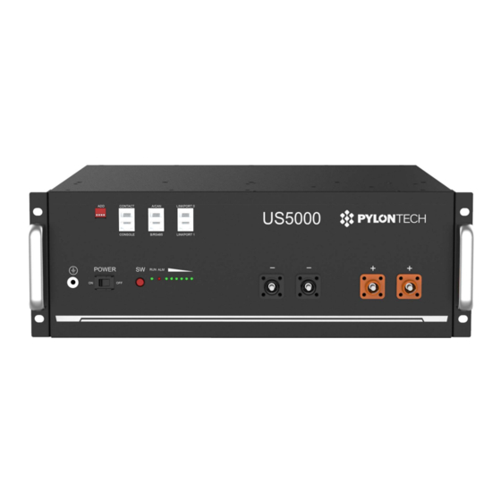
3.3 Equipment interface instruction US5000 front panel US5000-B front panel Breaker (for US5000-B) Parameter: type C, rated voltage 60V/DC, rated current 125A, Icu: 10kA. Standard reference: UL1077, IEC60947-2. ON: power terminals connect with battery. OFF: power terminals disconnect with battery. - Page 13 Reminding When breaker released for protection, check the root cause of current surge and cable connection between battery and inverter first. Then try to connect again. Power Switch ON: ready to turn on. OFF: power off. For storage or shipping. Start (SW) Turn on: press more than 0.5s to start the battery.
- Page 14 For instance: corresponding Dip1 Dip2 Dip3 Dip4 Status position of switch RS485:115200 CAN terminal resistance: connected RS485:9600 CAN terminal resistance: connected RS485: 115200 CAN terminal resistance: disconnected. Console For manufacturer or professional engineer to debug or service. Pin3 232-TX Pin4* +5~+12V for wake up Pin5* GND for wake up...
-
Page 15: Definition Of Rj45 Port Pin
500 Kbps. Recommended 120Ω. To inverter or upper battery. RS485 9600 or 115200 bps. Recommended 120Ω. To inverter or slave battery. Link Port 0, 1 For communication between multiple parallel batteries. Definition of RJ45 Port Pin A/CAN B/RS485 Pin1 These pins shall be NULL. If not, may influence communication Pin2 between BMS and inverter. - Page 16 LED Status Indicators Condition Power off Power on ● ● ● ● ● ● ● ● Idle/Normal ● Charge Show soc; highest LED flash, on 0.5s, off 0.5s ● Discharge ● Show soc ALR:●; Other LEDs are same as above. Alarm System ●...
-
Page 17: Safe Handling Of Lithium Batteries Guide
4. Safe handling of lithium batteries guide 4.1 Schematic diagram of solution 4.2 Label... -
Page 18: Tools
4.3 Tools Wire cutter Crimping modular plier Screwdriver NOTE Use properly insulated tools to prevent accidental electric shock or short circuits. If insulated tools are not available, cover the entire exposed metal surfaces of the available tools, except their tips, with electrical tape. 4.4 Safety gear It is recommended to wear the following safety gear when dealing with the battery. -
Page 19: Installation And Operation
5. Installation and operation 5.1 Package items Unpacking and check: 1) For battery module package: Battery Module 2 * 210mm 4AWG power cables 1 * 210mm RJ45 communication cable 1 * 1000mm 6AWG grounding cable... - Page 20 2) For External cable kits: NOTE: Power and communication cables connect to inverter belongs to an External Cable Kit, NOT include in battery carton box . They are in another extra small cable box. If there is anything missed, please contact dealer. 2 * 2000mm power cables (4 AWG, peak current capacity 120A, constant 100A) and communication cable for each energy storage system.
-
Page 21: Installation Location
5.2 Installation location Make sure that the installation location meets the following conditions: 1) The area is completely waterproof. 2) The floor is flat and level. 3) There are no flammable or explosive materials. 4) The ambient temperature is within the range from 0°C to 50°C. 5) The temperature and humidity are maintained at a constant level. -
Page 22: Installation Direction
5.3 Installation Direction NOT allowed: Upside down Sidelong Sidelong Recommended: Note Caution: Do not stack modules together directly. Caution: Make sure there is holder for more than 40kg weight at bottom of each module. Installed only rely on two handles is NOT allowed. -
Page 23: Grounding
5.4 Grounding Grounding cables shall be 6AWG or higher yellow-green cables. After connection, the resistance from battery grounding point to Ground connection point of room or installed place shall smaller than 0.1Ω. 1) based on metal directly touch between the module’s surface and rack’s surface. -
Page 24: Put Into Cabinet Or Rack
5.5 Put into cabinet or rack * External cabinet not provided by Pylontech. Scope of Product Certification does not include external cabinets. Put battery modules into cabinet and connect the cables: 1) Put the battery into the cabinet. 2) Drive the 4 pcs screws. -
Page 25: Put Into Bracket
5.6 Put into bracket 1) Put the battery into 2 pcs of bracket. 2) Use 4 location holes, stack the batteries together. And connect the 4 locker together. 3) Maximum 3 in stack. -
Page 26: Suitable Disconnection Device
NOTE After installation, do not forget to register online for full warranty: http://www.pylontech.com.cn/service/support Caution 1) For Australian market, an overcurrent and disconnection device that isolates all live conductors (positive and negative) is required between the battery system and the inverter 2) In Australia installations should be conducted in accordance with AS/ NZS 3000 and AS/NZS 5139. -
Page 27: Power On
5.8 Power on Double check all the power cable and communication cable between batteries and between battery and inverter. Switch ON the disconnection device between battery and inverter if available. For US5000-B: Switch ON all modules` breaker first. For US5000 and US5000-B: 1) Switch on all the battery modules: 2) The one with empty Link Port 0... -
Page 28: Power Off
3) Press the red SW button of master battery to power on, all the battery LED light will be on one by one from the Master battery: Note: 1) After the battery module powered on, the soft-start function takes 3sec to active. -
Page 29: Multi-Group Mode
Multi-group mode 5.10 Connect power cable first: 1) each pair of cable hold max 100A constant current Connect enough pairs of cable based on calculation of system current. 2) For Australian market, an overcurrent and disconnection device that isolates all live conductors (positive and negative) is required between the battery system and the inverter By RS485: DO NOT need LV-HUB. - Page 30 By CAN: 1) connect power cable of LV-HUB. 2) Connect communication cable follow the picture. the cable from master battery to LV-HUB, is recommended to use: WI0SCAN30RJ1 or cable with pin 1~3 empty. 3) Make sure all dipswitch of master batteries is 0000, then turn ON batteries. 4) After all batteries running and buzzer of master battery in group1 rings 3 times.
-
Page 31: Trouble Shooting
6. Trouble shooting Communication related problem Unable to communicate with inverter on compatible list. Possible conditions: 1) RS485: baud rate. Check the dip switch1, set to correct one, and restart. All master battery shall be the same. 2) CAN: terminal resistance. Check the dip switch2, set to 0 and retry. 3) CAN: pin. - Page 32 Solution: to move battery to the normal operating temperature range between 0°C and 50°C. c) Current: If current exceeds 90A, battery protection will turn on. Solution: Check whether current is too large or not, if it is, change the settings on power supply side. d) High Voltage: If charging voltage above 54V, battery protection will turn on.
- Page 33 Check the communication between battery system and inverter whether established or not; Check the ADD switch on battery module whether is set correctly or not; Under this condition, the BMS remains functional without damage. Just leave the module switched OFF and wait for the battery voltage drop down naturally(15mins) then restart.
-
Page 34: Emergency Situations
If detect the battery cell is catching fire, firstly cut off the external power source. Then use vast of water for suppression. After fire suppressed, soaking battery within water and contact Pylontech or an authorized dealer. If detect the cabling or other components (not battery cell) is catching fire. -
Page 35: Remarks
8. Remarks Recycle and disposal. In case a battery (normal condition or damaged) needs disposal or needs recycling, it shall follow the local recycling regulation (i.e. Regulation (EC) Nº 1013/2006 among European Union) to process, and using the best available techniques to achieve a relevant recycling efficiency. - Page 36 Pylon Technologies Co., Ltd. No. 73, Lane 887, ZuChongzhi Road, Zhangjiang Hi-Tech Park Pudong, Shanghai 201203, China T+86-21-51317699 | +86-21-51317698 service@pylontech.com.cn www.pylontech.com.cn...
Need help?
Do you have a question about the US5000 Series and is the answer not in the manual?
Questions and answers