Advertisement
Advertisement
Table of Contents

Subscribe to Our Youtube Channel
Related Manuals for Pylontech US Series


Summary of Contents for Pylontech US Series
- Page 1 PYLONTECH Training Course...
- Page 2 Why Energy Storage? Why Lithium-ion Phosphate? Why Pylontech?
- Page 3 PYLONTECH US series / Phantom-S PRODUCT TRAINING...
- Page 4 C O N T E N T UNPACKING INSTALLATION POWER ON/OFF MULTIPLE STRINGS TROUBLE SHOOTING...
-
Page 5: Product Parameter
Product Parameter... - Page 6 UNPACKING...
-
Page 7: Checking List
CHECKING LIST 1) For battery module package: One pair of power cables,one communication cable,one grounding cable, user manual and warranty card. - Page 8 CHECK LIST 2) For battery system connects to inverter:( extra small cable box) One pair of power cables and one communication.
-
Page 9: Installation
INSTALLATION... - Page 10 BEFORE YOU START • Installation Manual • Location & Environment • Tools & Accessories • Compatible Inverter...
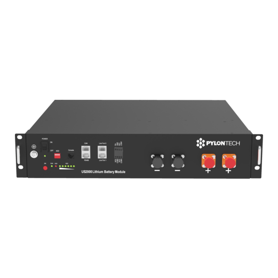
- Page 11 INSTALLATION 1) Battery Module Front Interface:...
- Page 12 INSTALLATION 2) Connection: The one with empty Link Port 0 is the Master Battery Module, Which is connected to the Inverter,others are slaves. 1 master battery configure with maximum 7 slave batteries in one string.
- Page 13 INSTALLATION 5kW < Power < 10kW Power ≤ 5kW...
-
Page 14: Power On/Off
POWER ON/OFF... - Page 15 POWER ON/OFF 1) Power on: Double check all the power cable and communication cable. 1.Switch ON all the battery modules by hard switch. 2.Press the Red SW button of master battery(≥ 0.5 sec).
- Page 16 POWER ON/OFF 1) Power on:...
- Page 17 POWER ON/OFF 2) Power OFF: Double check all the power cable and communication cable. 1.Press the Red SW button of master battery(≥0.5 sec). 2.Switch OFF the battery modules by the hard switch.
-
Page 18: Multiple Strings
MULTIPLE STRINGS... - Page 19 LV-HUB 1) LV-HUB Front Interface:...
- Page 20 Multiple Strings 1) Cables Connection Diagram for RS485: To Inverter...
- Page 21 LV-HUB 1) Cables Connection Diagram for CAN: To Inverter...
-
Page 22: Address Assignment
Address Assignment 1) Dips switch setting: ADD Switch: 4 ADD switches, Dip1 to define different baudrate (ON = 9,600, OFF = 115,200). Dip2 ~4 to definite the group`s address (ON is 1, OFF is 0). The settings will be active only after restart the battery. - Page 23 LV-HUB TIPS: ⚫ Each battery group can configure maximum 8pcs battery modules. ⚫ LV-Hub-A configures maximum 5 group batteries.; ⚫ When each battery group’s current is >120A, this battery group must configure 2 pair external power cables like the diagram. ⚫...
-
Page 24: Troubleshooting
TROUBLE SHOOTING... - Page 25 Check List ⚫ Environment & Status ⚫ Wiring Connection ⚫ Voltage Measurements ⚫ Power On/Off...
-
Page 26: Warranty Card
Warranty Card... - Page 27 Battery View ⚫ Monitoring ⚫ Firmware Upgrade ⚫ Acquire Historical Log ⚫ Setting Change...
- Page 28 Sample Log File...
- Page 29 THANKS For any questions, please contact: service@pylontech.com.cn...
Need help?
Do you have a question about the US Series and is the answer not in the manual?
Questions and answers