Advertisement
Table of Contents
- 1 Table of Contents
- 2 Introduction
- 3 Hub
- 4 Ports
- 5 Definition of Rj45 Port Pin
- 6 Led Indicators Instructions
- 7 Operation
- 8 Protocol
- 9 Cables Connection for Us2000/Us3000 under Rs485 or Canbus
- 10 Cables Connection for Rs485
- 11 Cables Connection for Can (Single Hub)
- 12 Cables Connection for Us2000C/Us3000C/Up5000/Us5000 under Canbus
- 13 Cables Connection for Multiple Hubs under Canbus
- 14 Annex 1: Cables Connection for Us2000/Us3000 under Rs485
- Download this manual
Advertisement
Table of Contents

Related Manuals for Pylontech LV-HUB


Summary of Contents for Pylontech LV-HUB
- Page 1 Communication HUB LV-HUB Product Manual Information Version: SD21HB01011202...
-
Page 3: Table Of Contents
This manual introduces LV-Hub from Pylontech. LV-Hub is a communication hub for US2000/US3000 Lithium-Ion Phosphate Battery storage system. Please read this manual before you install the battery and follow the instruction carefully during the installation process. CONTENT INTRODUCTION............................ 1 LV-HUB ..............................1 2.1 PORTS:.............................. - Page 4 ANNEX 2: CABLES CONNECTION FOR US2000/US3000 UNDER CAN ............ 12 ANNEX 3: CABLES CONNECTION FOR CAN (MULTI HUB) ............... 13 ANNEX 4: CABLES CONNECTION FOR US2000C/US3000C/UP5000/US5000 UNDER CANBUS ... 14...
-
Page 5: Introduction
1. Introduction LV-Hub is the CAN/RS485 communication hub for multiple 48V battery groups in parallel connection. Fit Description: US2000 / US3000 / Phantom-SA / US1800. 2. LV-Hub-A Item Parameter Operating voltage range 48 Vdc Communication interface CAN/RS485 System Consumption Size... -
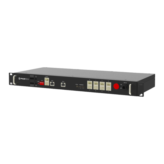
Page 6: Ports
STATUS Please see 2.3. Shows linked in battery group quantity with NUMBER/BIN 1-4 binary code. Please see 2.3. 9~16 RJ45 0; 1; 2; 3; 4; 5; 6; 7. Only uses 0~5. Please see 3.2. Switch ON/OFF Turns the LV-HUB ON/OFF. -
Page 7: Definition Of Rj45 Port Pin
Part Silk-screen Function Power supply: take 48VDC power from outside (from AC/DC 48VDC input 48V DC adaptor). 2.2 Definition of RJ45 Port Pin CAN OUT RS485 RS232 Pin CANH CANL RS485A RS485B... -
Page 8: Led Indicators Instructions
2.3 LED Indicators Instructions ● Only the HUB is turned ON, it lights once. No battery connected or at least one group is off line. When Status ● battery group is reduced it will alarm (in red), but when battery group is added in it will no alarm. Green flash;... -
Page 9: Operation
3.2 Cables Connection for US2000/US3000 under RS485 or CANBUS. 3.2.1 Cables Connection for RS485 Each battery group can configure maximum 8pcs US2000B Plus or 8pcs US3000. LV-Hub-A configures maximum 5 group batteries. RS485 communication needn’t additional cable and power just a simple hub is enough. -
Page 10: Cables Connection For Can (Single Hub)
The details of ADD Switch setting also can see the menu of battery. 3.2.2 Cables Connection for CAN (single HUB) Each battery group can configure maximum 8pcs US2000B Plus or 8pcs US3000. LV-Hub-A configures maximum 5 group batteries. - Page 11 When each battery group’s current is >120A, this battery group must configure 2 pair external power cables like the diagram. The details of ADD Switch setting also can see the menu of battery. When using with SMA SUNNY ISLAND, the ADD on HUB(or master HUB if there are multiple HUBs) must be 000011(for B14V0105 presenting on product label) or 000101 (for B14V0106 presenting on product label).
-
Page 12: Cables Connection For Us2000C/Us3000C/Up5000/Us5000 Under Canbus
5) After all batteries running and buzzer of master battery in group1 rings 3 times. Means all groups are online. 6) Change the dip switch of master battery in group1 to X1XX. Then connect communication cable between LV-HUB and master battery in group 1. 7) Then turn ON LV-HUB. - Page 13 *Below communication cable shall has first 3 pin NULL or use WI0SCAN30RJ1 cable inside external cable kits: Between Group 1 Master Battery A/CAN to LV-HUB Port 1. Note: When using US2000C/US3000C/UP5000/US5000, the multiple group connection under RS485 communication DONOT require a LV-HUB. The wiring diagram please refer to the corresponding battery model operation manual.
-
Page 14: Cables Connection For Multiple Hubs Under Canbus
3.4 Cables Connection for Multiple HUBs under CANBUS. In above picture, all communication cable connect in between shall be 8 pin direct-pin cable. -
Page 15: Annex 1: Cables Connection For Us2000/Us3000 Under Rs485
Annex 1: Cables Connection for US2000/US3000 under RS485... - Page 16 Annex 2: Cables Connection for US2000/US3000 under CAN...
- Page 17 Annex 3: Cables Connection for CAN (multi HUB)
- Page 18 Annex 4: Cables Connection for US2000C/US3000C/UP5000/US5000 under CANBUS...
- Page 20 Pylon Technologies Co., Ltd. No. 73, Lane 887, ZuChongzhi Road, Zhangjiang Hi-Tech Park Pudong, Shanghai 201203, China T+86-21-51317699 | +86-21-51317698 service@pylontech.com.cn www.pylontech.com.cn...
Need help?
Do you have a question about the LV-HUB and is the answer not in the manual?
Questions and answers