Table of Contents
Advertisement
Quick Links
Lithium-Iron Phosphate Battery
US2000 (Version B) Product Manual
Information Version: 1.0
Pylon Technologies Co., Ltd.
No. 73, Lane 887, ZuChongzhi Road, Zhangjiang Hi-Tech Park
Pudong, Shanghai 201203, ChinaZip Code: 201203
Tel: 021-51317697
Fax: 021-51317698
Email:
service@pylontech.com.cn
Website:
http://www.pylontech.com.cn
1 / 19
16BISV0903
Advertisement
Table of Contents

Related Manuals for Pylontech US2000B+


Summary of Contents for Pylontech US2000B+
- Page 1 Lithium-Iron Phosphate Battery US2000 (Version B) Product Manual Information Version: 1.0 Pylon Technologies Co., Ltd. No. 73, Lane 887, ZuChongzhi Road, Zhangjiang Hi-Tech Park Pudong, Shanghai 201203, ChinaZip Code: 201203 Tel: 021-51317697 Fax: 021-51317698 Email: service@pylontech.com.cn Website: http://www.pylontech.com.cn 1 / 19 16BISV0903...
-
Page 2: Table Of Contents
This manual introducesUS2000 (VERSION B) from Pylontech. Please read this manual before youto install the battery and follow the instruction carefully during the installation process. Any confusion, please contact Pylontech immediately for advice and clarification. Contents 1. INTRODUCTION ............................... 3 1.1 features: .............................. -
Page 3: Introduction
US2000 (VERSION B) lithium iron phosphate battery is one of new energy storage products developed and produced by Pylontech, it can be used to support reliable power for various types of equipments and systems. US2000 (VERSION B) is especially suitable for application scene of high power, limited installation space, restricted load-bearing and long cycle life. -
Page 4: Specifications
1.2 Specifications Basic Parameters US2000 (VERSION B) Nominal Voltage(V) Nominal Capacity(Ah) Dimension(mm) 440*410*89 Weight(Kg) Discharge Voltage(V) 45 ~ 54 Charge Voltage(V) 52.5 ~ 54 Peak Discharge Power(W) 5KW@1Min Peak Charge Power(W) 5KW@1Min RS232,RS485,CAN Communication 0℃~50℃ Charge Working Temperature -10℃~50℃ Disharge -20℃~60℃... -
Page 5: Equipment Interface Instruction
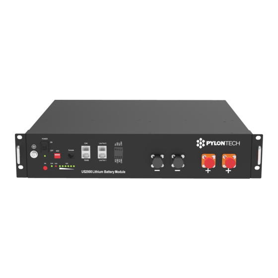
1.3 Equipment Interface Instruction This section details the front and back panel of the interface functions. US2000 (VERSION B) Product Front Interface Power Switch Power Switch: to turn ON/OFF the whole battery BMS standby, no power output. RUN light: to show the Power Switch is ON, and the BMS has electricity (No power). Start Start Button: to start the battery module, Power output ready. -
Page 6: Definition Of Rj45 Port Pin
R485 Communication Terminal: (RJ45 port) follow RS485 protocol, for output batteries information. Link Port 0, 1 Link Port 0, 1 Communication Terminal: (RJ45 port) follow RS485 protocol, for communication between multiple parallel batteries. Definition of RJ45 Port Pin RS485Pin CAN Pin RS485B RS485A CANH... -
Page 7: Led Indicators Instructions
RUN Lamp (No.6 Figure 2-1): green, long lighting when charging and flash when discharging; ALM Lamp (No.7 Figure 2-1 7): red, flashes when alarm and long bright if equipment failure or protected; Battery capacity indicator (No.8 Figure 2-1): 6 green lamps, each light represent 16.6% capacity. -
Page 8: Safe Handling Of Lithium Batteries Guide
2. Safe handling of lithium batteries Guide 2.1 Schematic Diagram of Solution 2.2 Explanation of Symbol 2.3 Tools The following tools are required to install the battery pack Wire cutter Crimping Modular Plier Screw Driver 8 / 19 16BISV0903... -
Page 9: Safety Gear
NOTE Use properly insulated tools to prevent accidental electric shock or short circuits. If insulated tools are not available, cover the entire exposed metal surfaces of the available tools, except their tips, with electrical tape. 2.4 Safety Gear It is recommended to wear the following safety gear when dealing with the battery pack Insulated gloves Safety goggles Safety shoes... -
Page 10: Installation
3. Installation 3.1 Package Items Unpacking and check the Packing List 1) For battery module package: Two power cables and one communication cable for each battery package: Grounding cable : 2) For battery system connects to inverter: Two long power cables (current capacity 120A) and one communication cable for each energy storage system: 10 / 19 16BISV0903... -
Page 11: Installation Location
NOTE These three long cables are NOT in battery package, they are in another extra small cable box. If there is anything missed please contact dealer. 3.2 Installation Location Make sure that the installation location meets the following conditions: The area is completely water proof. ... - Page 12 Put the battery into the cabinet; Drive the 4 pcs screws; Connect the cables between battery modules Connect the cables to inverter B. Power On Double check all the power cable and communication cable. (1) Switch power on Switch on all the battery modules and the green LED light below will be on: 12 / 19 16BISV0903...
- Page 13 emptyLink Port 0 is the Master Battery Module, others are slaves: (2) The one with (3) Press the red button of master battery to power on, all the battery LED light will be on one by one from the Master battery: If all the battery LED lights on, and then off, which means the battery system is good and working.
- Page 14 C. Installation with bracket: 1. Dismantle the 2 tabs on the battery. Dismantle 8 screws. 14 / 19 16BISV0903...
- Page 15 Aim at the 4 pare of Location Pin and Location Hole, stack the batteries together. And hasp the 4 agraffes together. Maximum 4 batteries can be athwart stacked: 15 / 19 16BISV0903...
- Page 16 Power Communication Cables Cables One or two batteries can be sidelong stacked: Cables connection and batteries system start are same as cabinet installation. NOTE After installation, do not forget to register online for full warranty: www.pylontech.com.cn/service/registration 16 / 19 16BISV0903...
-
Page 17: Safety Precautions
5) In case of fire, only dry powder fire extinguisher can be used, liquid fire extinguishers are prohibited; 6) Please do not open, repair or disassemble the battery except staffs from Pylontech or authorized by Pylontech. We do not undertake any consequences or related responsibility which because of violation of safety operation or violating of design, production and equipment safety standards. -
Page 18: Trouble Shooting Steps
If the battery external switch is ON, the RUN light is flashing, and the external power supply voltage is 48V or more, the battery still unable to turn on, please contact Pylontech. 2) The battery can be turned on, but red light is lighting, and cannot charge or discharge. If the red light is lighting, that means system is abnormal, please check values as following: a) Temperature: Above 50℃... -
Page 19: Emergency Situations
Damaged batteries are dangerous and must be handled with the utmost care. They are not fit for use and may pose a danger to people or property. If the battery pack seems to be damaged, pack it in its original container, and then return it to Pylontech or an authorized dealer. NOTE Damaged batteries may leak electrolyte or produce flammable gas.
Need help?
Do you have a question about the US2000B+ and is the answer not in the manual?
Questions and answers