Pylontech US3000C Operation Manual
Rechargeable li-ion battery
Hide thumbs
Also See for US3000C:
- Product presentation (43 pages) ,
- Product manual (20 pages) ,
- Manual (15 pages)

Related Manuals for Pylontech US3000C


Summary of Contents for Pylontech US3000C
- Page 1 Rechargeable Li-ion Battery US3000C Operation Manual Information Version: 1.1 20CQSV0902...
-
Page 3: Table Of Contents
This manual introduces US3000C from Pylontech. Please read this manual before you to install the battery and follow the instruction carefully during the installation process. Any confusion, please contact Pylontech immediately for advice and clarification. Safety Precautions 1.1 Before Connecting 1.2 In Using... -
Page 5: Safety Precautions
1. Safety Precautions Reminding 1) It is important and necessary to read the user manual carefully (in the accessories) before installing or using battery. Failure to do so or to follow any of the instructions or warnings in this document can result in electrical shock, serious injury, or death, or can damage battery, potentially rendering it inoperable 2) If the battery is stored for long time, it is required to charge them every six... -
Page 6: Before Connecting
Please do not open, repair or disassemble the battery except staffs from Pylontech or authorized by Pylontech. We do not undertake any consequences or related responsibility which because of violation of safety operation or violating of design, production and equipment safety standards. -
Page 7: Introduction
2. Introduction US3000C lithium iron phosphate battery is the new energy storage products developed and produced by Pylontech, it can be used to support reliable power for various types of equipment and systems. US3000C has built-in BMS battery management system, which can manage and monitor cells information including voltage, current and temperature. -
Page 8: Specification
discharge 14) Small size and light weight, standard of 19-inch embedded designed module is comfortable for installation and maintenance 15) Compatible with the US2000C, US3000, and US2000. 2.2 Specification... - Page 9 Basic Parameters US3000C Nominal Voltage (V) Nominal Capacity (Wh) 3552 Usable Capacity (Wh) 3374.4 Dimension (mm) 442*420*132 Weight (Kg) Discharge Voltage (V) 44.5 ~ 53.5 Charge Voltage (V) 52.5 ~ 53.5 Recommend Charge/Discharge Current (A) Max. Charge/Discharge Current (A) Peak Charge/Discharge Current (A)
-
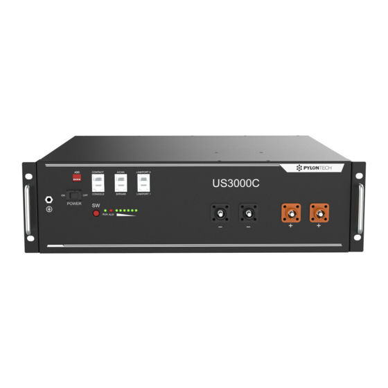
Page 10: Equipment Interface Instruction
2.3 Equipment interface instruction Power Switch ON: ready to turn on. OFF: power off. For storage or shipping. Start Turn on: press more than 0.5s to start the battery module Turn off: press more than 0.5s to turn off the battery. Green LED lighting to show the battery running status Alarm Red LED flashing to show the battery has alarm;... - Page 11 Pin3 232-TX Pin4* +5~+12V for wake up Pin5* GND for wake up Pin6 232-RX Pin8 232-GND *Wake up signal shall ≥0.5Sec, current between 5~15mA. After send wake up signal, the voltage shall disappear for normal operation. Contact Pin1 Input, passive signal. On: turn off battery. Off: normal. Pin2 Pin3 Output1.
-
Page 12: Definition Of Rj45 Port Pin
Definition of RJ45 Port Pin A/CAN B/RS485 Pin1 Shall be NULL. If not, may influence BMS function. Pin2 Pin3 Pin4 CAN-H CAN-H (single group) Pin5 CAH-L CAN-L (single group) Pin6 CAN-GND CAN-GND (single group) Pin7 485A 485A Pin8 485B 485B Power Terminals Power cable terminals: there are two pair of terminals with same function, one connects to equipment, the... - Page 13 ● flash, on: 0.3s; off: 3.7s ●/● flash, on:0.5s; off: 1.5s BMS basic function Protection and alarm Management and monitor Charge/Discharge End Cells Balance Charge Over Voltage Intelligent Charge Model Discharge Under Voltage Charge/Discharge Current Limit Charge/Discharge Over Current Capacity Retention Calculate High/Low Temperature(cell/BMS) Administrator Monitor Short Circuit...
-
Page 14: Safe Handling Of Lithium Batteries Guide
3. Safe handling of lithium batteries guide 3.1 Schematic diagram of solution 3.2 Danger label... -
Page 15: Tools
3.3 Tools Wire cutter Crimping modular plier Screwdriver NOTE Use properly insulated tools to prevent accidental electric shock or short circuits. If insulated tools are not available, cover the entire exposed metal surfaces of the available tools, except their tips, with electrical tape. 3.4 Safety gear It is recommended to wear the following safety gear when dealing with the battery pack... -
Page 16: Installation And Operation
4. Installation and operation 4.1 Package items Unpacking and check the Packing List 1) For battery module package: Two power cables and one communication cable for each battery package: Grounding cable: 2) For battery system connects to inverters: Two long power cables (current capacity 120A, constant 100A) and one communication cable for each energy storage system: NOTE These three cables are belonging to External Cable Kit, NOT in battery... -
Page 17: Installation Location
3000 4.2 Installation location Make sure that the installation location meets the following conditions: The area is completely water proof The floor is flat and level. There are no flammable or explosive materials. The ambient temperature is within the range from 0°C to 50°C. The temperature and humidity is maintained at a constant level. - Page 18 Caution If the ambient temperature is out of the operating range, the battery stops operating to protect itself. The optimal temperature range for the battery pack to operate is 10°C to 40°C. Frequent exposure to harsh temperatures may deteriorate the performance and life of the battery.
-
Page 19: Grounding
4.3 Grounding Grounding cables shall be 10AWG or higher yellow-green cables. After connection, the resistance from battery grounding point to Ground connection point of room or installed place shall smaller than 0.1Ω. 1) based on metal directly touch between the module’s surface and rack’s surface. -
Page 20: Put Into Cabinet Or Racks
4.4 put into cabinet or racks Put battery modules into cabinet and connect the cables: Put the battery into the cabinet Drive the 4 pcs screws Connect the cables between battery modules... - Page 21 Connect the cables to inverter...
-
Page 22: Put Into Bracket
4.5 Put into bracket 1) Dismantle the 2 holders of battery. - Page 23 2) Put the battery into 2 pcs of bracket. 3) Use 4 location holes, stack the batteries together. And connect the 4 locker together.
- Page 24 4) Maximum 4 in stack. NOTE After installation, do not forget to register online for full warranty: http://www.pylontech.com.cn/service/support Caution 1) a suitable breaker between battery system and inverter is required. 2) all the installation and operation must follow local electric standard.
-
Page 25: Power On
4.6 power on Double check all the power cable and communication cable. 3) Switch on all the battery modules: 4) The one with empty Link Port 0 is the Master Battery Module, others are slaves (1 master battery configure with maximum 15 slave batteries): 5) Press the red SW button of master battery to power on, all the battery LED light will be on one by one from the Master battery:... -
Page 26: Power Off
Note: 1) After the battery module powered on, the soft-start function takes 3sec to active. After soft-starts battery ready to output high power. 2) During capacity expansion or replacement, when parallel different SOC/voltage of module together, please maintain the system in idle for ≥15mins or till the SOC LEDs becomes similar(≤1dot difference) before normal operation. -
Page 27: Multi-Group Mode
4.8 Multi-group mode By RS485: DO NOT need LV-HUB. Connect power cable first: each pair of cable hold max 100A constant current. Connect enough pairs of cable based on calculation of system current. Suitable protection breaker between battery system and inverter is required. - Page 28 By CAN: Connect power cable first: 1) each pair of cable hold max 100A constant current. Connect enough pairs of cable based on calculation of system current. 2) Suitable protection breaker between battery system and inverter is required. 3) connect power cable of LV-HUB 4) Make sure all dipswitch is X0XX, then turn ON batteries.
-
Page 29: Trouble Shooting
5. Trouble shooting. Problem determination based on Whether the battery can be turned on or not If battery is turned on, check the red light is off, flashing or lighting If the red light is off, check whether the battery can be charged/discharged or not. - Page 30 d) High Voltage: If charging voltage above 54V, battery protection will turn on. Solution: Check whether voltage is too high or not, if it is, to change the settings on power supply side. And discharge the module. e) Low Voltage: When the battery discharges to 44.5V or less, battery protection will turn on.
- Page 31 then try turn on the single module, without any cable connected. If no alarm, then it is reverse connection of cables. Switch off the module and contact your local distributor. MOSFAIL. Solution: Power off all battery and inverters. Disconnect breaker. Check the cable connection and disconnect all power cables.
-
Page 32: Emergency Situations
3) Wet Batteries If the battery pack is wet or submerged in water, do not let people access it, and then contact Pylontech or an authorized dealer for technical support. Cut off all power switch on inverter side. 4) Damaged Batteries Damaged batteries are dangerous and must be handled with the utmost care. -
Page 33: Remarks
7. Remarks Recycle and disposal In case a battery (normal condition or damaged) needs disposal or needs recycling, it shall follow the local recycling regulation (i.e. Regulation (EC) Nº 1013/2006 among European Union) to process, and using the best available techniques to achieve a relevant recycling efficiency. - Page 36 Pylon Technologies Co., Ltd. No. 73, Lane 887, ZuChongzhi Road, Zhangjiang Hi-Tech Park Pudong, Shanghai 201203, China T+86-21-51317699 | +86-21-51317698 service@pylontech.com.cn www.pylontech.com.cn...
Need help?
Do you have a question about the US3000C and is the answer not in the manual?
Questions and answers