
Subscribe to Our Youtube Channel
Related Manuals for Pylontech UP2500


Summary of Contents for Pylontech UP2500
- Page 1 PYLONTECH Rechargeable Lithium-Ion Battery UP2500 Product Manual Information version 2.0...
-
Page 3: Table Of Contents
......................... 3 2.2 Specifications ......................... 4 2.3 Equipment Interface Instruction ................... 5 UP2500 Product Front Interface ....................5 Definition of RJ45 Port Pin ......................5 Definition of RJ 1 1 Port Pin ........................5 LED Indicators Instructions ......................5 3. -
Page 4: Safety Precautions
1. Safety Precautions Reminding It is very important and necessary to read the user manual carefully (in the accessories) before installing or using battery. Failure to do so or to follow any of the instructions or warnings in this document can result electrical shock, serious... -
Page 5: In Using
In case of fire, only dry powder fire extinguisher can be used, liquid fire extinguishers are prohibited; Please do not open, repair or disassemble the battery except staffs from Pylontech or authorized by Pylontech. We do not undertake any consequences or related responsibility which because of violation of safety operation or violating of design, production and equipment safety standards. -
Page 6: Introduction
2. Introduction UP2500 lithium iron phosphate battery one of new energy storage products developed and produced by Pylontech, can be used to support reliable power for various types of equipments and systems. UP2500 is especially suitable application scene of high power, limited installation... -
Page 7: Specifications
2.2 Specifications • • • , r:rL , Ill:i titI j,(e1u1111:- Nominal Voltage (V) 25.6 Nominal Capacity (Wh) 2840 Usable Capacity (Wh) 2550 Dimension (mm) 442*420* Weight (Kg) 26.5 Discharge Voltage (V) 23.2 - 28.5 Charge Voltage (V) 28.2 - 28.5 Recommend Charge/Discharge Current (A) Max. -
Page 9: Equipment Interface Instruction
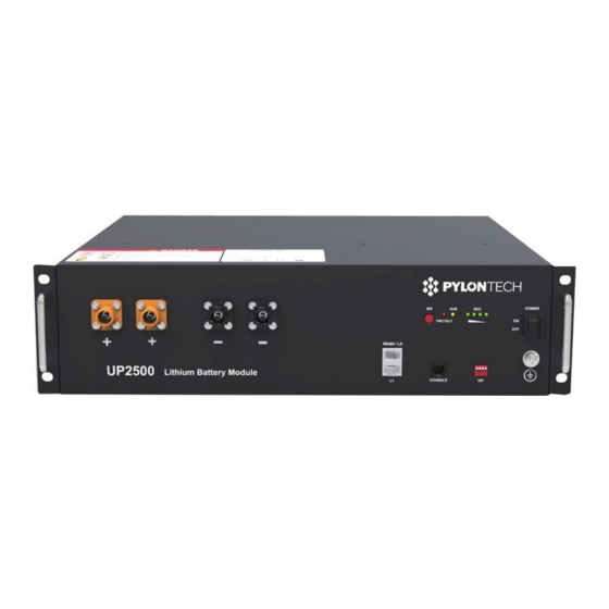
2.3 Equipment Interface Instruction This section details front panel of the interface functions. UP2500 Product Front Interface Power Switch Power Switch: turn ON/ OFF the battery standby, no power output. SOC light: 4 green LED show battery's current capacity. Alarm Alarm light: Y ELLOW LED falshing or lighting to show battery has alarm. - Page 10 LED Status Indicators Ifs important check the detailed alarm/protection definition follow the below table trouble-shooting and maintenance service. • • • • •••J1Ielllre111 HeJII f:IlB H:fA • • • • • All LED lighting until battery Turn off Power • •...
- Page 11 Start Start Button: press more than 2sec to Start/Off the battery module. ADD Switch ADD Switch: 4 ADD switches. Dipl definite different baud rate "OXXX" XXX" setup the baud rate setup bond rate 1 15200, and "1 9600. The setting will be active only after restart the battery. Every battery module needs change the dip switch to set RS485...
-
Page 12: Definition Of Rj45 Port Pin
Definition of RJ45 Port Pin When connect to host equipment, pin 1-5 should be NULL • lmi) ;J;1 '{,f RJ45 Port RS485A RJ45 Plug RS485B Definition RJ11 Port Pin • RJll Pori RJ11 Plug Power Terminals Power cable terminals: there are two pai r of terminals with same function, one lod<IMton... -
Page 13: Safe Handling Of Lithium Batieries Guide
3. Safe handling of lithium batteries Guide 3.1 Schematic Diagram of Solution Inverter Public Grid Battery Module 3.2 Explanation of Symbol * Do not disconnect or disassemble by non-professional personnel. * Do not drop, deform, impact, cut or spearing with a sharp object. * Do not place at a children or pet touchable area. -
Page 14: Tools
3.3 Tools The following tools required to install the battery pack ---- Crimping Modular Plier Wire cutter Screw Driver NOTE Use properly insulated tools to prevent accidental electric shock or short circuits. insulated tools are available, cover the entire exposed metal surfaces available tools,... -
Page 15: Installation
Grounding cable: 1000 ctnl ====n ======== Grounding cables use 1OAWG yellow-green cables. UP2500 modules' grounding is based on metal directly touch between the module's surface and rack's surface. If uses normal rack, make sure the paint at connection place of rack... -
Page 16: Installation Location
2) For battery system connects to inverter: Two long power cables (current capacity 120A) and one communication cable for each energy storage system: ..u@) 2000 .- ------- 3500 ---------. Plll 1D- - -. _. - - - -"1fi ' i 17iln'ii NOTE These three long cables are... -
Page 17: Installation
Installation Put battery modules i nto cabinet and connect the cables: 19UPSV0 501 13/19... - Page 18 To Inverter (1) Put the battery into the cabinet; Drive the screws; Connect cables between battery modules. If use Connect the cables to inverter 19UPSV050 14/19...
- Page 19 power cables' current capacity is battery string's current over this limit,it must 120A. configure 2 rs of external power cables to reach 240A 6 /19 19UPSV0 501...
-
Page 20: Power On
Power On Double check the power cable and communication cable. ) Switch power on Switch on all the battery modules: (2) The one with empty is the Master Battery Module, others are slaves ( master battery configure with maximum 19 slave batteries) . And then from Master Battery Module's RS485 to inverter:... - Page 21 • • • I f all the battery LED li ghts and then off,whi ch means the battery system is good and working. 19UPSV050 17/19...
-
Page 22: Trouble Shooting Steps
5. Trouble Shooting Steps Please always check the 'LED Indicators Instructions ' table for the detailed faulty definition before any trouble- shooting steps.5.1 Problem determination based Whether battery can be turned on or not; 2) If battery turned on,check the and yellow light is off, flashing or lighting;... -
Page 23: Emergency Situations
3) Wet Batteries If the battery pack wet or submerged in water, do not let people access it, and then contact Pylontech or authorized dealer technical support. 4) Damaged Batteries Damaged batteries are dangerous and must be handled with the utmost care. - Page 24 l9UPSV050 18/19...
- Page 25 PYLONTECH Pylon Technologies Co., Ltd. 73,Lane 887,ZuChongzhi Road,Zhangjiang Hi-Tech Park Pudong, Shanghai 201203, China +86-21-51317699 I +86-21-51317698 service@pylontech.com.cn www.pylontech.com. cn...
Need help?
Do you have a question about the UP2500 and is the answer not in the manual?
Questions and answers