Pylontech US2000 Operation Manual
Rechargeable li-ion battery
Hide thumbs
Also See for US2000:
- Product manual (22 pages) ,
- Manual (12 pages) ,
- Battery charging manual (2 pages)

Subscribe to Our Youtube Channel
Related Manuals for Pylontech US2000


Summary of Contents for Pylontech US2000
- Page 1 Rechargeable Li-ion Battery US2000 Operation Manual UL version Information Version: V1.0 L20BPSV0901...
-
Page 3: Table Of Contents
This manual introduces US2000 from Pylontech. Please read this manual before you to install the battery and follow the instruction carefully during the installation process. Any confusion, please contact Pylontech immediately for advice and clarification. Safety / Sécurité Introduction Features... -
Page 4: Safety / Sécurité
Sécurité Safety / The US2000 is operated by authorized person only. Read all safety instructions carefully prior to any work and observe them at all times when working on with the system. US2000 opéré uniquement par le personnel autorisé. Lisez attentivement toutes les instructions de sécurité... - Page 5 Symbol /Symbole Lethal voltage! Tension mortelle! Battery strings will produce high voltage DC power and can cause a lethal voltage and an electric shock. La batterie produira un courant continu à haute Danger tension et peuvent provoquer une tension mortelle Danger et un choc électrique.
- Page 6 Danger Batteries deliver electric power, resulting in burns or a fire hazard when they are short circuited, or wrongly installed. Les piles fournissent de l'énergie électrique, ce qui entraîne des brûlures ou un risque d'incendie lorsqu'elles sont court-circuitées ou mal installées. Lethal voltages are present in the battery terminals and cables.
- Page 7 Warning Do not open or deform the battery module; It is prohibited to disassemble the battery (QC tab removed or damaged) Ne pas ouvrir ou déformer le module de batterie; Il est interdit de démonter la batterie (languette QC retirée ou endommagée For battery installation, the installer shall refer to NFPA70 standard for operation.
- Page 8 Please ensured the electrical parameters of battery system are compatible to related equipment, such as charger, inverter or load. Make sure the settings on inverter are correct for US2000. If possible, check the communication between battery system and inverter is...
- Page 9 Caution before connecting Before installation, be sure to cut off the grid power and make sure the battery is in the turned-off mode Avant l'installation, assurez-vous de couper l'alimentation du réseau et assurez-vous que la batterie est éteinte Wiring must be correct, do not mistake the positive and negative cables, and ensure no short circuit with the external device Le câblage doit être correct, ne pas confondre les câbles positif et négatif, et éviter tout court-circuit avec l'appareil externe...
- Page 10 Il est interdit de connecter la batterie à une batterie de différent type Please do not open, repair or disassemble the battery except staffs from Pylontech or authorized by Pylontech. We do not undertake any consequences or related responsibility which because of violation of safety operation or violating of design, production and equipment safety standards Veuillez ne pas ouvrir, réparer ou démonter la batterie, à...
-
Page 11: Introduction
2. Introduction US2000 lithium iron phosphate battery is the energy storage products developed and produced by Pylontech, it can be used to support reliable power for various types of equipment and systems. US2000 has built-in BMS battery management system, which can manage and monitor cells information including voltage, current and temperature. -
Page 12: Specification
2.2 Specification Basic Parameters US2000 Nominal Voltage (V) Nominal Capacity (Wh) 2400 Usable Capacity (Wh) 2160 Dimension (mm) 440*410*89 Weight (Kg) 22.5 Discharge Voltage (V) 44.5 ~ 53.5 Charge Voltage (V) 52.5 ~ 53.5 Recommend Charge/Discharge Current (A) Max. Charge/Discharge Current (A) - Page 13 Depth of discharge (%) Configuration (max. in 1 battery group) 8pcs 0℃~50℃ Charge Working Temperature -10℃~50℃ Discharge Shelf Temperature -20℃~60℃ Protective class IP rating of enclosure IP20 Humidity 5 ~ 95%(RH) Certification TÜV / CE / UN38.3/UL Design life 10+ Years (25℃/77℉) Cycle Life >4,500 25℃...
-
Page 14: Equipment Interface Instruction
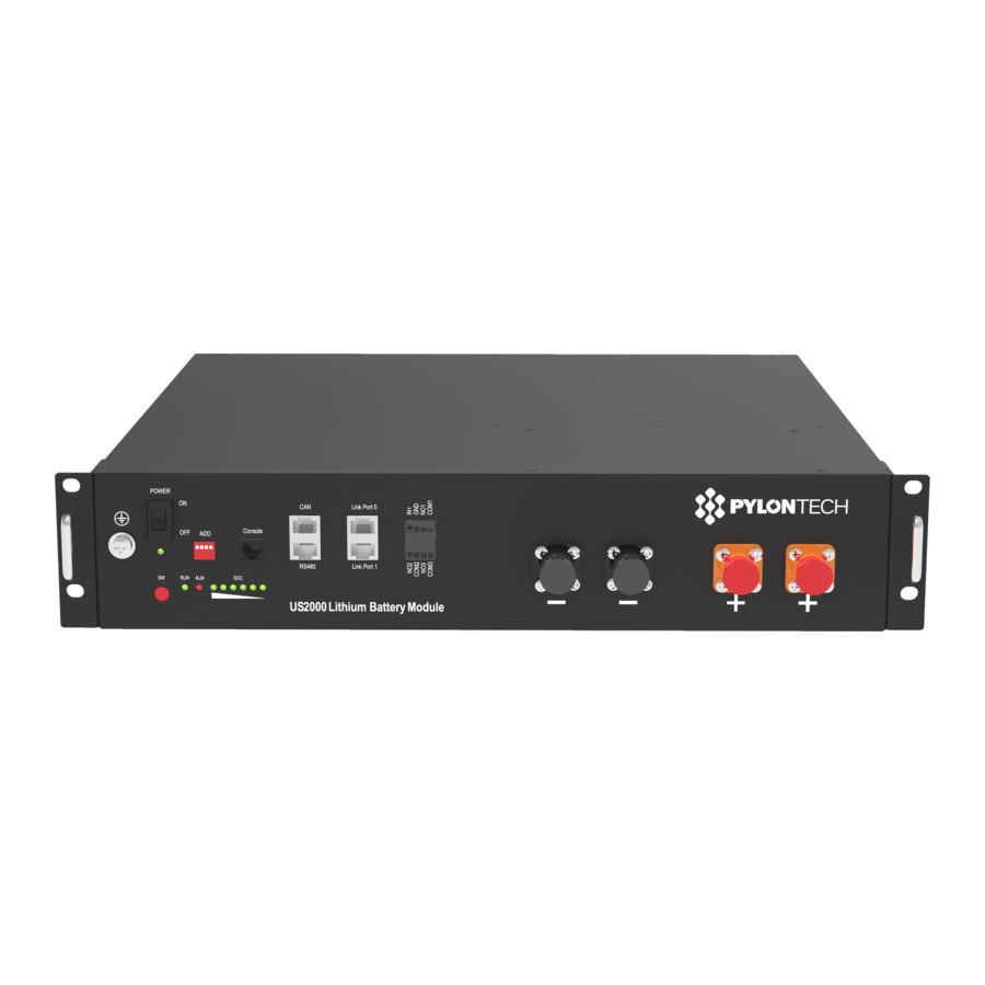
2.3 Equipment interface instruction Power Switch ON: ready to turn on. OFF: power off. For storage or shipping. Start Turn on: press more than 0.5s to start the battery module Turn off: press more than 0.5s to turn off the battery. Green LED lighting to show the battery running status Alarm Red LED flashing to show the battery has alarm;... - Page 15 Dip2 Dip3 Dip4 Group address number 0: single battery group 1: 1 battery group 2: 2 battery group 3: 3 battery group 4: 4 battery group 5: 5 battery group 6: 6 battery group 7: 7 battery group Console For manufacturer or professional engineer to debug or service. Pin 2: TXD.
-
Page 16: Definition Of Rj45 Port Pin
Definition of RJ45 Port Pin RS485 Pin1 RS485B Pin2 RS485A Pin3 Pin4 CAN H Pin5 CAN L Pin6 Pin7 RS485A(recommend) Pin8 RS485B(recommend) Power Terminals Power cable terminals: there are two pair of terminals with same function, one connects to equipment, the other one paralleling to other battery module for capacity expanding. - Page 17 Caution Must keep pressing the “Lock Button” while pulling out the power plug. Vous devez continuer à appuyer sur le « Bouton de verrouillage » tout en retirant la fiche d'alimentation. LED Status Indicators Condition Power off Power on ● ●...
-
Page 18: Safe Handling Of Lithium Batteries Guide
3. Safe handling of lithium batteries guide 3.1 Schematic diagram of solution 3.2 Danger label... -
Page 19: Tools
3.3 Tools Wire cutter Crimping modular plier Screwdriver NOTE Use properly insulated tools to prevent accidental electric shock or short circuits. If insulated tools are not available, cover the entire exposed metal surfaces of the available tools, except their tips, with electrical tape. 3.4 Safety gear It is recommended to wear the following safety gear when dealing with the battery pack... -
Page 20: Installation And Operation
4. Installation and operation 4.1 Package items Unpacking and check the Packing List 1) For battery module package: Two power cables and one communication cable for each battery package: Grounding cable: 1000 2) For battery system connects to inverters: Two long power cables (current capacity 120A, constant 100A) and one communication cable for each energy storage system: NOTE These three cables are belonging to External Cable Kit, NOT in battery package. -
Page 21: Installation Location
2000 2000 ≤3000 4.2 Installation location Make sure that the installation location meets the following conditions: The area is completely waterproof The floor is flat and level. There are no flammable or explosive materials. The ambient temperature is within the range from 0°C to 50°C. The temperature and humidity are maintained at a constant level. - Page 22 Caution If the ambient temperature is outside the operating range, the battery pack stops operating to protect itself. The optimal temperature range for the battery pack to operate is 0°C to 50°C. Frequent exposure to harsh temperatures may deteriorate the performance and life of the battery pack. Si la température ambiante est hors de la plage de température de service, la batterie cesse de fonctionner pour se protéger.
-
Page 23: Grounding
4.3 Grounding Grounding cables shall be 10AWG or higher yellow-green cables. After connection, the resistance from battery grounding point to Ground connection point of room or installed place shall smaller than 0.1Ω. 1) based on metal directly touch between the module’s surface and rack’s surface. -
Page 24: Put Into Cabinet Or Racks
4.4 put into cabinet or racks Put battery modules into cabinet and connect the cables: Put the battery into the cabinet Drive the 4 pcs screws Connect the cables between battery modules Connect the cables to inverter... -
Page 26: Put Into Bracket
4.5 Put into bracket 1) Dismantle the 2 holders of battery. - Page 27 2) Put the battery into 2 pcs of bracket. 3) Use 4 location holes, stack the batteries together. And connect the 4 lockers together.
- Page 28 4) Maximum 4 in stack.
-
Page 29: Power On
All the installation and operation must follow local electric standard. L’installation et l’opération doivent respecter les normes électriques locales. After installation, do not forget to register online for full warranty: http://www.pylontech.com.cn/service/support Warning The power cables’ current capacity is 120A max. If the battery string’s design... - Page 30 3) Press the red SW button of master battery to power on, all the battery LED light will be on one by one from the Master battery:...
-
Page 31: Power Off
Note: 1) During capacity expansion or replacement, when parallel different SOC/voltage of module together, please maintain the system in idle for ≥15mins or till the SOC LEDs becomes similar (≤1dot difference) before normal operation. 4.7 Power off 1) Turn external power source off. 2) Press red SW switch of master battery. - Page 32 By CAN:...
-
Page 34: Trouble Shooting
5. Trouble shooting. Problem determination based on Whether the battery can be turned on or not If battery is turned on, check the red light is off, flashing or lighting If the red light is off, check whether the battery can be charged/discharged or not. - Page 35 d) High Voltage: If charging voltage above 54V, battery protection will turn on. Solution: Check whether voltage is too high or not, if it is, to change the settings on power supply side. And discharge the module. e) Low Voltage: When the battery discharges to 44.5V or less, battery protection will turn on.
-
Page 36: Emergency Situations
3) Wet Batteries If the battery pack is wet or submerged in water, do not let people access it, and then contact Pylontech or an authorized dealer for technical support. Cut off all power switch on inverter side. 4) Damaged Batteries... - Page 37 They are not fit for use and may pose a danger to people or property. If the battery pack seems to be damaged, pack it in its original container, and then return it to Pylontech or an authorized dealer. Danger Damaged batteries may leak electrolyte or produce flammable gas.
-
Page 38: Remarks
7. Remarks Recycle and disposal In case a battery (normal condition or damaged) needs disposal or needs recycling, it shall follow the local recycling regulation to process, and using the best available techniques to achieve a relevant recycling efficiency. Maintenance 1) It is required to charge the battery at least once every 6 months, for this charge maintenance make sure the SOC is charged to higher than 90% 2) Every year after installation. - Page 40 Pylon Technologies Co., Ltd. No. 73, Lane 887, ZuChongzhi Road, Zhangjiang Hi-Tech Park Pudong, Shanghai 201203, China T+86-21-51317699 | +86-21-51317698 service@pylontech.com.cn www.pylontech.com.cn...
Need help?
Do you have a question about the US2000 and is the answer not in the manual?
Questions and answers