Table of Contents
Advertisement
Quick Links
Advertisement
Table of Contents

Related Manuals for GRASS VALLEY IQH4B


Summary of Contents for GRASS VALLEY IQH4B
- Page 1 IQH4B/IQRCG00 User Manual Issue 2 Revision 3 2022-06-30 www.grassvalley.com...
-
Page 2: Patent Information
Please read the following terms and conditions carefully. By using IQH4B/IQRCG00 documentation, you agree to the following terms and conditions. Grass Valley hereby grants permission and license to owners of IQH4B/IQRCG00 to use their product manuals for their own internal business use. Manuals for Grass Valley products may... -
Page 3: Important Safety Information
Use anti-static procedures, equipment and surfaces during servicing. The presence of this symbol in or on Grass Valley equipment means that it has been tested and certified as complying with applicable Underwriters Laboratory (UL) regulations and recommendations for USA. - Page 4 The presence of this symbol in or on Grass Valley equipment means that it has been tested and certified as complying with applicable Intertek Testing Services regulations and recommendations for USA/Canada. The presence of this symbol in or on Grass Valley product means that it complies with all applicable European Union (CE) directives.
- Page 5 IQH4B/IQRCG00 User Manual Cautions A caution indicates a possible hazard to equipment that could result in equipment damage. Observe the following cautions when operating or working on this equipment: • This equipment is meant to be installed in a restricted access location.
- Page 6 Replace the battery only with the same or equivalent type recommended by the manufacturer. Dispose of used batteries according to the manufacturer’s instructions. Before disposing of your Grass Valley equipment, please review the Disposal and Recycling Information at: http://www.grassvalley.com/assets/media/5692/Take-Back_Instructions.pdf...
- Page 7 IQH4B/IQRCG00 User Manual Mesures de sécurité et avis importants La présente section fournit des consignes de sécurité importantes pour les opérateurs et le personnel de service. Des avertissements ou mises en garde spécifiques figurent dans le manuel, dans les sections où ils s’appliquent. Prenez le temps de bien lire les consignes et assurez-vous de les respecter, en particulier celles qui sont destinées à...
- Page 8 électrique, de compatibilité électromagnétique et de conformité environnementale. Le symbole ci-contre sur un appareil Grass Valley ou à l’intérieur de l’appareil indique qu’il est conforme aux normes applicables en matière de sécurité laser. Avertissements Les avertissements signalent des conditions ou des pratiques susceptibles d’occasionner des blessures graves, voire fatales.
- Page 9 IQH4B/IQRCG00 User Manual • Ne pas utiliser cet appareil dans une atmosphère explosive. • Présence possible de courants de fuite. Un raccordement à la masse est indispensable avant la mise sous tension. • Après tout travail d’entretien ou de réparation, faites effectuer des contrôles de sécurité...
- Page 10 équivalent recommandé par le fabricant. Disposez des piles usagées conformément aux instructions du fabricant. Avant de vous séparer de votre équipement Grass Valley, veuillez consulter les informations de mise au rebut et de recyclage à: http://www.grassvalley.com/assets/media/5692/Take-Back_Instructions.pdf Précautions pour les écrans LCD et TFT Regarder l’écran pendant une trop longue période de temps peut nuire à...
-
Page 11: Environmental Information
Grass Valley believes this environmental information to be correct but cannot guarantee its completeness or accuracy since it is based on data received from sources outside our company. All specifications are subject to change without notice. -
Page 12: Lithium Batteries
Lithium Batteries Battery Warning Your Grass Valley equipment usually comes with at least one button battery located on the main printed circuit board. The batteries are used for backup and should not need to be replaced during the lifetime of the equipment. -
Page 13: Laser Safety - Fiber Output Sfp And Qsfp Modules Warning
IQH4B/IQRCG00 User Manual Laser Safety - Fiber Output SFP and QSFP Modules Warning LASER SAFETY The average optical output power does not exceed 0 dBm (1mW) under normal operating conditions. Unused optical outputs should be covered to prevent direct exposure to the laser beam. -
Page 14: Emc Standards
EMC Performance of Cables and Connectors Grass Valley products are designed to meet or exceed the requirements of the appropriate European EMC standards. In order to achieve this performance in real installations it is essential to use cables and connectors with good EMC characteristics. - Page 15 IQH4B/IQRCG00 User Manual SIGNAL/DATA PORTS For unconnected signal/data ports on the unit, fit shielding covers. For example, fit EMI blanking covers to SFP+ type ports; and fit 75 Ώ RF terminators to BNC type ports COAXIAL CABLES Coaxial cables connections (particularly serial digital video connections) shall be made with high-quality double-screened coaxial cables such as Belden 8281 or BBC type PSF1/2M and Belden 1694A (for 3Gbps).
-
Page 17: Table Of Contents
Table of Contents Patent Information ..............ii Copyright and Trademark Notice . - Page 18 Replacing a Fan Unit in a Live Environment ........33 Control Panels .
- Page 19 IQH4B User Manual Non-RollCall ..............52 Information Field(s) .
- Page 20 xviii...
-
Page 21: Introduction
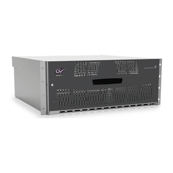
Introduction Unit Description IQH4B enclosures offer industry leading, high-density delivery of modular solutions. With up to 700W of module power available, this 4U rack unit enclosure accepts up to 20 modules, has dual redundant PSUs and in-service replaceable cooling fans. Analog reference signals can be distributed through the enclosures via 2 connections that can be independently selected by the installed modules. -
Page 22: Rear Panel View
Rear Panel View The IQH4B enclosure rear panel, without modules, is shown below. Features The IQH4B modular enclosure provides the following features: • 20 single or 10 double width modules (or any combination). • Integrated web browser based RollCall configuration and control. -
Page 23: Technical Specification
IEC320 C14 Power Consumption 1000 VA maximum Modules Power Dissipation IQH4B - 700 LU maximum Power is quoted in Load Units (LU) and is taken from the positive rail only Output +12 V and -7.5 V ± 5% Note that all modules have built-in power supply fuses... - Page 24 Mechanical Temperature Range 0 to 40°C operating, -20 to +85°C storage. A temperature and load sensitive cooling fan is fitted Humidity Range 10 to 85% (non condensing) Case Type 4U rack mounting aluminum case Dimensions W: 483 mm (445 mm behind rack location bracket) D: 485 mm H: 180 mm Weight...
-
Page 25: Installation
Note: When the unit is supplied fitted with two power supplies, ensure that both power supplies are installed correctly and power up successfully. Shipping Bar In order to prevent power supplies and modules from being dislodged in transit, the IQH4B is shipped with a retaining bar in place: Shipping Shipping bar fitted for transit Ensure that this shipping bar is removed before the enclosure is powered up. -
Page 26: Environment
Transporting the Enclosure If the enclosure is to be transported, ensure that the shipping bar is refitted in order to prevent internal components from shifting and causing damage. Environment Although constructed to meet the normal environmental requirements, it is important that there is a free flow of air at the front and rear to dissipate the heat produced during operation. -
Page 27: Front Panel Indicator
Each IEC connector supplies an independent feed of power to each of the two power supply modules as shown in the diagram above. As a redundancy option, the IQH4B enclosure can support two power supplies; however, only one is required. -
Page 28: Removing The Door
Removing the Door The IQH4B can be used without the door if required. To remove the door: 1 On the left side of the unit, looking from the front, locate the spring-loaded door release pin: Release 2 Push the pin in and disengage the door: 3 Move the door to the left to disengage the right-hand hinge, and remove the door. -
Page 29: Rollnet
IQH4B User Manual RollNet The BNC connector enables the unit to be connected to the RollCall network communications system. The RollCall system should be connected using a 75 Ohm “T” or “Y” piece, in a similar manner to an “Ethernet” system. Both extremities of the system must be terminated in 75 Ohms. -
Page 30: Front (Gateway Card) Controls And Leds
Front (Gateway Card) Controls and LEDs Front Panel connectors, controls and LEDs are provided by the Gateway Card, fitted into a dedicated slot in the IQH4B enclosure. Front Panel Connector This connector connects to the front panel and provides power to the LED on the front panel. -
Page 31: Leds
PSUs Gateway Card Module Slots 1 to 20 IQH4B enclosures are designed to accept one or two power supplies with independent IEC320 mains inlets. Individually, each PSU module is capable of powering the frame containing any combination of IQ-1B modules subject to the rules described in Configuration Rules on page 31. -
Page 32: Installing And Removing Power Supply Units
Note: Ensure that the mains power connection at the rear of the unit is removed before these operations are attempted. The IQH4B enclosure is provided with two PSUs as standard to allow dual redundant operation. Removing a Power Supply Unit To remove a power supply unit: 1 Open the front door panel. -
Page 33: Installing And Removing Modules
The IQH4B Enclosure has 700 Power Rating units available. The Power Ratings of each module should be added together and the total should not exceed 700PR units for the IQH4B. Modules that do not specify a Power Rating should use the total power figure as a power rating value. -
Page 34: Installing A New Module
7 Update the Power Rating table. Replacing a Module in a Live Environment Grass Valley recommends that the mains connections are removed before performing the operations described above. However, in a live environment this may not be possible, so the modules are designed to be removed and installed without switching the power off. -
Page 35: Replacement Of The Cooling Fan Assembly
User Manual Replacement of the Cooling Fan Assembly The cooling fan assembly is located on the rear panel of the IQH4B enclosure, and can easily be replaced without removing the rack from its mounting position or removing any cable connections. -
Page 36: Control Panels
Network bridges can be used to connect each network to up to 15 others, nested up to 4 levels, allowing tens of thousands of networks and millions of units to be joined together. IQH4B enclosures have two interface connections to the RollCall network: • RollNet 75 Ohm coaxial BNC running at 2.5 Mbps. -
Page 37: Ethernet Connections
Other IP devices can then connect to the enclosure via TCP/IP. An Ethernet device connected to a single IQ rack has access to all devices on the RollCall network. This interface can be used to connect a PC running RollCall. 75 Ohm Network IQH4B Box Computer 3U Box Ethernet... - Page 38 3 Open the Ethernet page and set IP network details as required; appropriate details should be available from local IT departments. See Ethernet on page 46 for more information. Restart the module to apply the changes. Recovering Mis-Configured Systems Although unlikely, it is possible to mis-configure the network IP settings and prevent connection to the Gateway, for instance by setting both Primary and Secondary LANs to use static IP addresses and then saving invalid values.
-
Page 39: Ip Bridging
IQH4B User Manual 4 To set a static IP address: • Open the appropriate file for the Ethernet interface to be configured, and eth?-dhcp ensure the value is set to 0. Save and close the file. • Open the appropriate... - Page 40 RollCall IP -> Connect to RollCall IP -> Connect to It is recommended that Only Accept This Address is checked at both ends to prevent other Gateways from establishing bridge connections, and that Connect Automatically is also checked at both ends, so the bridge is re-connected if it should become disconnected for any reason.
-
Page 41: Operation
O peration This section of the manual assumes that the IQH4B Enclosure has been installed in accordance with the instructions given in Chapter 3. It describes operation of the unit by means of the RollCall Control Panel software. To fully conform with EMC and Safety standards, modules must be correctly installed in the enclosure. -
Page 42: Line 3
Line 3 This show the inlet and exhaust temperatures of the enclosure in Celsius. Normally this would show, for example: • TEMP: 28C 27C 26C 25C where the first value of a pair is the inlet temperature, and the second is the exhaust temperature. -
Page 43: Setup
Click to power-cycle the Gateway. Power Usage This displays the maximum (MAX) allowable power available for modules. • IQH4B: 700 Load Units For example, MAX: 700LU This field also displays the current power usage (USED); this is the current total of all fitted modules’... -
Page 44: Information 1/2
Usage values per slot are available for viewing on the Slots pages, beginning on page • State: Displays OK if total power usage is below maximum, or WARN if the maximum has been exceeded. Information 1/2 These information fields may be edited to display any text required. For example, they could be used to provide further information on the Gateway card, such as rack position/building/group etc. -
Page 45: Report If Psus Missing
PSU. It is provided for system diagnostics, and should only be enabled on a temporary basis Comms Fail Restart These controls affect how the Gateway behaves in the event of communications failure. The controls are disabled by default. Enable only if instructed to do so by Grass Valley support. -
Page 46: Ethernet
Ethernet The Ethernet page enables networking functions to be configured. IMPORTANT - Unit IP Address/Subnet Mask/Gateway Address Defaults The IQ Gateway ships with the following default settings: • IP address: 192.168.151.1 • Subnet mask: 255.255.0.0 • Default IP Gateway: 0.0.0.0. Ethernet LAN 1 Primary/2 Secondary These sections allow static IP details to be set or DHCP to be activated for each LAN interface. -
Page 47: Rollcall Ip
Click Reset Counts to reset all packet counters to zero. Show IP Connections in Port Listing This control is not normally used. Enable it only if instructed to by Grass Valley support. Pass WAN Packets • SP_IAM: If this check box is enabled, then the Gateway will pass wide area I AM messages received on IP share links to the RollNet network, and over the IP Bridge (if connected). -
Page 48: Rollcall Ip Connections
• SP_TIME: If this is enabled, the Gateway will pass wide area TIME messages received on IP share links to the RollNet network, and over the IP Bridge (if connected). Note: The Gateway will always use the received time stamp, whether or not it passes it on. - Page 49 IQH4B User Manual from the primary and secondary connection addresses. Automatically selected if Alternate IP Enable is selected. • Alternate IP Enable: Select to allow both the primary and secondary IP addresses to be used. When selected Only Accept This Addr(s) is also automatically selected.
-
Page 50: Hyperion/Thumbnail Tcp Port
Hyperion/Thumbnail TCP Port The Gateway will accept Hyperion Thumbnail connections on this port number. The default is 2601. Thumbnailing is a Hyperion monitoring feature, allowing the viewing of thumbnail image streams, sourced from modules within the enclosure, on a remote PC. RollCall IP History The Gateway may reject IP connections if they do not match the client address set, or if the limit on IP connections has been reached. -
Page 51: Log Server
IQH4B User Manual Log Server The Log Server page allows the logging server to be configured. Log Server The log server to be used can be named by editing the text string in the text window. To enter/ modify the name of the log server, enter the new name in the text field and click S. To restore the default value, click P. -
Page 52: Accept Log Server Via Bridge
Accept Log Server via Bridge If this is selected, the Gateway will accept server packets via the bridge. Last Time Source Displays the address from which the last time packet was received. This can be useful when configuring complex networks. Only Accept Time from Log Server If this is selected, the Gateway will use time packets from the current log server only. -
Page 53: Slots 1-10, 11-20
IQH4B User Manual Slots 1-10, 11-20 The Slots pages allow each slot to be named and interrogated. Name The Name section displays the name and type of module fitted in the enclosure slot. See Examples of Slot Use on page 54 for more information. -
Page 54: Type
Type This displays the unique identifier of the module fitted in the slot. See Examples of Slot Use page 54 for more information. Bound Unit ID Preset Save Unit ID The following controls are provided: • Bound Unit ID: If a module matching the specified Bound Unit ID is fitted, the Gateway will display the user-specified name in the Name field (see Unit Type, above). -
Page 55: Information Field(S)
IQH4B User Manual Information Field(s) Information fields that may be edited by user to specify any information desired. See Examples of Slot Use on page 54 for more information. Preset Save Information 1 Information 2 For example, these could be used to name signal paths associated per card. Two fields are available, each allowing up to 19 characters to be displayed. -
Page 56: Examples Of Slot Use
• BadType: Module in slot is not expected type. • Extra: Module in slot but no module expected in this position. • --: No module fitted and no module expected in this slot. Examples of Slot Use Intentionally Empty Slot If a slot is intentionally left empty: •... -
Page 57: Control 1-10, 11-20
IQH4B User Manual Control 1-10, 11-20 The Control pages display information about the controllers for each slot. Update Packet Stats When the modules receive commands from control clients, the number of commands are counted. If the Update Packet Stats box is checked, the number of control packets from the currently-selected connected controller and from all connected controllers is shown to the right of the controller address. -
Page 58: Clear Packet Counts
Clear Packet Counts When Clear Packet Counts is clicked, all packet counters will be reset to zero. Slots 1 to 20 These sections display information about control clients. Active Front Panels and RollCall PC programs use a RollCall connection to control a module. RollTrack does not use a connection, it uses Blind Control. -
Page 59: Connections/Snmp
IQH4B User Manual Connections/SNMP The Connections/SNMP page provides information about SNMP connections. Slot Name This shows the RollCall controller client name/per session. Note if SNMP is enabled, one of the session names will correspond with the name of the Gateway module. - Page 60 • Active Session: Enables the on-board session, required if SNP control is required. • SNMP Control: These check boxes allow filtering of SNMP control to the desired slots/ Gateway only. • SNMP Trap v2: When enabled, causes logging for a slot to be converted to SNMP v2 notifications.
-
Page 61: Snmp Setup
IQH4B User Manual SNMP Setup The SNMP Setup page enables configuration of the SNMP agent that resides within the Gateway card. Note: In order for SNMP to operate, there must be a physical Ethernet connection available. Read Write Port TCP/IP port number (range:1-65535) used in all SET and GET SNMP operations. -
Page 62: Mib2 Sysname
MIB2 sysName Name of system if applicable. MIB2 sysLocation Customer-specified physical or logical location of system. Write Community Configures the SNMP write community value. Default value = Private. Read Community Configures the SNMP read community value. Default value = Public. Trap Community Configures the SNMP trap community value. -
Page 63: Rollcall
IQH4B User Manual RollCall+ The RollCall+ page displays RollCall+ information. Configuration The following controls are provided: • TAKE RollCall+ Changes: Applies changes made on this page (other than New Unit Address, which requires a restart of the Gateway). • Auto update: •... -
Page 64: Logging
Logging The Logging page shows the information made available via RollCall logging, and allows the user to specify which fields will be logged. Each log field is shown on a separate line. Each has an enable check box, a descriptive name, the log field header and the current value. - Page 65 IQH4B User Manual Field Name Field Name Valid Field Values Usage Description Description Serial Number Serial Number Format is standard S&W serial number consisting of character “S” followed by eight digits, e.g. S12345678 Eg. 5.18.18 VERSION= Software Version Software Version...
- Page 66 Field Name Field Name Valid Field Values Usage Description Description PSU_1_NAME= Name of PSU Text Function name, such PSU_2_NAME= Left PSU, Right PSU Top PSU, Bottom PSU PSU 1, PSU 2 etc. These are set by the product and are not user-configurable.
- Page 67 IQH4B User Manual Field Name Field Name Valid Field Values Usage Description Description LAN_PORT_n_ Ethernet connection 10 Mbit/s Full Duplex LAN speed in SPEED= speed 10 Mbit/s Half Duplex megabits per second, 100 Mbit/s Full and duplex mode. Use No Link when...
- Page 68 Field Name Field Name Valid Field Values Usage Description Description THUMB_IP_PORT= Thumb IP Port value NUMBER Reports the IP Port number used for Hyperion Thumbnail monitoring. Ensure this is enabled if Hyperion monitoring is using the auto discovery feature. SNMP_NAME= SNMP Name Text Reports the SNMP...
- Page 69 IQH4B User Manual Field Name Field Name Valid Field Values Usage Description Description POWER_USAGE= Power Usage OK:nnnW or Current power usage OK:mmmLU of all cards fitted, in e.g. OK:74W or Watts (W) or Load OK:72LU Units (LU). This will indicate WARN if...
- Page 70 Field Name Field Name Valid Field Values Usage Description Description VOLTAGE_1_STATE= Is the voltage rail OK - Voltage rail is If the –7V rail is at –9V, within spec? within spec. it would be shown as FAIL:High. FAIL: High - Absolute value of voltage rail is above normal operating threshold.
- Page 71 OK:Low _UPDATE= modules OK:Medium WARN:High BACKPLANE_COMMS Backplane usage - OK:Low _LOGGING= logging OK:Medium WARN:High BACKPLANE_COMMS Slot/Box monitoring _STATUS= traffic (IQH4B only) WARN:BOXMON INACTIVE FAIL: BOXMON INACTIVE WARN:SLOTS INACTIVE FAIL:SLOTS INACTIVE PROC_USAGE= Processor usage WARN:High OK:Medium OK:Low ROLLNET_STATUS= Health of RollNet...
-
Page 72: Logging Temp-Fan
Logging TEMP-FAN The Logging TEMP-FAN page shows temperature and fan information available via RollCall logging, and allows the user to specify which fields will be logged. Each log field is shown on a separate line. Each shows an enable check box, a descriptive name, the log field header and the current value. - Page 73 IQH4B User Manual Field Name Field Name Valid Field Values Usage Description Description TEMP_n_NAME= Name of temp sensor TEXT Function name such as Temperature In, Temperature Out, Internal Temperature, PSU 1 Temperature, etc. These are set by the product and are not user-definable.
- Page 74 Field Name Field Name Valid Field Values Usage Description Description FAN_n_STATE= Fan State OK:Low - Low speed mode. Fan is running correctly. OK:Medium - Medium speed mode. Fan is running correctly. OK:High - High speed mode. Fan is running correctly. WARN:Max - Fan is running at maximum speed.
-
Page 75: Slot Temp Max
IQH4B User Manual Slot Temp Max The Slot Temp Max page displays the maximum recorded FPGA temperature for each slot. -
Page 76: Statistics
Statistics The Statistics page displays any errors that may occur within a system. In the event of a problem, these error messages may be quoted to Grass Valley customer support to assist debugging. Statistics The following items are displayed: • Data Length Errors: This counts packets that are an incorrect length. - Page 77 IQH4B User Manual • BackPlane Tx: This counts the bytes/second of RollCall traffic transmitted down the Backplane. This count cannot be reset. • Hyperion Rx: This counts the bytes/second of received Hyperion traffic (thumbnails). This count cannot be reset. • Processor Use(%): This reports the processor use. The percentage is updated every second.
-
Page 78: Resource Usage
Resource Usage The Resource Usage page provides visibility of comms for each slot. Processor usage, IP Packet rate and backplane comms overall usage data is displayed in the Global Stats section. The I2C Packet Rate upper limit is around 90 pkt/s, and the Byte rate upper limit is around 6000 bytes/s. - Page 79 IQH4B User Manual Field Name Field Name Valid Field Values Usage Description Description BACKPLANE_ Backplane usage - all OK:Low COMMS= OK:Medium WARN:High BACKPLANE_COMMS Backplane usage - OK:Low _UPDATE= modules OK:Medium WARN:High BACKPLANE_COMMS Backplane usage - OK:Low _LOGGING= logging OK:Medium WARN:High For each slot, fields show total Client Traffic rate, the Card Update Traffic rate and the Card Log traffic rate.
-
Page 81: Contact Us
1-800-547-8949 (US and Canada) or +1 530 478 4148. To obtain a local phone number for the support center nearest you, please consult the Contact Us section of Grass Valley’s website, www.grassvalley.com An online form for e-mail contact is also available from the website.
Need help?
Do you have a question about the IQH4B and is the answer not in the manual?
Questions and answers