
Subscribe to Our Youtube Channel
Related Manuals for GRASS VALLEY CR6400 Series


Summary of Contents for GRASS VALLEY CR6400 Series
- Page 1 CR6400 Family Digital Compact Routers and Control Panels User’s Guide UG0078-00 30 May 2014...
- Page 2 Belden, Belden Sending All The Right Signals, and the Belden logo are trademarks or registered trademarks of Belden Inc. or its affiliated companies in the United States and other jurisdictions. Grass Valley, NVISION, CR6400 and CRSC are trademarks or registered trademarks of Belden Inc.
-
Page 3: Fcc Statement
USA offices in Grass Valley, California USA. Software License Agreement and Warranty Information Contact Grass Valley for details on the software license agreement and product warranty. Important Safeguards and Notices This section provides important safety guidelines for operators and service personnel. - Page 4 The fuse symbol indicates that the fuse referenced in the text must be replaced with one having the ratings indicated. The presence of this symbol in or on Grass Valley equipment means that it has been designed, tested and certified as complying with applicable Underwriter’s Laboratory (USA) regulations and recommendations.
- Page 5 CR6400 User’s Guide General Warnings A warning indicates a possible hazard to personnel which may cause injury or death. Observe the following general warnings when using or working on this equipment: • Heed all warnings on the unit and in the operating instructions. •...
-
Page 7: Table Of Contents
Table of Contents 1 Preface ..........1 Chapter Structure . - Page 8 Table of Contents 4 Configuration ......... 21 Stand-Alone Routers .
- Page 9 CR6400 User’s Guide 8 Misc. Topics ......... . . 47 Power Cord Retention for the PS0012 Power Supply.
- Page 10 Table of Contents...
-
Page 11: Preface
Preface Chapter 1 provides a brief introduction to the User’s Guide. Topics Chapter Structure ............... . . 1 The PDF Document . -
Page 12: Terms, Conventions And Abbreviations
Preface Terms, Conventions and Abbreviations • Use the ‘First Page’ , ‘Previous Page’ , and ‘Next Page’ , and ‘Last Page’ buttons to go to the first, previous, next, or last page within a PDF file. Note To display the navigation buttons, right-click the Tool Bar area, and check ‘Navigation’ . •... -
Page 13: Introduction
Overview Summary The CR6400 family is a unique subset of Grass Valley’s CR series of compact routers: the family’s routers have a larger switching matrix (64×64) and modular construction. The CR6400 routers are 2RU routers, are about 10 inches deep. -
Page 14: Compact Router Background
Introduction Overview Function buttons include: Panel lock Destination Lock Level 1–Level 4 Source Mode Destination Mode Four of the function buttons are unused (i.e., reserved for future use). At the rear, unlike other compact routers, the CR6400 has 4 slots for removable (serviceable) I/O cards, and slots for a crosspoint card and a control card. -
Page 15: Cr6400 Usage
CR6400 User’s Guide • In a network of routers under an NV9000 router control system. A captive panel is one attached directly to a router. A remote panel is one mounted on a remote panel module. Automation is up to the customer and is not addressed in this document. Compact routers and remote panel modules come from the factory ready for stand-alone oper- ation. -
Page 16: The Router
Introduction The Router The Router The CR6400 routers are 2RU routers. They are about 10” deep to accommodate removable I/O cards. This is a front view of the router: Power LEDs (Removable) Fan Unit Fan LED Rotary Switch Connector Cover Plate Reference LED The CR6464-3Gig and the CR6464-AES routers have the same features at the front. -
Page 17: Control Card
CR6400 User’s Guide Each I/O card has 32 ports. There are 16 input ports on the left (as you face the rear of the router) and 16 outputs on the right. The connectors for both the 3Gig card and the AES card are DIN 1.0/ 2.3 connectors (which we usually call “coax”... -
Page 18: Ports
Introduction The Router Ports The control card has several ports: Serial Port Ethernet Port Video Reference Serial Port The serial port uses a DE9 connector, and supports RS-422 or RS-485 protocol. This is the pinout of the port: TX– n.c. RX–... -
Page 19: Crosspoint Card
CR6400 User’s Guide Crosspoint Card The crosspoint (XPT) card contains the switching matrix: Alarm LED Power LED There are no connectors on the XPT card, but it does have an alarm LED and a power LED. The power LED is green when the control card has good power and red if power is faulty. The alarm LED is red when an alarm condition exists (such as the absence of a video reference). -
Page 20: The Control Panel
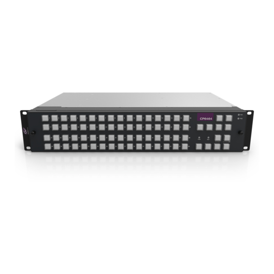
Introduction The Control Panel The Control Panel A thin 2RU control panel — the CP6464 — can mount directly on the front of the router as shown here: Dest. Lock Panel Lock Power LEDs Level (1–4) Unused (4) Selection Buttons (64) Fan LED Dest. -
Page 21: Definitions
CR6400 User’s Guide When a panel operator presses the destination selection button, the 64 selection buttons turn amber and permit the selection of one of 64 destinations. • Source Mode. The source mode button enables source selection using the array of selection buttons. When a panel operator presses the source selection button, the 64 selection buttons turn green and permit the selection of one of 64 sources. -
Page 22: Feature Summary
Introduction Feature Summary If a selection button is red when the panel is in destination mode, the destination is locked on the selected levels. The destination lock button will also be red in that case. The selection button is high-tally red when that destination is selected and low-tally red when some other destina- tion is selected. - Page 23 CR6400 User’s Guide Pressing the destination mode button makes the selection buttons (or I/O buttons) turn amber (high- or low-tally) In destination mode, the selection buttons select destinations. Other function buttons are reserved for future use. • Each button has a clear plastic cap that can be easily removed to accommodate customer- defined button legends.
- Page 24 Introduction Feature Summary...
-
Page 25: Installation
................. . . 19 Package Contents If you have ordered CR6400 routers (and products related to them) from Grass Valley, you should inspect the shipping container for damage. If you find any container damage, unpack and inspect the contents. -
Page 26: Design Considerations
Installation Design Considerations Design Considerations By the time you are ready to install your equipment and software, you (or someone in your orga- nization) will have already made most of the system design decisions. In fact, the design decisions will have been made before the equipment is ordered. The following is a review of the concepts. - Page 27 CR6400 User’s Guide router. Tabs at the ends of the control panel fit in slots in the face of the router, helping you align the panel to the router. As you install the panel, its buttons might flicker until you secure the panel in place. This is harmless.
-
Page 28: Creating A Router Network
Installation Creating a Router Network • Install the router in a rack so that the amount of air flow required for safe operation of the router is not compromised. • Mount the router in the rack so that a hazardous condition does not arise from uneven mechanical loading. -
Page 29: Testing
CR6400 User’s Guide Thus, subnet addresses for routers range from 101 to 104 and correspond to the router levels. The numbers on the rotary switch are in hexadecimal: 0–F. If the switch is at setting 0, the router will reset to its factory state, losing crosspoint values. You should avoid leaving the switch at setting 0. -
Page 30: Stand-Alone Network
Installation Testing Report any failures to Grass Valley customer service. Stand-Alone Network A stand-alone network comprises 1–4 CR6400 routers, a CP6464, and an Ethernet switch. 1 Ensure that each router has a unique rotary switch setting in the range 1–4. The switch posi- tion determines the router’s level. -
Page 31: Configuration
Configuration Chapter 4 provides configuration instructions for the CR6400 routers and the CP6464 panel. Topics Stand-Alone Routers ..............21 Stand-Alone Network . -
Page 32: Stand-Alone Network
Configuration Stand-Alone Network External Video Reference The reference connectors are a pair of 75 BNCs, loop-through, on the control card: Video Reference Connect your video reference input to either video reference connector on the rear of the router. Use the other video reference connector to feed the reference signal to another device. Terminate the reference signal (or chain of reference signals) using a 75 terminator. -
Page 33: Panel Configurations
CR6400 User’s Guide Levels and IP Addresses in Stand-Alone Networks, on page 18, for information on rotary switch settings and subnet addresses. Panel Configurations At this release, the CP6464 panels do not require configuration and it is not possible to configure them. -
Page 34: Panel Configurations
Configuration Panel Configurations... -
Page 35: Operation
Operation Chapter 5 provides operating instructions for the CR6400 routers and the CP6464 control panel. Topics Summary ................25 Stand-Alone Router . -
Page 36: Stand-Alone Router
Operation Stand-Alone Router 2 A source is set of N inputs on the routers in the network, where N is the number of routers. A source uses the same input on all N routers. For example, source 12 comprises input 12 on router 1, input 12 on router 2, input 12 on router 3, and input 12 on router 4. -
Page 37: Example
CR6400 User’s Guide 4 Press one of the selection buttons to select a source. The source’s button goes high-tally. The take is complete. Example You want to route input 4 (VTR2) to output 5 (MON1). The monitor is presently connected to input 3 (VTR1). -
Page 38: Panel Lock
Operation Stand-Alone Router Panel Lock Pressing ‘Panel Lock’ disables the control panel. Only the Panel Lock button remains enabled. Pressing it again re-enables the control panel. LOCK LOCK MODE MODE When the control panel is locked, the lock button is bright red and the state of the entire control panel is protected. -
Page 39: Stand-Alone Network
CR6400 User’s Guide To unlock a destination, press the selection button for the destination and then press Destina- tion Lock (again). The selection button for the destination reverts to amber and the ‘Destination Lock’ button goes low-tally amber. Stand-Alone Network A stand-alone network includes 1–4 CR6400 routers, one CP6464 panel, and an Ethernet switch. -
Page 40: Takes
Operation Stand-Alone Network The four level buttons on a control panel correspond to the four router levels, with level 1 on the left and level 4 on the right. (Destination Lock) (Panel Lock) Levels A level button is illuminated (in amber) if a router at that level is present in the network. The button is dark if not. -
Page 41: Panel Lock
CR6400 User’s Guide As previously stated, two of the function buttons are locks and four are level buttons. Two others are destination mode and source mode. Destination Lock Panel Lock LOCK LOCK Level selection buttons MODE MODE This illustration shows a system that has 3 levels (1–3), two of which are selected. Buttons for selected levels are high-tally. - Page 42 Operation Stand-Alone Network This sample shows destination 5 locked on levels 2 and 3, but not level 1: Locked LOCK LOCK Destination Destination Lock MODE MODE When you press ‘Destination Lock’ , immediately goes high-tally red and the selection button for the destination goes high tally red.
-
Page 43: Maintenance
If you experience difficulties with new routers, contact Grass Valley to request software and firmware upgrades. Update all your devices to the same firmware revision. If a router fails, you can perform certain simple diagnostics. Call Grass Valley if the problem cannot be solved easily. Trouble-Shooting If a CR6400 router or CP6464 malfunctions, first examine all input and output connections, all network connections, and all power connections. -
Page 44: Power Supply Led Does Not Illuminate
Trouble-Shooting Power Supply LED Does Not Illuminate If the device is otherwise functioning properly, the problem is a faulty LED. (Call Grass Valley for service.) If the router is not functioning at all, take the following steps. Determine whether the external power supply delivers power. (If you cannot do this, call Grass Valley.) If it does deliver power, try using the other PS connector. -
Page 45: Technical Details
Technical Details Chapter 7 provides electrical, video, audio, and mechanical specifications for the CR6400 family products. Topics Power Specifications ..............35 Reference Specifications . -
Page 46: Reference Specifications
Technical Details Reference Specifications The power supply is Grass Valley part PS0012-00: 35.0 175.0 [2.83] [1.38] 72.0 [2.83] Fig. 7-1: Power Supply Its power output has a 4-pin plug: Pins 1 and 4 are +48V; Pins 2 and 3 are ground, nominally 0V. The metal ring is ground also. - Page 47 CR6400 User’s Guide Compatibility between Video Formats and Reference Rates Comp Tri-Level Sync Video Format 525i / 59.94 625i / 50 720p / 23.98 720p / 24 ...
-
Page 48: Physical Specifications
Technical Details Physical Specifications Physical Specifications CR6400 Router Specifications Specification Detail Dimensions Height: 3.47” (88.1mm), fits EIA 2 RU (3.50” or 88.9mm), Width: 19.0” (482.6mm). Depth 10.18 ± 0.01” (258.6 mm), enclosure. 10.75” (273.1 mm) from front of rack to extended ground screw Weight 11.8 lb (5.35 kg) with no I/O cards, without control panel. -
Page 49: Environmental Specifications
The automation connector for the CR6400 routers has this pinout: TX– RX– n.c. The connector is RS-485, but can be used as RS-422. Customers who want to operate the router through an automation system or a control system may contact Grass Valley technical support for information. -
Page 50: Video Specifications
Technical Details Video Specifications Video Specifications CR6400 Digital Video Specifications Specification Detail 3Gig Auto re-clocking: 270 Mb/s, and 1.483, 1.485, 2.966, and 2.970 Gb/s, or auto bypass. Pass-through: 10 Mb/s to 3.0 Gb/s Input & output impedance: 75 . Input cable equalization >... -
Page 51: Audio Specifications
CR6400 User’s Guide Audio Specifications CR6400 Digital Audio (AES) Specifications Specification Detail Signal inputs Signal type: AES3id (2 “mono” channels per input). Sample rate: 32 kHz – 192 kHz. Input level: 1V p-p nominal into 75 . Input range: 200 mV p-p to 3 V p-p into 75 . Input return loss: <... - Page 52 Technical Details Drawings Fig. 7-2: Front View of the CR6400 Family Routers...
- Page 53 CR6400 User’s Guide Fig. 7-3: Rear Views of the CR6464-3Gig Router...
- Page 54 Technical Details Drawings Fig. 7-4: Rear Views of the CR6464-AES Router...
- Page 55 CR6400 User’s Guide Fig. 7-5: Front and Top Views of the CP6464 Control Panel...
-
Page 56: Defaults
Technical Details Defaults Defaults Default Router State The factory-default state is to be in stand-alone mode. The default routing state of a compact router is for input 1 to connect to output 1, input 2 to connect to output 2, and so on for all inputs and outputs. This is called a diagonal routing. (After you have made routing changes, the power-up state of the inputs and outputs is the state you last created.) ... -
Page 57: Misc. Topics
Misc. Topics Chapter 8 provides the following. Topics Power Cord Retention for the PS0012 Power Supply ........47 Power Cord Retention for the PS0012 Power Supply Use the supplied retention strap to keep the AC power cord firmly connected to the power supply. -
Page 58: Power Cord Retention
Misc. Topics Power Cord Retention for the PS0012 Power Supply 5 Continue the strap around toward the buckle loop and through the loop. Cinch the strap tightly. While keeping tension, place the 2 inch strap end (with Velcro loops) down on the fuzzy part to complete the process: 6 Examine the strap though its path around the cord and power supply. -
Page 59: Glossary
PCM and Dolby Digital 5.1, but is not tied to any particular sampling rate or any particular audio format. Grass Valley’s compact AES routers support AES3id and provide 75 BNC connectors. AES3id is specified for 75 coaxial cable up to 1000 meters. -
Page 60: Primary Level
(Super Wide Band). A term originated by Grass Valley’s NVISION business group that refers to the ability of a router to pass a wide range of digital bit rates and formats. Grass Valley’s SWB supports data rates from 10 Mbps to about 1.5 Gbps. The HD-SDI routers reclock at 143, 177, 270, 360, and 540MB/s and 1.483 and 1.485Gb/s. -
Page 61: Index
Index 0–9 3Gig video Cable, Ethernet ........17 routers . - Page 62 Digital audio specifications ......41 Grass Valley, technical support ..... . .39 Digital video specifications .
- Page 63 CR6400 User’s Guide Output connectors ........21 reclocking .
-
Page 64: Specifications
Index Remote panel modules ......50 Subnet address ........18 Restrictions . - Page 65 CR6400 User’s Guide router, 3Gig ........40, 50 router, HD .
- Page 66 Index...
-
Page 67: Contact Us
Contact Us Miranda Technical Support For technical assistance, please contact the Miranda Technical Support center nearest you: Americas Asia Office hours: 9:00 a.m. – 9:00 p.m. (EST) Office hours: 9:00 a.m. – 5:00 p.m. (GMT+8) Telephone: +1-800-224-7882 Telephone: +852-2539-6987 Fax: +1-514-335-1614 Fax: +852-2539-0804...
Need help?
Do you have a question about the CR6400 Series and is the answer not in the manual?
Questions and answers