Table of Contents
Advertisement
Quick Links
Advertisement
Table of Contents

Related Manuals for GRASS VALLEY Triton Plus


Summary of Contents for GRASS VALLEY Triton Plus
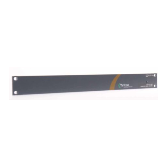
- Page 1 Triton Plus ANALOG STEREO AUDIO ROUTERS User Manual Revision 13 JANUARY 2009...
- Page 2 Affiliate with the N.V. KEMA in The Netherlands CERTIFICATE Certificate Number: 510040.001 The Quality System of: Grass Valley, Inc. 400 Providence Mine Road 15655 SW Greystone Ct. 10 Presidential Way Nevada City, CA 95945 Beaverton, OR 97006 Floor, Suite 300...
- Page 3 Triton Plus ANALOG STEREO AUDIO ROUTERS User Manual Revision 13 JANUARY 2009...
- Page 4 .pdf format can be downloaded. — Solutions to problems and troubleshooting efforts can be FAQ Database found by searching our Frequently Asked Questions (FAQ) database. — Download software updates, drivers, and patches. Software Downloads Triton Plus - Analog Stereo Audio - User Manual...
-
Page 5: Table Of Contents
Maximum Distance Between NCB Devices ......Connecting Signals to the Triton Plus Router...... - Page 6 Contents Triton Plus - Analog Stereo Audio - User Manual...
-
Page 7: Triton Plus Analog Stereo Audio Router
Plus fulfils the most demanding requirements from the professional broad- cast market. This User Manual presents the features listed below, installation and oper- ation procedures of the Analog Stereo Audio routers of the Triton Plus range. • Router range from 8x8 to 64x64 •... -
Page 8: Product Versions
Product Overview Product Versions The following versions of the Triton Plus Analog Stereo Audio Routers are available: • Analog Stereo Audio – 19 in., 1 RU, Depth - 5 cm (see Table • Analog Stereo Audio – 19 in., 2 RU, Depth - 5 cm (see Table •... - Page 9 Product Overview The following control panel versions are available for the Triton Plus series: • 19 in. 1 RU (Table • 19 in. 2 RU (Table • 19 in. 4 RU (Table Table 4. 19 in. 1 RU Control Panels...
-
Page 10: Connection Details
Connection Details Connection Details Available connectors at the back panel of the Triton Plus Routers are shown Figure Note Figure 1 shows a 1 RU Triton Plus router. However, the connectors are iden- tical to the 1 RU also on the 2 RU and 4 RU units. The only connectors that differ are the applicable signal connectors. -
Page 11: Power Supply Pinouts
Connection Details Power Supply Pinouts The DB9 power pinouts for Triton Plus routers and Control Panels are given in Table Table 7. Power Supply Pinouts Pin Number Description Not Connected Not Connected +15 VDC Not Connected Not Connected Not Connected... -
Page 12: Configuration
Configuration Configuration In order to get an overview of the parts that form the Triton Plus Analog Stereo Audio Router, this section highlights some of the main components. Router Level Switches 1-4 on the configuration switch set the router’s level for commu- nication with the Router Management System and other units in the NCB system. -
Page 13: Router Mode
Router Mode Router Mode on NxN Square Routers The Triton Plus A/V router allows switching in different modes. For a 1 RU Triton Plus router you can choose among the modes given in Table Table 9. 1 RU Triton Plus Modes... - Page 14 (8x8, 16x16, 32x32, or 64x64). Each table title identifies the number of router layers based on the router type: Table 13. 1 Router Layer Signal Input Signal Output Triton Plus - Analog Stereo Audio - User Manual...
- Page 15 Layer 1 Output Layer 2 Input Layer 2 Output Table 15. 2 Router Layers Based on an 16x16 Router Layer 1 Input Layer 1 Output Layer 2 Input Layer 2 Output Triton Plus - Analog Stereo Audio - User Manual...
- Page 16 Layer 1 Output Layer 2 Input Layer 2 Output Table 17. 2 Router Layers Based on an 64x64 Router Layer 1 Input Layer 1 Output Layer 2 Input Layer 2 Output Triton Plus - Analog Stereo Audio - User Manual...
- Page 17 Table 19. 3 Router Layers Based on an 32x32 Router Layer 1 Input Layer 1 Output Layer 2 Input Layer 2 Output Layer 3 Input Layer 3 Output Inputs/Outputs 31 and 32 are not used in this setup. Triton Plus - Analog Stereo Audio - User Manual...
- Page 18 Table 21. 4 Router Layers Based on an 8x8 Router Layer 1 Input Layer 1 Output Layer 2 Input Layer 2 Output Layer 3 Input Layer 3 Output Layer 4 Input Layer 4 Output Triton Plus - Analog Stereo Audio - User Manual...
- Page 19 Table 22. 4 Router Layers Based on an 16x16 Router Layer 1 Input Layer 1 Output Layer 2 Input Layer 2 Output Layer 3 Input Layer 3 Output Layer 4 Input Layer 4 Output Triton Plus - Analog Stereo Audio - User Manual...
- Page 20 Table 23. 4 Router Layers Based on an 32x32 Router Layer 1 Input Layer 1 Output Layer 2 Input Layer 2 Output Layer 3 Input Layer 3 Output Layer 4 Input Layer 4 Output Triton Plus - Analog Stereo Audio - User Manual...
- Page 21 Table 24. 4 Router Layers Based on an 64x64 Router Layer 1 Input Layer 1 Output Layer 2 Input Layer 2 Output Layer 3 Input Layer 3 Output Layer 4 Input Layer 4 Output Triton Plus - Analog Stereo Audio - User Manual...
-
Page 22: Power Alarm
SW 8 NxN square routers. The Triton Plus router provides two modes for pow- ering up the system. The power up options can be switched according to the following pattern given in Table Table 26. -
Page 23: Led Status Indication
Power is too low One Short Red Blink RXXXX XXXXX XXXXX XXXXX Power A failed Only active if power alarm DIP is set. Two Short Red Blinks XXXXX XXXXX RXRXX XXXXX Power B failed Triton Plus - Analog Stereo Audio - User Manual... -
Page 24: Router Communication
The communication parameters are configurable. Please refer to the pro- tocol documentation of the appropriate communication/control protocol. Example: The protocol parameters of the Triton Plus Compact routers are as follows: • Bit rate: 19200 bit/s • Data bits: 8 bits •... -
Page 25: Maximum Cable Length (Rs-232)
Up to 16 levels of routers, or combinations of routers, can be controlled. The NCB system and all RS-232 ports interchange the system status. This means that any control system, either from Grass Valley, or from a third party manufacturer, connected to any RS-232 port in the NCB loop, will have access to all communication data on the bus. -
Page 26: Termination Plug
The following connection example (Figure 2) shows connection of four Triton Plus devices with RJ-45 connectors and bus termination: Figure 2. Four Devices Connected Together Using RJ-45 Note Each device at the end of the chain has a termination plug, indicated with the letter T. -
Page 27: Control Bus Structure
Note The total number of Triton Plus devices in an NCB chain is limited to 50. Maximum Distance Between NCB Devices The standard MIDI definition allows a maximum cable length of 200-250 meters between two devices. -
Page 28: Connecting Signals To The Triton Plus Router
TPS-A0808 Audio Cabling (page 29) • Table A/V Toggle Button (page 31) • Table Pinout for OUTPUT CH.1-2 of TPS-A1602/A1602-CP (page 30) • Table Pinout for Unbalanced Audio Connection (page 30) Triton Plus - Analog Stereo Audio - User Manual... - Page 29 Table 33. TPS-A1616 Audio Cabling 9-16 9-16 9-16 9-16 INPUT CH.1 OUTPUT CH.1 INPUT CH.2 OUTPUT CH.2 Table 34. TPS-A0808 Audio Cabling CH.2 1-8 CH.2 1-8 INPUT OUTPUT CH.1 1-8 CH.1 1-8 Triton Plus - Analog Stereo Audio - User Manual...
- Page 30 Cold (-) Left CH.1 Left CH.2 Right CH.1 Right CH.2 If you want to use the Triton Plus audio router with unbalanced audio signals you connect these signals according to Table Table 37. Pinout for Unbalanced Audio Connection Triton Plus...
-
Page 31: Control Panel Operation
If neither audio nor video is present, it will be marked as disabled and the toggle state will not be used. Toggle status changes will be stored in flash and used when the panel is powered up later. Triton Plus - Analog Stereo Audio - User Manual... -
Page 32: Panel Enable
Input button. Then release the Panel Enable button. The panel will now be dis- abled. Press the Panel Enable button again to enable it. Triton Plus - Analog Stereo Audio - User Manual... -
Page 33: Specifications
Specifications Specifications Note All specifications are subject to change without notice. Table 39. Triton Plus Analog Stereo Audio Router Specifications Parameter Value Analog Audio Supported Formats Broadcast • N10, Pflichtenheft Nr. 3/5 1995 • Balanced analog audio 20Hz to 20kHz •... - Page 34 Specifications Table 39. Triton Plus Analog Stereo Audio Router Specifications Parameter Value Control Standard Features RS-232 for protocol conversion, to Triton Plus compact control protocol, or to Serial port 3rd party protocols Connector DB9, female NCB ports For integration with Triton Plus compact router configuration...
Need help?
Do you have a question about the Triton Plus and is the answer not in the manual?
Questions and answers