
Related Manuals for YASKAWA VS MINI J7 Series


Summary of Contents for YASKAWA VS MINI J7 Series
- Page 1 All manuals and user guides at all-guides.com VS mini J7 Series Instruction Manual COMPACT GENERAL-PURPOSE INVERTER (VOLTAGE VECTOR CONTROL)
- Page 2 Such modifications are denoted by a revised manual No. • To order a copy of this manual, contact your YASKAWA representative. • YASKAWA is not responsible for any modification of the product made by the user. Any modifications will void the warranty.
-
Page 3: Table Of Contents
All manuals and user guides at all-guides.com CONTENTS NOTES FOR SAFE OPERATION..... 5 1. RECEIVING ........12 •... - Page 4 All manuals and user guides at all-guides.com 7. PROGRAMMING FEATURES ....57 • Parameter Set-up and Initialization ....57 •...
-
Page 5: Notes For Safe Operation
All manuals and user guides at all-guides.com NOTES FOR SAFE OPERATION Read this instruction manual thoroughly before installation, operation, maintenance or inspection of the VS mini. In this manual, NOTES FOR SAFE OPERATION are classified as “WARNING” or “CAUTION”. WARNING Indicates a potentially hazardous situation which, if not avoided, could result in death or serious injury to personnel. - Page 6 All manuals and user guides at all-guides.com MOUNTING CAUTION (Ref. page) • Lift the inverter by the cooling fin. When moving the unit, never lift by the plastic case or the terminal covers. Failure to observe this caution may cause the unit to be dropped resulting in damage to the unit.
- Page 7 All manuals and user guides at all-guides.com WARNING (Ref. page) • For 400V class, make sure to ground the supply neutral. • Make sure to ground the ground terminal according to the local ground code. Failure to observe this warning can result in electric shock or fire.
- Page 8 All manuals and user guides at all-guides.com OPERATION WARNING (Ref. page) • Only turn ON the input power supply after replacing the digital operator or optional blank cover. Do not remove the digital operator or the covers while current is flowing. Failure to observe this warning can result in electric shock.
- Page 9 All manuals and user guides at all-guides.com CAUTION (Ref. page) • Never touch the heatsink or braking resistor, the temperature is very high. Failure to observe this caution can result in harmful burns to the body. • Since it is easy to change operation speed from low to high speed, verify the safe working range of the motor and machine before operation.
- Page 10 All manuals and user guides at all-guides.com WARNING (Ref. page) • Do not perform a voltage withstand test on any part of the VS mini J7. This electronic equipment uses semiconductors and it is vulnerable to high voltage..........99 •...
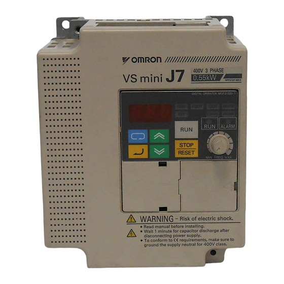
- Page 11 All manuals and user guides at all-guides.com WARNING LABEL A warning label is displayed on the front cover of the inverter, as shown below. Follow these instructions when handling the inverter. PLASTIC ENCLOSURE NAME- PLATE STATUS INDICATOR LAMP WARNING LABEL Warning Label •...
-
Page 12: Receiving
All manuals and user guides at all-guides.com 1. RECEIVING After unpacking the VS mini J7, check the following: • Verify that the part numbers match your purchase order or packing slip. • Check the unit for physical damage that may have occurred during shipping. If any part of VS mini J7 is missing or damaged, call for service immediately. -
Page 13: Identifying The Parts
All manuals and user guides at all-guides.com 2. IDENTIFYING THE PARTS... - Page 14 All manuals and user guides at all-guides.com Notes...
-
Page 15: Specifications
All manuals and user guides at all-guides.com 3. Specifications • Standard Specifications (200V Class) Voltage Class 200V single- / 3-phase 3-phase 20P1 20P2 20P4 20P7 21P5 22P2 23P7 Model CIMR-J7AU!!!! Single-phase B0P1 B0P2 B0P4 B0P7 B1P5 0.13 0.25 Max. Applicable Motor Output HP (kW)† (0.1) (0.2) (0.4) - Page 16 All manuals and user guides at all-guides.com Voltage Class 200V single- / 3-phase 3-phase 20P1 20P2 20P4 20P7 21P5 22P2 23P7 Model CIMR-J7AU!!!! Single-phase B0P1 B0P2 B0P4 B0P7 B1P5 Motor Overload Protection Electronic thermal overload relay Motor coasts to a stop at approx. 200% of inverter rated Instantaneous Overcurrent current Motor coasts to a stop after 1 minute at 150% of inverter rated...
- Page 17 All manuals and user guides at all-guides.com Voltage Class 200V single- / 3-phase 3-phase 20P1 20P2 20P4 20P7 21P5 22P2 23P7 Model CIMR-J7AU!!!! Single-phase B0P1 B0P2 B0P4 B0P7 B1P5 Status Indicator LED RUN and ALARM provided as standard LED’s Digital Operator Available to monitor frequency reference, output frequency, (JVOP-140) output current.
-
Page 18: Standard Specifications (400V Class)
All manuals and user guides at all-guides.com • Standard Specifications (400V Class) Voltage Class 400V 3-phase Model 3-phase 40P2 40P4 40P7 41P5 42P2 43P7 CIMR-J7A!!!! 0.25 Max. Applicable Motor Output HP (kW)* (0.2) (0.4) (0.75) (1.5) (2.2) (3.7) Inverter Capacity (kVA) Rated Output Current (A) Max. - Page 19 All manuals and user guides at all-guides.com Voltage Class 400V 3-phase Model 3-phase 40P2 40P4 40P7 41P5 42P2 43P7 CIMR-J7A!!!! Motor Overload Protection Electronic thermal overload relay Motor coasts to a stop at approx. 200% of inverter Instantaneous Over Current rated current Motor coasts to a stop after 1 minute at 150% of Overload...
- Page 20 All manuals and user guides at all-guides.com Voltage Class 400V 3-phase Model 3-phase 40P2 40P4 40P7 41P5 42P2 43P7 CIMR-J7A!!!! Status Indicator LED RUN and ALARM provided as standard LEDs Available to monitor frequency reference, output Digital Operator frequency, output current. 3 character, 7 segment LED display.
-
Page 21: Standard Wiring
All manuals and user guides at all-guides.com • Standard Wiring... - Page 22 All manuals and user guides at all-guides.com Terminal Description Type Terminal Name Function (Signal Level) Use main circuit power input (for single-phase inverter, R/L1, R/L1, S/L2). S/L2, AC power supply input Even thought T/L3 is available, do not use the terminal T/L3 for other purposes such as relay terminal.
-
Page 23: Dimensions
All manuals and user guides at all-guides.com • Dimensions... - Page 24 All manuals and user guides at all-guides.com Dimensions in inches (mm)/mass in lb (kg) Voltage Capacity Mass Fig. class HP (kW) 2.68 (68) 5.04 (128) 2.76 (70) 2.20 (56) 4.65 (118) 0.13 (0.1) 0.20 (5) 1.32 (0.6) 2.68 (68) 5.04 (128) 2.76 (70) 2.20 (56) 4.65 (118)
-
Page 25: Parameters List
All manuals and user guides at all-guides.com • Parameters List First Functions (Parameters n001 to n049) Register No. for Initial *User Ref. Name Description Trans- Setting Setting Page mission 0: Parameter n001 set / read and parameter n02 ~ n79 can be read. (FREF of the operator can be set.) 1: Functions (parameters n01 ~ n79) can be set / read. - Page 26 All manuals and user guides at all-guides.com Register No. for Initial *User Ref. Name Description Trans- Setting Setting Page mission Setting unit: 0.1Hz (less than 100Hz) / Maximum output 1Hz (100Hz or greater) 0109H 60.0Hz frequency Setting range: 50.0 ~ 400Hz Setting unit: 1V 230V (Note 1) 010AH...
- Page 27 All manuals and user guides at all-guides.com Register No. for Initial *User Ref. Name Description Trans- Setting Setting Page mission Setting unit: 0.1Hz (less than 100Hz) / 0118H Frequency reference 4 1Hz (100Hz or greater) 0.0Hz Setting range: 0.0 ~ 400Hz Setting unit: 0.1Hz (less than 100Hz) / 0119H Frequency reference 5...
- Page 28 All manuals and user guides at all-guides.com Register No. for Initial *User Ref. Name Description Trans- Setting Setting Page mission Parameter selection at Setting unit: 1min 0122H electronic thermal motor 8 min Setting range: 1 ~ 60min protection Cooling fan operation 0: Controls the cooling fan OFF / ON 0123H selection...
- Page 29 All manuals and user guides at all-guides.com Register No. for Initial *User Ref. Name Description Trans- Setting Setting Page mission 0: Fault 1: During run 2: Frequency agree 3: During zero speed 4: Frequency detection (detection level or greater) 5: Frequency detection (detection level or less) 6: During over torque detection (N.
- Page 30 All manuals and user guides at all-guides.com Register No. for Initial User Ref. Name Trans- Setting Setting Page mission 0: Output frequency 012CH Monitor item selection 1: Output current Setting unit: 0.01 012DH Monitor gain 1.00 Setting range: 0.01 ~ 2.00 Set value: 1 ~ 4 carrier frequency = set value ¥...
- Page 31 All manuals and user guides at all-guides.com Register No. for Initial User Ref. Name Trans- Setting Setting Page mission Setting unit: 1% Stall prevention (current Setting range: 30 ~ 200% 0139H 160% limit) during running (Note): If set at 200%, this function will not operate.
- Page 32 All manuals and user guides at all-guides.com Register No. for Initial User Ref. Name Trans- Setting Setting Page mission Setting unit: 1 0146H Slave address Setting range: 0 ~ 32 0: 2400 bps 1: 4800 bps 0147H Baud rate selection 2: 9600 bps 3: 19200 bps 0: Even parity...
- Page 33 All manuals and user guides at all-guides.com • KVA Dependant Parameter Default Settings 200V class 3-phase Name Unit Factory setting – Inverter capacity 0.1kW 0.2kW 0.4kW 0.75kW 1.5kW 2.2kW – 3.7kW Motor rated current – 14.1 Motor rated slip – Motor no-load –...
- Page 34 All manuals and user guides at all-guides.com Notes...
-
Page 35: Mounting
All manuals and user guides at all-guides.com 4. MOUNTING • Choosing a Location to Mount the Inverter Be sure the inverter is protected from the following conditions: • Extreme cold and heat. Use only within the ambient temperature range (for open chassis type): 14 to 122°F (-10 to +50°C) •... -
Page 36: Mounting Dimensions
All manuals and user guides at all-guides.com • Mounting Dimensions Clearances as shown below are required when mounting the VS mini. -
Page 37: Mounting/Removing Components
All manuals and user guides at all-guides.com • Mounting/Removing Components Removing and Mounting Digital Operator and Covers • Removing front cover Use a screwdriver to loosen the screw on the front cover surface to direction 1 to remove it. Then press the right and left sides to direction 2 and lift the front cover to direction 3. - Page 38 All manuals and user guides at all-guides.com Notes...
-
Page 39: Wiring
All manuals and user guides at all-guides.com 5. WIRING • Wiring Instructions (1) Always connect the power supply via a molded-case circuit breaker (MCCB) to the power input terminals R/L1, S/L2, and T/L3 (R/L1, S/L2 for single-phase). Never connect the power supply to U/T1, V/T2, W/T3,-,+1 or +2. The single-phase (200V class) inverter can be connected to a 200V 3-phase input. - Page 40 All manuals and user guides at all-guides.com 2. Main Circuit 200V Class 3-phase Input Series Wire Tightening Applicable Recommended Torque Model Terminal Symbol Screw size size lb • in Type (N • m) AWG mm R/L1,S/L2,T/L3,-,+1,+2,U/T1,V/T2,W/T3 7.1 to 8.88 18 to M3.5 0.75 to 2 CIMR-J7*U20P1...
- Page 41 All manuals and user guides at all-guides.com 400V Class 3-phase Input Series Wire Tightening Applicable Recommended Torque Model Terminal Symbol Screw size size lb • in Type (N • m) AWG mm R/L1,S/L2,T/L3,-,+1,+2,U/T1,V/T2,W/T3 7.1 to 8.88 14 to M3.5 2 to 5.5 CIMR-J7*U40P2 (0.8 to 1.0) R/L1,S/L2,T/L3,-,+1,+2,U/T1,V/T2,W/T3...
-
Page 42: Wiring The Main Circuit
All manuals and user guides at all-guides.com • Wiring the Main Circuit (Example of 3-phase, 200V class, 1.5kW inverters) • Main Circuit Input Power Supply When several VS mini J7 units are used Connect the power supply wiring to input side by side, ground each unit as shown in terminals L1 (R), L2(S) and L3(T) [L1(R), examples. -
Page 43: Recommended Peripheral Devices
MCCB type NF30 (MITSUBISHI) Magnetic contactor type HI HI-7E HI-7E HI-7E HI-7E HI-10-2E HI-10-2E HI-20E (YASKAWA CONTROL) • 200V single-Phase J7 * * J7 * * J7 * * J7 * * J7 * * VS mini J7 model B0P1 B0P2... - Page 44 All manuals and user guides at all-guides.com Surge suppressors Surge Suppressors Model Specifications Code No. Coils and relays DCR2- 250VAC Large size magnetic contactors 50A22E C002417 0.5µF 200Ω 200V Control relays MY-2, -3 (OMRON) 250VAC 230V 10A25C C002482 HH-22, -23 (FUJI) 0.1µF 100Ω...
-
Page 45: Wiring The Control Circuit
All manuals and user guides at all-guides.com • Wiring the Control Circuit Only basic insulation is provided for the control circuit terminals. Additional insulation may be necessary in the end product. • Control Circuit terminals Pass the cable through wiring hole and connect. Be sure to mount all the covers in the original position. -
Page 46: Wiring Inspection
All manuals and user guides at all-guides.com Open the front cover and verify that the strip length is 0.22 in. (5.5mm) • Wiring Inspection After completing wiring, check the following: • Wiring is properly connected. • Wire clippings or screws are not left inside the unit. •... -
Page 47: Operating The Inverter
All manuals and user guides at all-guides.com 6. OPERATING THE INVERTER • Test Run The inverter operates by setting the frequency (speed). There are three types of operation modes for the VS mini J7: 1. Run command from the digital operator (local potentiometer/digital setting). 2. - Page 48 All manuals and user guides at all-guides.com Operator 12-LED Status Operation Steps Display Display Indicator LED 1. Turn the local pot (volume control) fully counter clockwise 0.00 after turning the power ON. ALARM 2. Press DSPL 5 times to illuminate Lo/RE Lo/RE Select Lo (local mode) using ALARM...
-
Page 49: Operating The Digital Operator
All manuals and user guides at all-guides.com • Operating the Digital Operator All functions of the VS mini J7 are set by the digital operator. Below are descriptions of the display and keypad sections. Digital Operator... - Page 50 All manuals and user guides at all-guides.com Description of Status Indicator LED’s There are two LED’s on the middle right section of the face of the VS mini. The inverter status is indicated by various combinations of the LED’s (ON, BLINKING and OFF).
-
Page 51: Led Description
All manuals and user guides at all-guides.com • LED Description By pressing on the digital operator, each of the function LED’s can be selected. The following flowchart describes each function LED. 51 and 52... - Page 52 All manuals and user guides at all-guides.com Parameter Parameter No. (Refer to page 57) Return to Multi-Function monitor • Selecting monitor Press key. When is ON, data can be displayed by selecting monitor No. [Example] Monitoring Output Voltage Reference...
- Page 53 All manuals and user guides at all-guides.com • Monitoring Following items can be monitored by U-parameters Parameter Name Description Frequency reference Frequency reference can be monitored. U-01 (FREF) (Same as FREF) Output frequency Output frequency can be monitored. U-02 (FOUT) (Same as FOUT) Output current Output current can be monitored.
- Page 54 All manuals and user guides at all-guides.com Fault history display method Fault description is displayed when U09 is selected. (Example) !!!: Fault description (“---” is displayed if there is no fault.) (Refer to page 103 for details.) • Clearing fault history Set parameter n001 to 6 to clear fault history.
-
Page 55: Simple Data Setting
All manuals and user guides at all-guides.com • Simple Data Setting Volume setting (Refer to 5, OPERATING THE INVERTER) and digital setting are both available for simple accel/decel operation of the VS mini. Frequency reference by analog voltage is set with initial setting (n03 = 2). Following is an example in which the function LEDs are used to set frequency reference, acceleration time, deceleration time, and motor direction. - Page 56 All manuals and user guides at all-guides.com Notes...
-
Page 57: Programming Features
All manuals and user guides at all-guides.com 7. PROGRAMMING FEATURES Factory settings of the parameters are shown as in the tables. • Parameter Set-up and Initialization Parameter selection/initialization (n01) The following table describes the data which can be set or read when n01 is set. Unused parameters among n01 to n79 are not displayed. -
Page 58: Setting V/F Pattern
All manuals and user guides at all-guides.com • Selecting V/f pattern Adjusting torque according to application Adjust motor torque by using “V/f pattern” and “full-range automatic torque boost”. • V/f pattern setting Set V/f pattern by parameters n09 to n15 as described below. Set each pattern when using a special motor (high-speed motor, etc.) or when requiring special torque adjustment of machine. - Page 59 All manuals and user guides at all-guides.com • Typical setting of V/f pattern Set the V/f pattern according to the application as described below. For 400V class, the voltage values (n10, n13, and n15) should be doubled. When running at a frequency exceeding 50Hz/60Hz, change the maximum output frequency (n09).
- Page 60 All manuals and user guides at all-guides.com When operating with frequency larger than 60Hz/50Hz, change only maximum output frequency (n09). • Full-range automatic torque boost Motor torque requirement changes according to load conditions. Full range automatic torque boost adjusts voltage of V/f pattern according to the requirement. The VS mini J7 automatically adjusts the voltage during constant-speed operation as well as during acceleration.
-
Page 61: Switching Local/Remote Modes
All manuals and user guides at all-guides.com • Switching LOCAL/REMOTE Modes The following functions can be selected by switching the LOCAL or REMOTE mode. To select RUN/STOP commands or frequency reference, change the mode in advance depending on the following applications. •... -
Page 62: Selecting Run/Stop Commands
All manuals and user guides at all-guides.com • Selecting Run/Stop Commands Refer to page 63 to select either the LOCAL mode or REMOTE mode. Operation method (RUN / STOP commands, FWD / REV run commands) can be selected by the following method. •... -
Page 63: Selecting Frequency Reference
All manuals and user guides at all-guides.com • Selecting Frequency Reference Frequency reference can be selected by the following methods. • Setting by operator Select REMOTE or LOCAL mode in advance. For the method of selecting the mode, refer to page 62. LOCAL mode Parameter n07 determines where the frequency reference is input from when in the local mode. - Page 64 All manuals and user guides at all-guides.com *NOTE: SWB must be set to the “I” position when using terminal “FR” as a current reference input. Example of frequency reference by voltage signal n03: 2 (factory setting) SW8 is set to “V” position when using terminal “FR”...
-
Page 65: Setting Operation Condition
All manuals and user guides at all-guides.com • Setting Operation Conditions Reverse run prohibit (n06) The “Reverse run disabled” setting will not accept a reverse run command from the control circuit terminal or digital operator. This setting is used for applications where a reverse run command is undesirable. - Page 66 All manuals and user guides at all-guides.com Operating at Jog frequency reference By inputting a jog command and then a forward or (reverse) run command, operation is enabled at the jog frequency set in n29. When multi-step speed references 1, 2, 3 or 4 are input simultaneously with the jog command, the jog command has priority.
- Page 67 All manuals and user guides at all-guides.com • Adjusting speed setting signal The relationship between the analog input signal and internal (terminal “FR”) frequency reference can be set by parameters n41 and n42. FREQUENCY REFERENCE (a) Frequency reference gain (n41) The analog input voltage level for the maximum output frequency (n09) can be set in units of 1%.
- Page 68 All manuals and user guides at all-guides.com • To operate the inverter with frequency reference of 50% to 100% at 0 to 10V input Gain n41 = 100% Bias n42 = 50%...
- Page 69 All manuals and user guides at all-guides.com Adjusting frequency upper and lower limits Frequency reference upper (n30) and lower (n31) limits determines the range over which the inverter will operate. • Frequency reference upper limit (n30) Sets the upper limit of the frequency reference in units of 1%.
- Page 70 All manuals and user guides at all-guides.com At OFF: n16 (accel time 1) are used. n17 (decel time 1) At ON: n18 (accel time 2) are used. n19 (decel time 2) • Accel time Set the time needed for output frequency to reach 100% from 0%. •...
- Page 71 All manuals and user guides at all-guides.com Soft-start characteristics (n020) To prevent shock at machine start/stop, accel/decel can be performed in a S-curve pattern. Setting S-curve characteristic time S-curve characteristic not provided 0.2 second 0.5 second 1.0 second Note: The S-curve characteristics time from accel/decel rate 0 to a regular accel/decel rate determined by the set accel/decel time.
- Page 72 All manuals and user guides at all-guides.com The following time chart shows FWD/REV run switching at deceleration to a stop. Overtorque detection If an excessive load is applied to the machine, output current increase can be detected to output alarm signals to multi-function output terminals MA and MB. To output an overtorque detection signal, set output terminal function selection n40 to “overtorque detection”...
- Page 73 All manuals and user guides at all-guides.com • Overtorque detection function selection (n59) Setting Description Overtorque detection not provided Detected during speed agree, (alarm). Operation continues after detection. Detected during speed agree (fault). Operation stops during detection. Detected during running, operation continues after detection.
- Page 74 All manuals and user guides at all-guides.com Frequency detection (n58) Effective when the multi-function output terminal MA-MB-MC (parameter n40) is set to “frequency detection” (setting: 4 or 5). “Frequency detection” turns ON when output frequency is higher or lower than the frequency detection level (n58). •...
- Page 75 All manuals and user guides at all-guides.com Jump frequencies (n49 to n51) This function allows the prohibit or “jumping” of critical frequencies so that the motor can operate without resonance caused by machine characteristics. This function is also used for dead band control. Setting the value to 0.00Hz disables this function. Set prohibited frequency 1, 2 or as follows: n49 >...
- Page 76 All manuals and user guides at all-guides.com Starting into a rotating motor - Tripless Operation To start into a coasting motor without trip, use the speed search command or DC injection braking at start. • Speed search command Speed matches into a coasting motor upon starting without stopping the motor. This function enables smooth switching between motor commercial power supply operation and inverter operation.
- Page 77 All manuals and user guides at all-guides.com Accel/Decel Hold To hold acceleration or deceleration, use a multi-function input that is set to a value of “16: Accel/Decel Hold. The output frequency is kept constant when the accel/decel hold command is input during acceleration or deceleration. When the run command is removed during an accel/decel hold condition, accel/decel hold is internally released and operation ramps to stop.
- Page 78 All manuals and user guides at all-guides.com Using a frequency meter or ammeter (n44) Determines whether output frequency or output current is indicated on the analog output terminals, AM-AC, for monitoring. Setting Description Output frequency Output current Initial setting-analog voltage of approx. 10V is output when output frequency (output current) is 100%.
- Page 79 All manuals and user guides at all-guides.com Reducing motor noise leakage current (n46) Set inverter output transistor switching frequency (carrier frequency). Audible Noise RFI Noise and Setting Carrier Frequency (kHz) from Motor Current Leakage 12 fout (Hz) Higher Smaller 24 fout (Hz) 36 fout (Hz)
- Page 80 All manuals and user guides at all-guides.com Carrier Frequency Varies According to Inverter Capacity (kVA). Initial Setting Maximum Reduced Capacity Continuous Voltage Class Current (A) Carrier hp(kW) Output Current Setting Frequency 0.13 (0.1) 10kHz 0.25 (0.2) 10kHz – 0.5 (0.4) 10kHz 200V Single-phase...
- Page 81 All manuals and user guides at all-guides.com Operator stop key selection (n06) Selects whether the “STOP” key on the digital operator is effective when operating the inverter by an external source (input terminals or serial communications). Setting Description STOP key effective when running either from multi-function input terminals or communications. When STOP key is pressed, the inverter stops according to the setting of parameter n04.
-
Page 82: Selecting Stopping Method
All manuals and user guides at all-guides.com • Selecting Stopping Method Selecting stopping method (n04) Selects the stopping method when the run command is removed. Setting Description Deceleration to stop Coast to stop • Deceleration to stop (n04 =0) * When frequency reference is changed during running. Upon removal of the FWD (REV) run command, the motor decelerates at the decel rate determined by the time set to decel time 1 (n17) and DC injection braking is applied immediately before stop. - Page 83 All manuals and user guides at all-guides.com • Coast to stop (n04=1) * When frequency reference is changed during running. Upon removal of the FWD (REV) run command, the motor starts coasting. Applying DC injection braking • DC injection braking current (n52) Sets DC injection braking current level in units of 1%.
-
Page 84: Building Interface Circuits With External Devices
All manuals and user guides at all-guides.com • Building Interface Circuits with External Devices Using input signals Multi-function input terminal S2 to S5 functions can be changed when necessary by setting parameters n36 thru n39 respectively. Parameters n36 thru n39 cannot be set to the same value. - Page 85 All manuals and user guides at all-guides.com Terminal function at 3-wire sequence selection When 0 is set at the terminal S3 (n37), terminal S1 becomes run command, terminal S2 becomes stop command, and terminal S3 becomes FWD/REV run command. • LOCAL/REMOTE select (setting: 17) Select operation reference either by the digital operator or by the settings of operation method selection (n02) and frequency reference selection (n03).
- Page 86 All manuals and user guides at all-guides.com Time Chart at UP/DOWN Command Input Notes: (1) When UP/DOWN command is selected, the upper limit speed is set regardless of frequency reference. Upper limit speed = Maximum output frequency (n09) x Frequency reference upper limit (n030)/100 (2) Lower limit value is either minimum output frequency (n14) or Maximum output frequency (n09) x frequency reference lower limit (n31)/100% (whichever is greater).
- Page 87 All manuals and user guides at all-guides.com • Communication/multi-function input terminal selection input (setting: 18) (This function is effective when option card is installed) Operation can be changed from communication command, or from multi-function input terminal or digital operator command. Run command and frequency reference from communication options are effective when multi-function input terminal for this setting is “closed.”...
- Page 88 All manuals and user guides at all-guides.com Initial setting of multi-function output terminal Terminals Initial Setting MA, MB 1 (Inverter Run) + 2HZ OUTPUT FREQUENCY...
-
Page 89: Setting Frequency By Current Reference Input
All manuals and user guides at all-guides.com • Setting Frequency by Current Reference Input When setting frequency by inputting current reference (4-20mA or 0-20mA) from the control circuit terminal FR, switch the DIP switch SW8 on the control circuit board to “I” side. SW8 is accessed by removing the terminal cover. - Page 90 All manuals and user guides at all-guides.com Current reference selection After changing DIP switch (SW8) to the “I” side, PRESS on the digital PRGM operator, then set the following parameters. 4-20mA…n03 = 3 0-20mA…n03 = 4 Press the digital operator keys to run or stop the inverter.
- Page 91 All manuals and user guides at all-guides.com • Preventing Motor from Stalling (Current Limit) This function automatically limits the output current in response to load changes by adjusting the output frequency to prevent motor stalling. • Stall prevention (current limit) level during acceleration (n56) Sets the stall prevention (current limit) level during acceleration in units of 1% (Inverter rated current = 100%).
- Page 92 All manuals and user guides at all-guides.com • Stall prevention (current limit) level during running (n57) Sets the stall prevention (current limit) level during running in units of 1% (Inverter current = 100%). Factory setting: 160% A setting of 200% disables the stall prevention (current limit) during running. If the output current during speed agree exceeds the value set for n57 for longer than 100msec, deceleration starts.
-
Page 93: Decreasing Motor Speed Fluctuation
All manuals and user guides at all-guides.com • Decreasing Motor Speed Fluctuation Slip compensation As the load becomes larger, rotor speed is reduced as motor slip increases. The slip compensating function regulates the motor shaft speed as the load increases by increasing the output frequency. -
Page 94: Motor Protection
All manuals and user guides at all-guides.com • Motor Protection Motor overload detection Built-in electronic thermal overload protection is provided to protect against motor overheating. • Motor rated current (electronic thermal reference current, n32) Set to the rated current value shown on the motor nameplate. •... - Page 95 All manuals and user guides at all-guides.com • General-purpose motor and inverter motor Induction motors are classified as general-purpose motors (limited speed range) or inverter motors (wide speed range), based on their cooling capabilities. Therefore, the motor overload function operates differently between these two motor types. Example of 200V class motor Electronic Thermal Cooling Effect...
-
Page 96: Selecting Cooling Fan Operation
All manuals and user guides at all-guides.com • Selecting Cooling Fan Operation In order to increase fan life, the cooling fan can be set to operate when inverter is running or when power is supplied. n35 = 0 (factory setting) : Operates only when inverter is running. (Continues operation for 1 minute after inverter is stopped.) : Operates while power is ON. - Page 97 All manuals and user guides at all-guides.com • Communications specifications Interface RS-422, RS485 Synchronization Asynchronous (Start-stop synchronization) Communication Baud rate: Selected from 2400/4800/9600/19200 bps parameters Data length: 8 bits fixed Parity: Selected from even/odd/none Stop bits: 1 bit fixed Communication MEMOBUS (MODBUS) (RTU mode only) protocol Max.
- Page 98 All manuals and user guides at all-guides.com Notes...
-
Page 99: Maintenance And Inspection
All manuals and user guides at all-guides.com 8. Maintenance and Inspection • Periodical Inspection Periodically inspect the inverter as described in the following table to prevent accidents and to ensure high performance with high-reliability. Location to Check Check For Solution Terminal, unit mounting Connection hardware is properly Properly seat and tighten hardware. - Page 100 All manuals and user guides at all-guides.com Replacement of cooling fan • Inverter having W-dimension (width) 2.68 inches (68mm) 1. Removal (1) Press the right and left tabs of the fan cover inward (direction 1), and then pull them outward (direction 2) to remove the fan assembly from the inverter unit.
- Page 101 All manuals and user guides at all-guides.com • Inverter having W-dimension (width) 108mm (4.25 inches) 1. Removal (1) Remove the front cover and terminal cover, and then remove the cooling fan connector (CN10). (2) Press the right and left tabs of the fan cover inward (direction 1), and pull the fan cover downward (direction 2) to remove it from the inverter unit.
- Page 102 All manuals and user guides at all-guides.com NOTES...
-
Page 103: Fault Diagnosis And Corrective Actions
All manuals and user guides at all-guides.com 9. Fault Diagnosis and Corrective Actions This section describes the alarm and fault displays, explanations for fault conditions and corrective actions to be taken if the VS mini J7 malfunctions. < Corrective Actions for models without digital operator > 1. - Page 104 All manuals and user guides at all-guides.com < Corrective Actions of Models with Digital Operator > : ON : Blinking : OFF Alarm Display and Contents Alarm Display Inverter Causes and Explanation Digital ALARM Status Corrective Actions (Green) (Red) Operator UV (Main circuit low voltage) Check the following: Main circuit DC voltage drops...
- Page 105 All manuals and user guides at all-guides.com Alarm Display Inverter Causes and Explanation Digital ALARM Status Corrective Actions (Green) (Red) Operator OP! (parameters setting Check the setting error when the parameters values. setting is performed through the MEMOBUS communications) OP1: Two or more values are set for multi-function input selection.
- Page 106 All manuals and user guides at all-guides.com Alarm Display Inverter Causes and Explanation Digital ALARM Status Corrective Actions (Green) (Red) Operator BB (External base block) Check the external Baseblock command at multi- circuit (sequence). function terminal is active. The inverter output is shut OFF (motor coasting).
- Page 107 All manuals and user guides at all-guides.com Alarm Display Inverter Causes and Explanation Digital ALARM Status Corrective Actions (Green) (Red) Operator OC (Over current) • Short circuit or Inverter output current grounding at inverter momentarily exceeds approx. output side. 200% of rated current. •...
- Page 108 All manuals and user guides at all-guides.com Alarm Display Inverter Causes and Explanation Digital ALARM Status Corrective Actions (Green) (Red) Operator OH (Cooling fin overheat) • Excessive load Temperature rise because of • Improper V/f pattern inverter overload operation or setting intake air temperature rise.
- Page 109 All manuals and user guides at all-guides.com Alarm Display Inverter Causes and Explanation Digital ALARM Status Corrective Actions (Green) (Red) Operator Check the external (External fault) circuit (sequence). Inverter receives an external fault input from control circuit terminal. EF0: External fault reference through MEMOBUS communications EF2: External fault input...
- Page 110 All manuals and user guides at all-guides.com Alarm Display Inverter Causes and Explanation Digital ALARM Status Corrective Actions (Green) (Red) Operator CPF-05 Cycle power. AD converter fault is detected If the fault remains, replace the inverter. CPF-06 Remove power to the •...
-
Page 111: Appendix
All manuals and user guides at all-guides.com Appendix - CE Conformance CE Conformance - Low Voltage Directive (LVD) Compliance • These circuits are hazardous and are separated from accessibility by protective separation. ‚ These circuits are not separated from hazardous circuits by protective separation, but only with basic insulation. - Page 112 (max. 20m) must be used and the screen of the motor cable is connected to ground at both ends by a short connection, using as large an area as practical. For a more detailed explanation, please refer to Making YASKAWA Inverter Products Conform with EMC Directive (G-TI#99012-V7).
- Page 113 All manuals and user guides at all-guides.com Recommended Line Filters for VS mini J7 made by Rasmi Electronic Ltd (200 V three phase) Current Weight Dimension VS mini J7 Model (kg) W×D×H CIMR-J7AU20P1 CIMR-J7AU20P2 RS 2010-J7 82 x 50 x 194 CIMR-J7AU20P4 CIMR-J7AU20P7 CIMR-J7AU21P5...
- Page 114 All manuals and user guides at all-guides.com Installation of Line Filter and Inverter VS mini J7 (CIMR-J7 ¨¨20P1 to 23 P7) L1 L2 L3 P E Shield Cable Control Panel Rasmi Filter R S T Ground VS mini Bonds (remove paint) U V W Shield...
- Page 115 All manuals and user guides at all-guides.com Installation of Line Filter and Inverter VS mini J7 (CIMR-J7 ¨¨B0P1 to B1P5) Shield Cable Control Panel Metal Rasmi Mounting Plate Filter Ground Bonds VS mini (remove paint) U V W Shield Cable Ground Bonds (remove any paint) Max.20m...
- Page 116 This also applies for equipment with CE approvals. Compliance with the EMC legislation limits is the responsibility of the machine or system manufacturer. RCCBs For information on the use of RCCBs with inverters please contact your supplier or Yaskawa representative. Operation In some systems it may be necessary to install additional monitoring and protective facilities to comply with the applicable safety and accident prevention regulations.
- Page 117 Responsibility As a component manufacturer we are responsible for the provision of installation instructions. These can be found in the installation guidelines publication G-TI#99012-V7 (a Yaskawa publication free upon request). Our products have been tested by authorized bodies pursuant to the requirements of the standard listed below.
- Page 118 All manuals and user guides at all-guides.com YASKAWA ELECTRIC AMERICA, INC. Chicago-Corporate Headquarters 2121 Norman Drive South, Waukegan, IL 60085, U.S.A. Phone: (847) 887-7000 Fax: (847) 887-7310 Internet: http://www.yaskawa.com MOTOMAN INC. 805 Liberty Lane, West Carrollton, OH 45449, U.S.A. Phone: (937) 847-6200 Fax: (937) 847-6277...
Need help?
Do you have a question about the VS MINI J7 Series and is the answer not in the manual?
Questions and answers