
Related Manuals for Texas Instruments CDCE906


Summary of Contents for Texas Instruments CDCE906
- Page 1 CDCE906/CDCE706 Performance Evaluation Module User's Guide August 2007 High Performance Analog/CDC SCAU016B...
- Page 2 SCAU016B – August 2006 – Revised August 2007 Submit Documentation Feedback...
-
Page 3: Table Of Contents
......................... Quick Start ......................EVM Hardware ................Board View and Connector Location ..................Hardware Configuration ......................TI Pro-Clock™ ................CDCE906-706 SMBus Interface ..............CDCE906-706 Programming Assistant ......................Tutorial .................... Software Installation ................................................Parts List ..................Board Layout and Schematic ....................... - Page 4 List of Figures ................. CDCE906/CDCE706 Functional Block Diagram ..................CDCE906/CDCE706 Default Setup ........................Board View ..................CDCE906-706 SMBus Interface ....................Programming Assistant ......................Top Silkscreen ........................Top Side ........................Ground ........................Power ......................Bottom Silkscreen ......................Schematic - Page 1 ......................
-
Page 5: Introduction
= 167 MHz, commercial temperature range) The performance of the CDCE906 and the CDCE706 is equal, but the CDCE906 has a limited output frequency and temperature range for operating. Because of this, the CDCE706 is used on this board for evaluation purposes. -
Page 6: Cdce906/Cdce706 Functional Block Diagram
(outputs disable to low, outputs 3-state, power down, PLL bypass, etc). The CDCE906/CDCE706 has three power supply pins, VCC, VCCOUT1, and VCCOUT2. VCC is the power supply for the device. It operates from a single 3.3-V supply voltage. VCCOUT1 and VCCOUT2 are the power supply pins for the outputs. - Page 7 Introduction Related Documentation From Texas Instruments • CDCE906, Programmable 3-PLL Clock Synthesizer/Multiplier/Divider data sheet (SCAS814) • CDCE706, Programmable 3-PLL Clock Synthesizer/Multiplier/Divider data sheet (SCAS815) SCAU016B – August 2006 – Revised August 2007 CDCE906/CDCE706 Performance Evaluation Module Submit Documentation Feedback...
-
Page 8: Quick Start
PLLs and all outputs are active and in non-inverting mode. S0, S1, and SSC comply according the default setting described in byte 10 and byte 25 (see the data sheet) respectively. Figure 2 to view the CDCE906/CDCE706 default setup. = 216 MHz VCO1... -
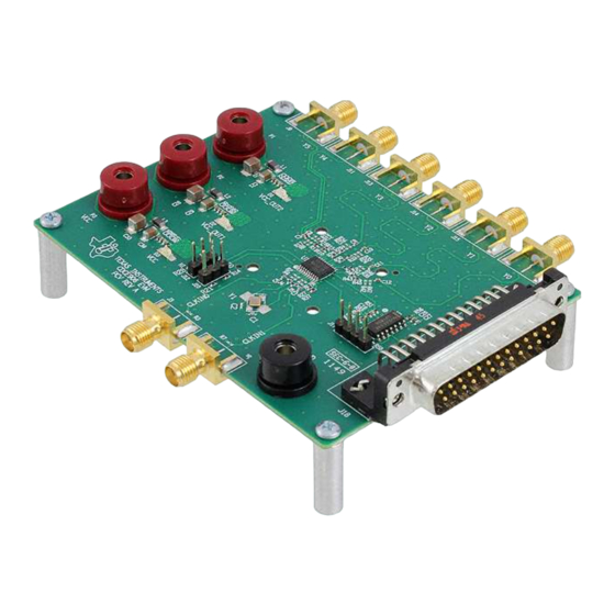
Page 9: Evm Hardware
Default setting: J12 and J10 are not used. Note: S0 and S1 are logic high due to their internal pull-up resistors if J10 and J12 are not used. SCAU016B – August 2006 – Revised August 2007 CDCE906/CDCE706 Performance Evaluation Module Submit Documentation Feedback... - Page 10 EVM with high impedance input, that is connected to the CDCE906/E706 performance EVM. However, the output load is too low if Y0–Y5 is connected directly to a 50 Ω parallel termination. This results in a violation of the ac-parameters mentioned in the data sheet.
-
Page 11: Ti Pro-Clock
TI Pro-Clock™ TI Pro-Clock™ TI Pro-Clock™ is the evaluation software for the CDCE906 and the CDCE706. The software contains the CDCE906-706 SMBus Interface and the CDCE906-706 Programming Assistant. In the future, the software will be expanded for new devices. The software runs under Windows 2000, XP, and XP*64. A quick installation is required prior to use. -
Page 12: Cdce906-706 Programming Assistant
By selecting auto write in the upper right corner, the CDCE906/CDCE706 SMBus control register gets an update after each change in the setup of the CDCE906-706 SMBus Interface. If graph ser data is selected, the bit pattern of SCLK and SDATA is shown on a screen. -
Page 13: Programming Assistant
The Programming Assistant starts with its own default setup. The default setup of the Programming Assistant is different to the default setup of the CDCE906/CDCE706. This is why, the Programming Assistant has a simple startup setup, which makes it easy to create a new user-defined setup. From this default setup, different parameters can be edited to create a user setup. -
Page 14: Tutorial
This section contains a step-by-step tutorial for creating a user-defined setup and programming the CDCE906/E706. The 27-MHz crystal of the EVM is used for reference. A 64-MHz CPU clock, different audio sample clocks for 24-kHz audio rate, a 27-MHz clock for an MPEG/AC-3 Audio Dec, and an additional 60-MHz clock is provided. -
Page 15: Software Installation
1. Download TI Pro-Clock™ from www.ti.com. 2. Run program setup.exe. 3. Reboot your computer. 4. Run the Software from Start → Programs → Texas Instruments → TI Pro Clock. SCAU016B – August 2006 – Revised August 2007 CDCE906/CDCE706 Performance Evaluation Module... -
Page 16: Faq
The output impedance is probably too small. Enlarge the output impedance as written in section 3.2.5. The CDCE906/CDCE706 register cannot be programmed. What is wrong? Check if the parallel port is connected to your PC and your EVM. Check if all voltages are applied. - Page 17 Panasonic ERJ-2RKF1000X R52, R54 100 kΩ Panasonic ERJ-2RKF1003X CDCE706 CDCE706 SN74LV125 Texas Instruments SN74LV125AD 27 MHz Crystal Epson Toyocom TSX 3225 Stand Off MP32 Screw SCAU016B – August 2006 – Revised August 2007 CDCE906/CDCE706 Performance Evaluation Module Submit Documentation Feedback...
-
Page 18: Board Layout And Schematic
Board Layout and Schematic Board Layout and Schematic The following figures show the board layout and schematic. Figure 6. Top Silkscreen CDCE906/CDCE706 Performance Evaluation Module SCAU016B – August 2006 – Revised August 2007 Submit Documentation Feedback... -
Page 19: Top Side
Board Layout and Schematic Figure 7. Top Side SCAU016B – August 2006 – Revised August 2007 CDCE906/CDCE706 Performance Evaluation Module Submit Documentation Feedback... - Page 20 Board Layout and Schematic Figure 8. Ground CDCE906/CDCE706 Performance Evaluation Module SCAU016B – August 2006 – Revised August 2007 Submit Documentation Feedback...
- Page 21 Board Layout and Schematic Figure 9. Power SCAU016B – August 2006 – Revised August 2007 CDCE906/CDCE706 Performance Evaluation Module Submit Documentation Feedback...
-
Page 22: Bottom Silkscreen
Board Layout and Schematic Figure 10. Bottom Silkscreen CDCE906/CDCE706 Performance Evaluation Module SCAU016B – August 2006 – Revised August 2007 Submit Documentation Feedback... - Page 23 Board Layout and Schematic Figure 11. Schematic - Page 1 SCAU016B – August 2006 – Revised August 2007 CDCE906/CDCE706 Performance Evaluation Module Submit Documentation Feedback...
- Page 24 Board Layout and Schematic Figure 12. Schematic - Page 2 CDCE906/CDCE706 Performance Evaluation Module SCAU016B – August 2006 – Revised August 2007 Submit Documentation Feedback...
- Page 25 This evaluation module (EVM) being provided by Texas Instruments (TI) is intended for use for ENGINEERING DEVELOPMENT OR EVALUATION PURPOSES ONLY and is not considered by Texas Instruments to be fit for commercial use. As such, this EVM may not be complete in terms of design and/or manufacturing related protective considerations including product safety measures typically found in the end-product incorporating the module.
- Page 26 EVM schematic located in the EVM User's Guide. When placing measurement probes near these devices during operation, please be aware that these devices may be very warm to the touch. Mailing Address: Texas Instruments, Post Office Box 655303, Dallas, Texas 75265 Copyright 2006-2007, Texas Instruments Incorporated...
-
Page 27: Important Notices
TI as compliant with ISO/TS 16949 requirements. Buyers acknowledge and agree that, if they use any non-designated products in automotive applications, TI will not be responsible for any failure to meet such requirements. Following are URLs where you can obtain information on other Texas Instruments products and application solutions: Products... - Page 28 Mouser Electronics Authorized Distributor Click to View Pricing, Inventory, Delivery & Lifecycle Information: Texas Instruments CDCE906-706PERFEVM...
Need help?
Do you have a question about the CDCE906 and is the answer not in the manual?
Questions and answers