Texas Instruments CC3200 User Manual
Simplelink wi-fi and iot solution with mcu launchpad hardware
Hide thumbs
Also See for CC3200:
- Technical reference manual (572 pages) ,
- Programmer's manual (73 pages) ,
- User manual (22 pages)

Subscribe to Our Youtube Channel
Related Manuals for Texas Instruments CC3200


Summary of Contents for Texas Instruments CC3200
- Page 1 CC3200 SimpleLink™ Wi-Fi and IoT Solution ® with MCU LaunchPad Hardware User's Guide Literature Number: SWRU372B June 2014 – Revised January 2015...
-
Page 2: Table Of Contents
The CC3200 Code Examples .................... CC3200 Application Notes ......................The Community ......................Known Limitations ....................Hardware Limitations .......................... Revision History .......................... Revision History Table of Contents SWRU372B – June 2014 – Revised January 2015 Submit Documentation Feedback Copyright © 2014–2015, Texas Instruments Incorporated... - Page 3 ......................Jumper Settings ....................... UART Signals ........................SOP Lines ....................Miscellaneous Settings ........................ Push Buttons ......................... LEDs ......................... Change Log SWRU372B – June 2014 – Revised January 2015 List of Figures Submit Documentation Feedback Copyright © 2014–2015, Texas Instruments Incorporated...
-
Page 4: Introduction
Introduction CC3200 LaunchPad The high performance CC3200 is the industry's first single-chip Microcontroller (MCU) with built-in Wi-Fi connectivity for the LaunchPad™ ecosystem. Created for the Internet of Things (IoT), the SimpleLink Wi- Fi CC3200 device is a wireless MCU that integrates a high-performance ARM... -
Page 5: What's Included
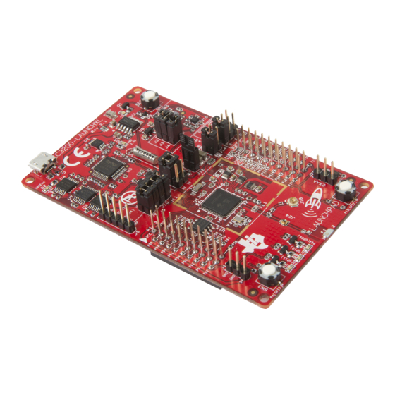
Micro USB cable • Quick start guide FCC/IC Regulatory Compliance The CC3200 SimpleLink Wi-Fi and IoT solution with MCU LaunchPad hardware is FCC Part 15 and IC ICES-003 Class A compliant. Hardware Description Figure 1. CC3200 LaunchPad EVM Overview SWRU372B – June 2014 – Revised January 2015 CC3200 SimpleLink™... -
Page 6: Block Diagram
Block Diagram Figure 2. CC3200 Block Diagram Hardware Features • CC3200, SimpleLink Wi-Fi, internet-on-a-chip solution with integrated MCU40-pin LaunchPad standard that leverages the BoosterPack ecosystem • FTDI-based JTAG emulation with serial port for Flash programming • Supports both 4-wire JTAG and 2-wire SWD •... -
Page 7: Connecting A Boosterpack
“key” to prevent the misalignment of the pins or reverse connection. Ensure that Vcc and 5V pins, are aligned with the BoosterPack header pins. On the CC3200 LaunchPad, a small white triangle symbol is provided near Pin-1 (see Figure 3) to orient all BoosterPacks. -
Page 8: I2C Connections
Open: Isolate the on-board emulator from the CC3200. J11(TDO) For the SWD mode, only TCK and TMS need to be shorted to the CC3200. When a battery is used, be sure to disconnect all the JTAG headers to prevent any reverse leakage current. -
Page 9: Default I2C Addresses
The board can be powered by using the on-board micro USB connector. An on-board LDO provides 3.3 V for the CC3200 and the rest of the board to operate. This supply can be isolated from the LDO using the jumpers on the board. -
Page 10: Uart Signals
Short 2-3: Route the signals to the FTDI for Flash programming. CC3200 SimpleLink™ Wi-Fi ® and IoT Solution with MCU LaunchPad SWRU372B – June 2014 – Revised January 2015 Hardware Submit Documentation Feedback Copyright © 2014–2015, Texas Instruments Incorporated... -
Page 11: Sop Jumpers
Sense on Power The CC3200 can be set to operate in three different modes based on the state of the Sense on Power (SOP) lines. These are pins 21, 34, 35 on the CC3200 device. The state of the device is described in Table Table 6. -
Page 12: Miscellaneous Settings
To observe the Network Processor (NWP), MAC Logs. SOP2 Isolation Isolate SOP2 (GPIO_25) from the 20 pin connector CC3200 SimpleLink™ Wi-Fi ® and IoT Solution with MCU LaunchPad SWRU372B – June 2014 – Revised January 2015 Hardware Submit Documentation Feedback Copyright © 2014–2015, Texas Instruments Incorporated... -
Page 13: Push Buttons
Reference Usage Comments RESET This is used to RESET the CC3200 device. This signal is also output on the 20-pin connector to RESET any external BoosterPack which may be stacked. GPIO_22 When pushed, the GPIO_22 will be pulled to VCC. - Page 14 GPIO_10 and GPIO_11 are used as I2C also. So whenever the pull-ups are enabled, the LEDs would glow. CC3200 SimpleLink™ Wi-Fi ® and IoT Solution with MCU LaunchPad SWRU372B – June 2014 – Revised January 2015 Hardware Submit Documentation Feedback Copyright © 2014–2015, Texas Instruments Incorporated...
-
Page 15: Power
The LaunchPad is designed such that it can be powered by the USB connection or by external 2xAA/2xAAA batteries. SWRU372B – June 2014 – Revised January 2015 CC3200 SimpleLink™ Wi-Fi ® and IoT Solution with MCU LaunchPad Hardware Submit Documentation Feedback Copyright © 2014–2015, Texas Instruments Incorporated... -
Page 16: Powering From Usb
Figure J12 (shorted) J13 (shorted) Figure 9. Powering From USB CC3200 SimpleLink™ Wi-Fi ® and IoT Solution with MCU LaunchPad SWRU372B – June 2014 – Revised January 2015 Hardware Submit Documentation Feedback Copyright © 2014–2015, Texas Instruments Incorporated... -
Page 17: Measure Cc3200 Current Draw
Measure CC3200 Current Draw To measure the current draw of the CC3200, use the 3V3 jumper on the jumper isolation block. (J12). The current measured in this mode includes only the CC3200 current and no external blocks. However, if a GPIO of the CC3200 is driving a high current load like LED, then that is also included in this measurement. -
Page 18: Measuring Low Power
Figure 11. Measuring Low Power 1. Remove the 3V3 jumper (J12); attach an ammeter across this jumper. 2. Make sure that the CC3200 is not driving any high current loads directly like an LED as this can cause large current drawn. -
Page 19: Measuring Active Power
4. An ammeter can also be used for this measurement, but the results may be erroneous due to the switching nature of the current. SWRU372B – June 2014 – Revised January 2015 CC3200 SimpleLink™ Wi-Fi ® and IoT Solution with MCU LaunchPad Hardware Submit Documentation Feedback Copyright © 2014–2015, Texas Instruments Incorporated... -
Page 20: Rf Connections
Resistor mounted towards U.FL Murata connector Figure 14. Board Set for Conducted Testing CC3200 SimpleLink™ Wi-Fi ® and IoT Solution with MCU LaunchPad SWRU372B – June 2014 – Revised January 2015 Hardware Submit Documentation Feedback Copyright © 2014–2015, Texas Instruments Incorporated... -
Page 21: Design Files
All design files including firmware patches, software example projects, and documentation are made available from the SimpleLink Wi-Fi Platform page. The Software Development Kit (SDK) to use with the CC3200 LaunchPad can be obtained from http://www.ti.com/tool/cc3200sdk. SWRU372B – June 2014 – Revised January 2015 CC3200 SimpleLink™ Wi-Fi ®... -
Page 22: Software Examples
For more details on where to download the latest IDE, see Section 4.3. The CC3200 Programmer's guide (SWRU369) has detailed information on software environment setup, and examples. Please refer to this document for further details on the software sample examples. 3.1.1 CCS 6.0 or higher is required. -
Page 23: The Community
Floating S-Flash Lines (Rev 3.2 and Earlier) The SPI lines routed from the CC3200 to the on-board serial flash are not pulled up or down using resistors on the board. When the device enters Hibernate state, these pins can be floating and high currents can be drawn by the serial flash. -
Page 24: Revision History
5 of this chapter. 3.1.2 For EVMs annotated as FCC – FEDERAL COMMUNICATIONS COMMISSION Part 15 Compliant: CAUTION Revision History SWRU372B – June 2014 – Revised January 2015 Submit Documentation Feedback Copyright © 2014–2015, Texas Instruments Incorporated... - Page 25 Antenna types not included in this list, having a gain greater than the maximum gain indicated for that type, are strictly prohibited for use with this device. Concernant les EVMs avec antennes détachables SWRU372B – June 2014 – Revised January 2015 Revision History Submit Documentation Feedback Copyright © 2014–2015, Texas Instruments Incorporated...
- Page 26 EVM, including without limitation any warning or restriction notices. The notices contain important safety information related to, for example, temperatures and voltages. 4.3 Safety-Related Warnings and Restrictions: Revision History SWRU372B – June 2014 – Revised January 2015 Submit Documentation Feedback Copyright © 2014–2015, Texas Instruments Incorporated...
- Page 27 CONTRACT OR ANY OTHER LEGAL THEORY, AND EVEN IF THE EVM FAILS TO PERFORM AS DESCRIBED OR EXPECTED. Limitations on Damages and Liability: SWRU372B – June 2014 – Revised January 2015 Revision History Submit Documentation Feedback Copyright © 2014–2015, Texas Instruments Incorporated...
- Page 28 County, Texas. Notwithstanding the foregoing, any judgment may be enforced in any United States or foreign court, and TI may seek injunctive relief in any United States or foreign court. Revision History SWRU372B – June 2014 – Revised January 2015 Submit Documentation Feedback Copyright © 2014–2015, Texas Instruments Incorporated...
- Page 29 IMPORTANT NOTICE Texas Instruments Incorporated and its subsidiaries (TI) reserve the right to make corrections, enhancements, improvements and other changes to its semiconductor products and services per JESD46, latest issue, and to discontinue any product or service per JESD48, latest issue.
Need help?
Do you have a question about the CC3200 and is the answer not in the manual?
Questions and answers