Table of Contents
Advertisement
Quick Links
UM0488
User manual
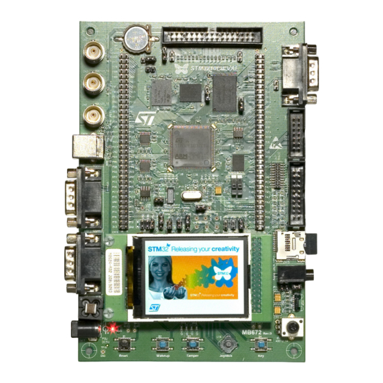
Evaluation board with STM32F103Zx MCU
Introduction
The STM3210E-EVAL Evaluation board is a complete development platform for
®
®
STMicroelectronics Arm
Cortex
-M3 core-based STM32F103ZGT6 microcontroller with
2
2
full-speed USB 2.0, CAN 2.0 A/B compliant interface, two I
S channels, two I
C channels,
five USART channels with smartcard support, three SPI channels, two DAC channels,
FSMC interface, SDIO, internal 96-Kbyte SRAM and 1-Mbyte flash memory, and JTAG and
SWD debug support.
The STM3210E-EVAL products delivered with the MB672 board versions D-03 or older are
based on the STM32F103ZET6 instead of the STM32F103ZGT6 and include 64-Kbyte
internal SRAM and 512-Kbyte flash memory. The board number and version are on a label
on the bottom side of the board.
The full range of hardware features on the board helps the user to evaluate all peripherals
(USB, motor control, CAN, microSD™ card, smartcard, USART, NOR and NAND flash
memories, SRAM) and develop his applications. Extension headers make it easy to connect
a daughterboard or wire-wrap board for his specific application.
Figure 1. STM3210E-EVAL Evaluation board
Picture is not contractual.
April 2022
UM0488 Rev 7
1/45
www.st.com
1
Advertisement
Table of Contents

Related Manuals for ST STM3210E-EVAL


Summary of Contents for ST STM3210E-EVAL
-
Page 1: Figure 1. Stm3210E-Eval Evaluation Board
FSMC interface, SDIO, internal 96-Kbyte SRAM and 1-Mbyte flash memory, and JTAG and SWD debug support. The STM3210E-EVAL products delivered with the MB672 board versions D-03 or older are based on the STM32F103ZET6 instead of the STM32F103ZGT6 and include 64-Kbyte internal SRAM and 512-Kbyte flash memory. -
Page 2: Table Of Contents
Contents UM0488 Contents Features ........... 7 Ordering information . - Page 3 Product marking ..........39 STM3210E-EVAL product history ....... 39 8.2.1...
- Page 4 Contents UM0488 8.5.3 Board MB672 revision D-05 limitations ......40 8.5.4 Board MB672 revision D-06 limitations ......40 8.5.5 Board MB895 revision C-03 limitations .
- Page 5 STM3210E-EVAL I/O assignment ........
- Page 6 STM3210E-EVAL Evaluation board layout ........
-
Page 7: Features
UM0488 Features Features ®(a) ® • STM32F103ZGT6 Arm Cortex -M3 core-based microcontroller with 1 Mbyte of flash memory and 96 Kbytes of SRAM, in a 144-pin TQFP package • 240 x 320.pixel TFT color LCD • S audio DAC, with stereo output •... -
Page 8: Ordering Information
Ordering information UM0488 Ordering information To order the STM3210E-EVAL Evaluation board, refer to Table 1. Additional information is available from the datasheet and reference manual of the target microcontroller. Table 1. Ordering information Order code Board references Target STM32 STM32F103ZET6... -
Page 9: Development Environment
UM0488 Development environment Development environment System requirements ® ® (a) ® (b) • Multi.OS support: Windows 10, Linux 64-bit, or macOS ® • USB Type-A or USB Type-C to Type-B cable Development toolchains ® (c) • IAR Systems - IAR Embedded Workbench ®... -
Page 10: Hardware Layout And Configuration
Hardware layout and configuration UM0488 Hardware layout and configuration The STM3210E-EVAL Evaluation board is designed around the STM32F103ZGT6 microcontroller in a 144-pin TQFP package. The hardware block diagram in Figure 2 illustrates the connections between the STM32F103ZGT6 and peripherals (LCD, SPI flash, USART, IrDA, USB, audio, CAN bus, smartcard, microSD™... -
Page 11: Figure 3. Stm3210E-Eval Evaluation Board Layout
UM0488 Hardware layout and configuration Figure 3. STM3210E-EVAL Evaluation board layout STM32F103ZG Motor control (U8) (CN1) Extension header Extension header (CN11) (CN10) (CN4) connectors (CN2, CN3, and CN5) (CN6) USB Type-B (CN14) Trace (CN7) USART2 (CN8) JTAG (CN9) microSD TFT color LCD... -
Page 12: Power Supply
UM0488 Power supply The STM3210E-EVAL Evaluation board is designed to be powered by a 5 V DC power supply and to be protected by PolyZen (U15) in the event of a wrong power plug-in. It is possible to configure the Evaluation board to use any of the following three sources for the power supply: •... -
Page 13: Boot Option
X1, 8MHz crystal with its socket for STM32F103ZGT6 microcontroller, it can be removed from the socket when the internal RC clock is used. Reset source The reset signal of the STM3210E-EVAL Evaluation board is active LOW and the reset sources include: •... -
Page 14: Audio
Hardware layout and configuration UM0488 Audio The STM3210E-EVAL Evaluation board supports stereo audio play because it provides an audio DAC connected to both the I S port and two channels of DAC of the STM32F103ZGT6 microcontroller. Either external slave mode or PLL slave mode (BICK or LRCK reference clock) of audio DAC can be used by setting the JP18 jumper. -
Page 15: Rs-232 Connectors
Motor control The STM3210E-EVAL Evaluation board supports three-phase brushless motor control via the 34-pin connector (CN1), which provides all required control and feedback signals to and from the motor power driving board. Available signals on this connector include emergency... -
Page 16: Smartcard
Hardware layout and configuration UM0488 5.10 Smartcard The smartcard interface chip is used on the STM3210E-EVAL board for asynchronous 3 and 5 V smartcards. It performs all supply protection and control functions based on the connections with STM32F103ZGT6 listed in Table The Smartcard_CMDVCC and Smartcard_OFF are multiplexed with motor control. -
Page 17: Temperature Sensor
5.15 The STM3210E-EVAL Evaluation board supports USB 2.0 compliant full-speed communication via a USB Type-B connector (CN14). The Evaluation board can be powered by this USB connection at 5 V DC with a 500 mA current limitation. USB disconnection simulation can be implemented by disconnecting the 1.5 K pull-up resistor from the USB+... -
Page 18: Development And Debug Support
IO port PB14 1 2 3 (Default setting). 5.16 Development and debug support The two debug connectors available on the STM3210E-EVAL Evaluation board are: • The standard 20-pin JTAG interface connector (CN9), which is compliant with ARM7/9 debug tools. ®... -
Page 19: Sram
UM0488 Hardware layout and configuration Table 14. LCD modules (continued) TFT LCD (CN16) (Default) Graphic LCD (U18) (Optional) CN16 pin Description Pin connection U18 pin Description Pin connection FSMC_D4 FSMC_D5 FSMC_D6 FSMC_D7 PD10 FSMC_D8 PD11 FSMC_D9 PD12 FSMC_D10 PD13 FSMC_D11 PD14 FSMC_D12 PD15... -
Page 20: Nor Flash
Hardware layout and configuration UM0488 Table 15. NAND flash related jumper (JP7) Jumper Description The ready/busy signal is connected to the WAIT signal when JP7 is 1 2 3 set as shown (Default setting) The ready/busy signal is connected to the FSMC_INT2 signal when JP7 1 2 3 is set as shown. -
Page 21: Connectors
UM0488 Connectors Connectors Motor-control connector (CN1) Figure 4. Motor-control connector (CN1) (Top view) MS32821V1 Table 18. Motor-control connector (CN1) STM32F103Z STM32F103Z Description Description GT6 pin pin# pin# GT6 pin Emergency stop PWM-UH PWM-UL PWM-VH PWM-VL PWM-WH PWM-WL Bus voltage Phase A current Phase B current Phase C current NTC bypass relay... -
Page 22: Analog Input Connectors (Cn2, Cn3, And Cn5)
Description 1,4,8,9 CANH CANL 3,5,6 QST connector (CN6) The QST connector connects the STM3210E-EVAL to the QST Evaluation board to demonstrate the QST function. Figure 7. QST connector (CN6) (Front view) 13 11 9 14 12 10 8 MS32860V1 22/45... -
Page 23: Trace Debugging Connector (Cn7)
UM0488 Connectors Table 21. QST connector (CN6) Pin number Description Pin number Description PF11 Trace debugging connector (CN7) Figure 8. ETM trace debugging connector (CN7) (Top view) 19 17 15 13 11 9 18 16 14 12 10 MS32816V1 Table 22. ETM trace debugging connector (CN7) Pin number Description Pin number... -
Page 24: Rs-232 Connector With Rts/Cts Handshake Support (Cn8)
Connectors UM0488 RS-232 connector with RTS/CTS handshake support (CN8) Figure 9. RS-232 connector with RTS/CTS handshake support (CN8) (Front view) MS32823V1 Table 23. RS-232 connector with RTS/CTS handshake support (CN8) Pin number Description Pin number Description Connect to Pin 4 USART2_PA3 USART2_PA1 USART2_PA2... -
Page 25: Daughterboard Extension Headers (Cn10 And Cn11)
Two 70-pin male headers (CN10 and CN11) can be used to connect a daughterboard or standard wrapping board to the STM3210E-EVAL Evaluation board. A total of 112 GPI/Os is available on it. The space between these two connectors and the position of power, GND... - Page 26 Table 25. Daughterboard extension header (CN10) (continued) How to disconnect from function block on Pin # Description Alternative function STM3210E-EVAL board Disconnect the STM3210E-EVAL Evaluation board from the motor-power drive board. Debug_TRST/MC Keep JP19 OFF. Disconnect the STM3210E-EVAL Evaluation board I2C_SCL/QST from the QST board.
- Page 27 Remove R21. PG11 PG13 Joystick_Right Remove R103. PG15 Joystick_Up Remove R104. Debug_TDO Disconnect the STM3210E-EVAL Evaluation board from the motor-power drive and QST boards. MC/QST/Temperature sensor Remove R46. Disconnect the STM3210E-EVAL Evaluation board I2C_SDA/QST from the QST board. CAN_TX Trace_D0/FSMC_A19...
-
Page 28: Table 26. Daughterboard Extension Header (Cn11)
FSMC_D6 FSMC_D4 FSMC_A11 PF14 FSMC_A8 PF12 FSMC_A6 BOOT1/SPI_NSS Disconnect the STM3210E-EVAL Evaluation board MC/QST from the motor-power drive and QST boards. Disconnect the STM3210E-EVAL Evaluation board Smartcard_3/5V/MC from the motor-power drive board. Potentiometer Remove R126. Disconnect the STM3210E-EVAL Evaluation board from the motor-power drive and QST boards. - Page 29 Table 26. Daughterboard extension header (CN11) (continued) How to disconnect from function block on Pin # Description Alternative function STM3210E-EVAL board Disconnect the STM3210E-EVAL Evaluation board MC/USART2_RTS from the motor-power drive board. Disconnect the STM3210E-EVAL Evaluation board from the motor-power drive board. MC/BNC3 Disconnect the analog signal from BNC3.
- Page 30 How to disconnect from function block on Pin # Description Alternative function STM3210E-EVAL board Disconnect the STM3210E-EVAL Evaluation board from the motor-power drive board. Disconnect the STM3210E-EVAL Evaluation board MC/SPI_MOSI/QST from the motor-power drive and QST boards. Disconnect the STM3210E-EVAL Evaluation board from the QST board.
-
Page 31: Rs-232 Connector (Cn12)
UM0488 Connectors RS-232 connector (CN12) Figure 11. RS-232 connector (Front view) (CN12) MS32823V1 Table 27. RS-232 connector (CN12) Pin number Description Pin number Description Connect to Pin 4 USART1_PA10 Connect to Pin 8 USART1_PA9 Connect to Pin 7 Connect to Pin 6 6.10 microSD™... -
Page 32: Usb Type-B Connector (Cn14)
18 for details. 6.14 Power connector (CN17) The STM3210E-EVAL board can be powered from a DC 5 V power supply via the external power supply jack (CN17) shown in Figure 14. The central pin of CN17 must be positive. -
Page 33: Smartcard Connector (Cn18)
UM0488 Connectors 6.15 Smartcard connector (CN18) Figure 15. Smartcard connector (CN18) (Front view) 1 2 3 4 17 18 5 6 7 8 MS32814V1 Table 30. Smartcard connector (CN18) Pin number Description Pin number Description Detection pin of card presence Detection pin of card presence UM0488 Rev 7 33/45... -
Page 34: Stm3210E-Eval I/O Assignment
STM3210E-EVAL I/O assignment UM0488 STM3210E-EVAL I/O assignment Table 31. STM3210E-EVAL I/O assignment Pin # Pin name STM3210E-EVAL I/O assignment Trace_CLK/FSMCA23 Trace_D0/FSMCA19 Trace_D1/FSMCA20 Trace_D2/FSMCA21 Trace_D3/FSMCA22 VBAT +3V3 or battery PC13-ANTI_TAMP Anti-tamper button PC14-OSC32_IN 32K OSC PC15-OSC32_OUT 32K OSC FSMCA0 FSMCA1 FSMCA2... - Page 35 UM0488 STM3210E-EVAL I/O assignment Table 31. STM3210E-EVAL I/O assignment (continued) Pin # Pin name STM3210E-EVAL I/O assignment VDDA +3V3 PA0-WKUP MC_TIM2_CH1 pin 31(Ena)/WAKEUP/USART2 CTS MC_TIM2_CH2 pin 33 (EnB)/USART2 RTS MC_TIM2_CH3 pin34 (EnIndex)/USART2 TX MC_TIM6_CH4 pin 23 (Dissipative brake)/USART2 RX VSS_4...
- Page 36 STM3210E-EVAL I/O assignment UM0488 Table 31. STM3210E-EVAL I/O assignment (continued) Pin # Pin name STM3210E-EVAL I/O assignment PE15 FSMCD12 PB10 Smart_IO PB11 Smart Reset VSS_1 VDD_1 +3V3 PB12 Smart_CK/MC_pin21 (NTC)/Audio I2S_CMD PB13 Audio I2S_CK PB14 USB Disconnect PB15 Audio I2S_DIN...
- Page 37 UM0488 STM3210E-EVAL I/O assignment Table 31. STM3210E-EVAL I/O assignment (continued) Pin # Pin name STM3210E-EVAL I/O assignment PA11 USB DM PA12 USB DP PA13 Debug TMS VSS_2 VDD_2 +3V3 PA14 Debug TCK PA15 Debug TDI PC10 IRDA TX/microSD™ card D2 PC11 IRDA RX/microSD™...
- Page 38 STM3210E-EVAL I/O assignment UM0488 Table 31. STM3210E-EVAL I/O assignment (continued) Pin # Pin name STM3210E-EVAL I/O assignment BOOT0 BOOT0 CAN RX CAN TX FSMCBLN0 FSMCBLN1 VSS_3 VDD_3 +3V3 38/45 UM0488 Rev 7...
-
Page 39: Stm3210E-Eval Evaluation Board Information
Any consequences deriving from such usage will not be at ST charge. In no event, ST will be liable for any customer usage of these engineering sample tools as reference designs or in production. -
Page 40: Board Revision History
STM3210E-EVAL Evaluation board information UM0488 Board revision history 8.4.1 Board MB672 revision D-03 The revision D-03 of the MB672 board is the first official release with the STM32F103ZET6 microcontroller. 8.4.2 Board MB672 revision D-04 The revision D-04 of the MB672 board is the first official release with the STM32F103ZGT6 microcontroller. -
Page 41: Board Mb895 Revision C-03 Limitations
UM0488 STM3210E-EVAL Evaluation board information 8.5.5 Board MB895 revision C-03 limitations No limitation identified for this board revision. 8.5.6 Board MB895 revision C-04 limitations No limitation identified for this board revision. UM0488 Rev 7 41/45... -
Page 42: Federal Communications Commission (Fcc) And Innovation, Science And Economic Development Canada (Ised) Compliance Statements
Federal Communications Commission (FCC) and Innovation, Science and Economic Develop- Federal Communications Commission (FCC) and Innovation, Science and Economic Development Canada (ISED) Compliance Statements FCC Compliance Statement 9.1.1 Part 15.19 This device complies with Part 15 of the FCC Rules. Operation is subject to the following two conditions: (1) this device may not cause harmful interference, and (2) this device must accept any interference received, including interference that may cause undesired operation. -
Page 43: Ised Compliance Statement
UM0488Federal Communications Commission (FCC) and Innovation, Science and Economic De- ISED Compliance Statement This device complies with FCC and ISED Canada RF radiation exposure limits set forth for general population for mobile application (uncontrolled exposure). This device must not be collocated or operating in conjunction with any other antenna or transmitter. -
Page 44: Revision History
Replaced schematics. Reshuffled document from Introduction Conventions to align with the latest standards. Added: – STM3210E-EVAL Evaluation board information 20-Apr-2022 – Federal Communications Commission (FCC) and Innovation, Science and Economic Development Canada (ISED) Compliance Statements Removed Schematic diagrams. 44/45 UM0488 Rev 7... - Page 45 ST products and/or to this document at any time without notice. Purchasers should obtain the latest relevant information on ST products before placing orders. ST products are sold pursuant to ST’s terms and conditions of sale in place at the time of order acknowledgment.
Need help?
Do you have a question about the STM3210E-EVAL and is the answer not in the manual?
Questions and answers